Language selection

Search

Patent 2947777 Summary

Third-party information liability

Some of the information on this Web page has been provided by external sources. The Government of Canada is not responsible for the accuracy, reliability or currency of the information supplied by external sources. Users wishing to rely upon this information should consult directly with the source of the information. Content provided by external sources is not subject to official languages, privacy and accessibility requirements.

Claims and Abstract availability

Any discrepancies in the text and image of the Claims and Abstract are due to differing posting times. Text of the Claims and Abstract are posted:

  • At the time the application is open to public inspection;
  • At the time of issue of the patent (grant).
(12) Patent: (11) CA 2947777
(54) English Title: PARABOLIC ANTENNA WITH SELF-STRUCTURED REFLECTOR
(54) French Title: ANTENNE PARABOLIQUE AVEC REFLECTEUR AUTO-STRUCTURE
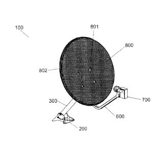
Status: Granted
Bibliographic Data
(51) International Patent Classification (IPC):
  • H01Q 15/16 (2006.01)
(72) Inventors :
  • ABREU, JOAO DO ESPIRITO SANTO (Brazil)
  • ABREU, JOAO ALEXANDRE DE (Brazil)
(73) Owners :
  • ABREU, JOAO DO ESPIRITO SANTO (Brazil)
  • ABREU, JOAO ALEXANDRE DE (Brazil)
(71) Applicants :
  • ABREU, JOAO DO ESPIRITO SANTO (Brazil)
  • ABREU, JOAO ALEXANDRE DE (Brazil)
(74) Agent: BERESKIN & PARR LLP/S.E.N.C.R.L.,S.R.L.
(74) Associate agent:
(45) Issued: 2021-06-08
(86) PCT Filing Date: 2015-05-29
(87) Open to Public Inspection: 2015-12-10
Examination requested: 2019-03-29
Availability of licence: N/A
(25) Language of filing: English

Patent Cooperation Treaty (PCT): Yes
(86) PCT Filing Number: PCT/BR2015/000082
(87) International Publication Number: WO2015/184518
(85) National Entry: 2016-11-02

(30) Application Priority Data:
Application No. Country/Territory Date
BR202014013528 1 Brazil 2014-06-04

Abstracts

English Abstract

The present utility model relates to a parabolic antenna (100) having a base (200), a mounting pole (300), a head unit (400), a rear structure (500), a support pole (600), a low-noise converter (700) and a reflector (800), the reflector (800) being made in a single piece from laminated expanded screen that has a perfectly parabolic, self-structured shape without any bearing frame, is fastened to the rear structure (500) of the parabolic antenna (100) by means of a fastening unit (801) and has a reinforcement edge (802) facing away from the concavity of the reflector (800) and rolled on one or two levels in the peripheric region of the reflector (800), wherein the reflector can have one or more perforated or smooth sections (803) with arbitrary vertical and/or horizontal orientations, extending over the fastening unit (801).


French Abstract

Le présent modèle d'utilité concerne une antenne parabolique (100) comprenant une base (200), un socle (300), une partie tête (400), une structure arrière (500), une tige de support (600), un convertisseur à faible bruit (700) et un réflecteur (800), ledit réflecteur (800) étant fabriqué en une seule pièce en toile expansée stratifiée et de forme parfaitement parabolique, auto-structuré sans armature de support, fixé à la structure arrière (500) d'antenne parabolique (100) par l'intermédiaire d'une unité de fixation (801) et doté d'un bord de renforcement (802) tourné dans le sens opposé à la concavité du réflecteur (800) et réalisé de manière enroulée ou en un ou deux niveaux sur la zone périphérique du réflecteur (800), pouvant posséder un ou plusieurs segments non perforés ou lisses (803), avec des orientations aléatoires verticales et/ou horizontales et qui s'étendent par-dessus l'unité de fixation (801).

Claims

Note: Claims are shown in the official language in which they were submitted.

5
Claims
1. Parabolic antenna with self-structured reflector, having a base,
mounting pole, head
unit, rear structure, support pole, low noise converter, and reflector,
characterized in that
said reflector is made in a single piece in laminated expanded screen, that
has a parabolic,
self-structured shape without any bearing frame, fastened to the rear
structure of the
parabolic antenna by means of a fastening unit and having a reinforcement edge
facing
away from the concavity of the reflector, and rolled or in one or two levels
in the peripheral
region of the reflector.
2. The parabolic antenna according to claim 1, characterized in that it
comprises one or
more perforated or smooth sections, in arbitrary vertical and/or horizontal
orientations
extending over the fastening unit.
Date Recue/Date Received 2020-07-31

Description

Note: Descriptions are shown in the official language in which they were submitted.


CA 02947777 2016-11-02
1
PARABOLIC ANTENNA WITH SELF-STRUCTURED REFLECTOR
Field of Application
[001] The present utility model belongs to the field of
telecommunication equipment industry, notably for satellite communication
antennas.
Introduction
[002] The present utility model relates to a constructive disposition
introduced into a telecommunication antenna, especially in the type of
satellite communication antenna used, for example, for the reception of pay
television signals via satellite or DTH (Direct-to-Home), commonly known as
parabolic antenna
[003] The parabolic antenna according to the present utility model is
equipped with a self-structured reflector set in a perfectly parabolic shape,
made from laminated expanded screen, having a lightweight, rigid, and
permeable to the wind construction, optimizing the use of metallic material
and consequently reducing the manufacturing cost.
State of the art
[004] Even so the preferred constructive form for DTH parabolic
antennas is that one including metallic reflectors, usually solid ones,
especially for providing accuracy to the reflective surface at levels smaller
than 0.5 mm RMS (Root-Mean-Square or root mean square error), various
technical solutions that feature the reflective surface built in screen,
especially a metallic screen, are known from the state of the art, as shown,
for example, by the patent document US 4.568.945.
[005] The advantage of using metallic screens instead of solid metal
plates is to obtain a surface that, in addition to being lighter, offers less
wind
resistance and enables the construction of lighter antennas in general. The
disadvantage of using screens is the lack of stiffness of the same and the
consequent demand for structural elements that allow the construction of
minimally stiff reflective surfaces.

CA 02947777 2016-11-02
2
[006] This construction is made, usually, by segmentation of the
reflective surface, as shown, for example, in patent documents US
4.578.682, US 2.997.712, US 3.234.550 and US 4.647.943 in various
segments supported by ribs, struts, stringers, fins, finally, a series of
components that increase the amount of items in an antenna, its mounting
complexity and, almost always, the final mass.
[007] In addition, segmentation of the reflective surface and the lack
of structural stiffness of the metal screens make it impossible to obtain a
parabolic shape as perfect as the ones made from rigid printed screens in
one solid piece, resulting in semi-parabolic or umbrella-shaped antennas.
[008] Said deficiency is evident observing the aforementioned
documents and also documents US 2.471.828, US 4.378.561 and, in
particular, document US 3.397.399.
[009] There is, therefore, room for a constructive disposition
introduced in telecommunications antenna to provide a parabolic antenna
equipped with self-structured reflector set manufactured in one single piece
in laminated expanded screen and perfectly parabolic shape.
Objective of the utility model
[010] The objective of the present utility model is, thus, providing a
parabolic antenna with self-structured reflector according to the features of
claim 1 in the appended set of claims. Variation of shape or detail related to

constituent elements of the model that do not alter the technical-functional
unit and the body unit in the matter of claim 1, are defined in the dependent
claim in the appended set of claims.
Brief description of the drawings
[011] For a better understanding and visualization of the object of the
present utility model, the same will now be described with reference to the
attached drawings, representing the functional improvement obtained
wherein, schematically:

CA 02947777 2016-11-02
3
[012] Figure 1: is an anterolateral perspective view of a parabolic
antenna with self-structured reflector according to
the utility model;
[013] Figure 2: is a posterolateral perspective view of a parabolic
antenna with self-structured reflector according to
the utility model;
[014] Figure 3: is a side perspective view of a parabolic antenna
with self-structured reflector according to the utility
model;
[015] Figure 4: is an anterolateral perspective view of a shape
variation of the parabolic antenna with self-
structured reflector according to the utility model;
and
[016] Figure 5: is an anterolateral perspective view of a shape
variation of the parabolic antenna with self-
structured reflector according to the utility model;
[017] Figure 6: is an anterolateral perspective view of a shape
variation of the parabolic antenna with self-
structured reflector according to the utility model;
and
[018] Figure 7: is an anterolateral perspective view of a shape
variation of the parabolic antenna with self-
structured reflector according to the utility model;
[019] Figure 8: shows detail "A" of Figure 6, in a rolled condition;
and
[020] Figure 9: shows detail "A" of Figure 6, in one or two levels.
Detailed description of the utility model
[021] Figures 1, 2 and 3 show a parabolic antenna (100) with a base
(200), a mounting pole (300), head unit (400), rear structure (500), support

CA 02947777 2016-11-02
4
pole (600) and low noise converter (700), usual in the state of the art and to

the skilled in the art, not demanding, therefore, greater details.
[022] A parabolic antenna (100) according to the present utility model
with a reflector (800) being made in a single piece, fastened to the rear
structure (500) of the parabolic antenna (100) by means of a fastening unit
(801), and having a reinforcement edge (802) facing away from the
concavity of the reflector (800), and made in a rolled form (figure 8) or in
one
or two levels (figure 9) in the peripheral region of the reflector (800).
[023] Thus, a reflector (800) equipped with a reflective surface with a
perfect parabolic profile is obtained, and so, with superior performance to
the models with conventional state of the art screens described above.
[024] In addition, the parabolic antenna (100) having the reflector
(800) according to the present utility model does not require structural ribs
and bearing frames, thus being lighter and having lower manufacturing cost
in comparison to known screen antennas.
[025] For the allocation of a mechanical reinforcement to the
parabolic antenna (100) and, thus also the construction of parabolic
antennas (100) of larger diameters, the reflector (800) can be equipped with
one or more non-perforated or smooth sections (803), in random directions,
for example, vertical and/or horizontal, which preferably pass over the
fastening unit (801), as can be inferred from figures 4, 5, 6 and 7.
Conclusion
[026] As can be inferred from the description above, the constructive
disposition according to the present utility model surpasses the state of the
art, being an object of practical use, perfectly susceptible of industrial
application, comprising a new disposition, involving inventive step and
resulting in functional improvement in its use, providing a parabolic antenna
(100) with a self-structured reflector (800) made in a single piece in
laminated expanded screen, and having a perfectly parabolic shape.

Representative Drawing
A single figure which represents the drawing illustrating the invention.
Administrative Status

For a clearer understanding of the status of the application/patent presented on this page, the site Disclaimer , as well as the definitions for Patent , Administrative Status , Maintenance Fee  and Payment History  should be consulted.

Administrative Status

Title Date
Forecasted Issue Date 2021-06-08
(86) PCT Filing Date 2015-05-29
(87) PCT Publication Date 2015-12-10
(85) National Entry 2016-11-02
Examination Requested 2019-03-29
(45) Issued 2021-06-08

Abandonment History

There is no abandonment history.

Maintenance Fee

Last Payment of $210.51 was received on 2023-05-08


 Upcoming maintenance fee amounts

Description Date Amount
Next Payment if small entity fee 2024-05-29 $100.00
Next Payment if standard fee 2024-05-29 $277.00

Note : If the full payment has not been received on or before the date indicated, a further fee may be required which may be one of the following

  • the reinstatement fee;
  • the late payment fee; or
  • additional fee to reverse deemed expiry.

Patent fees are adjusted on the 1st of January every year. The amounts above are the current amounts if received by December 31 of the current year.
Please refer to the CIPO Patent Fees web page to see all current fee amounts.

Payment History

Fee Type Anniversary Year Due Date Amount Paid Paid Date
Application Fee $400.00 2016-11-01
Maintenance Fee - Application - New Act 2 2017-05-29 $100.00 2016-11-01
Maintenance Fee - Application - New Act 3 2018-05-29 $100.00 2018-04-11
Request for Examination $800.00 2019-03-29
Maintenance Fee - Application - New Act 4 2019-05-29 $100.00 2019-03-29
Maintenance Fee - Application - New Act 5 2020-05-29 $200.00 2020-05-19
Final Fee 2021-05-19 $306.00 2021-04-15
Maintenance Fee - Application - New Act 6 2021-05-31 $204.00 2021-05-21
Maintenance Fee - Patent - New Act 7 2022-05-30 $203.59 2022-05-05
Maintenance Fee - Patent - New Act 8 2023-05-29 $210.51 2023-05-08
Owners on Record

Note: Records showing the ownership history in alphabetical order.

Current Owners on Record
ABREU, JOAO DO ESPIRITO SANTO
ABREU, JOAO ALEXANDRE DE
Past Owners on Record
None
Past Owners that do not appear in the "Owners on Record" listing will appear in other documentation within the application.
Documents

To view selected files, please enter reCAPTCHA code :


To view images, click a link in the Document Description column. To download the documents, select one or more checkboxes in the first column and then click the "Download Selected in PDF format (Zip Archive)" or the "Download Selected as Single PDF" button.

List of published and non-published patent-specific documents on the CPD .

If you have any difficulty accessing content, you can call the Client Service Centre at 1-866-997-1936 or send them an e-mail at CIPO Client Service Centre.


Document
Description 
Date
(yyyy-mm-dd) 
Number of pages   Size of Image (KB) 
Examiner Requisition 2020-04-16 3 143
Maintenance Fee Payment 2020-05-19 1 33
Amendment 2020-07-31 7 221
Claims 2020-07-31 1 19
Electronic Grant Certificate 2021-06-08 1 2,527
Final Fee 2021-04-15 5 129
Representative Drawing 2021-05-14 1 25
Cover Page 2021-05-14 1 61
Abstract 2016-11-02 1 22
Claims 2016-11-02 1 22
Drawings 2016-11-02 4 154
Description 2016-11-02 4 170
Representative Drawing 2016-11-02 1 34
Cover Page 2016-11-30 1 66
Request for Examination 2019-03-29 1 52
PCT Correspondence 2017-02-08 9 483
International Search Report 2016-11-02 2 165
Amendment - Abstract 2016-11-02 2 99
National Entry Request 2016-11-02 5 128
Correspondence 2016-11-09 1 32
Correspondence 2017-02-24 1 51