Note: Descriptions are shown in the official language in which they were submitted.
REPLACEMENT HEART VALVES AND THEIR METHODS OF USE AND MANUFACTURE
[001] This application claims the benefit of and priority to US Provisional
Patent
Application Serial No. 61/991,354, filed May 9, 2014.
FIELD
[002] The subject matter described herein relates generally to improved
replacement valves,
such as for the aortic and mitral valves of the heart.
BACKGROUND
[003] The human heart has a number of valves for maintaining the flow of
blood through
the body in the proper direction. The major valves of the heart are the
atrioventricular (AV)
valves, including the bicuspid (mitral) and the tricuspid valves, and the
semilunar valves,
including the aortic and the pulmonary valves. When healthy, each of these
valves operates in a
similar manner. The valve translates between an open state (that permits the
flow of blood) and
a closed state (that prevents the flow of blood) in response to pressure
differentials that arise on
opposite sides of the valve.
[004] A patient's health can be placed at serious risk if any of these
valves begin to
malfunction. Although the malfunction can be due to a variety of reasons, it
typically results in
either a blood flow restricting stenosis or a regurgitation, where blood is
permitted to flow in the
wrong direction. If the deficiency is severe, then the heart valve may require
replacement.
[005] Substantial effort has been invested in the development of
replacement heart valves,
most notably replacement aortic and mitral valves. Replacement valves can be
implanted
percutaneously by way of a transfemorally or transapically introduced
catheter, or can be
implanted directly through open heart surgery. The replacement valves
typically include an
- 1 -
Date Recue/Date Received 2021-05-31
arrangement of valve leaflets that are fabricated from porcine tissue or an
artificial material such
as a polymer. These leaflets are maintained in position by a stent or support
structure.
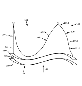
[006] FIG. lA is a perspective view depicting a prior art prosthetic heart
valve 8 of U.S.
Patent No. 7,682,389 ("Beith"). This valve 8 can be implanted directly and
includes a stent 10
and three leaflets 30. When implanted, blood is permitted to flow from the
upstream (blood
inlet) end 14 towards the downstream (blood outlet) end 12, but is prevented
from flowing in the
reverse direction by the presence of leaflets 30. Leaflets 30 have free edges
34 located on the
downstream end 12. Each leaflet 30 also has a fixed edge (or interface) 32
joined with scalloped
edge portions 16a, 16b, and 16c, respectively, of stent 10. A cross-sectional
plane "I" is shown
that bisects the leaflet 30 joined with fixed edge 16a (located at front
right). Cross-sectional
plane "I" is parallel to the direction of the flow of blood and thus is
vertical in FIG. 1A.
[007] FIG. 1B is a side view of a right-side portion of valve 8 after
rotation such that plane
"I" is aligned with the page. From the reader's perspective FIG. 1B is viewed
along a normal to
plane "I." From this view, the entirety of fixed edge 32 of leaflet 30 (which
is aligned with edge
16a) lies in a flat plane and is straight with no curvature.
[008] FIG. 1C is a side view of a right-side portion of another prior art
valve 8 after rotation
such that plane "I" is aligned with the page (like the case with FIG. 1B).
Here, fixed edge 32 is
fully concave from the perspective exterior to valve 8. In the prior art, this
fully concave shape
was believed to assist in the movement of the leaflet from the open position
to the closed
position where the leaflet is pushed or draped into the valve interior, as
adequate coaptation in
the closed state is essential for the proper functioning of the valve.
[009] However, the flat and fully concave shapes of the prior art designs
described with
respect to FIGs. 1A-1C can lead to a valve with compromised hydrodynamic
efficiency due to
- 2 -
Date Recue/Date Received 2021-05-31
the fact that the local leaflet length at various heights of the valve is not
long enough. This can
lead to inadequate valve opening. It can also (or alternatively) lead to local
bulging and
tightness. The flat or fully concave shapes can both result in localized
stress concentrations that,
in combination with the aforementioned bulging and tightness, can result in
reduced durability
and premature failure.
[010] U.S. Patent No. 6,613,086 ("Moe") describes other variations in the
shape of the
support structure (or valve body) for a directly implantable valve. Moe
describes "an attachment
curve" that is defined as the position where the leaflets are coupled along
the inner wall of the
support structure. Moe seeks to increase the durability of each leaflet
coupled to the support
structure by moving the leaflet's point of maximum loaded stress along the
attachment curve and
away from the location of any stress risers. Moe does this by adjusting the
radius of the support
structure at different heights along the support structure's axis of flow (see
numeral 26 of FIG. 1)
and at different radial positions within each cross-sectional plane taken
perpendicular to and at
different heights along the support structure's axis of flow. As a result,
Moe's support structures
have substantially non-circular or non-cylindrical inner walls along the
attachment curve. These
support structures can have significantly asymmetric shapes with substantial
surface variations,
as evidenced by the bulges 58 and 60 described with respect to FIG. 11 of Moe.
Moe's support
structures are neither cylindrical nor substantially cylindrical as those
terms are used herein.
[011] While trying to reduce the localized stress, Moe's approaches lead to
local
lengthening of the leaflet at that height in the valve. This local lengthening
will lead to an
increase in the resistance of the leaflet to open and could compromise the
full opening of the
valve, leading to local bulging in the leaflet surface. This, in turn, will
reduce the hydrodynamic
efficiency of the valve and potentially reduce the durability of the valve
leaflet.
- 3 -
Date Recue/Date Received 2021-05-31
[012] For these and other reasons, needs exist for improved prosthetic
valves.
SUMMARY
[013] Example embodiments of improved prosthetic heart valves and their
methods of use
and manufacture are provided herein. In some of these example embodiments, the
prosthetic
heart valve can include: a support structure having a central axis oriented in
the direction of
blood flow through an interior of the support structure; and a plurality of
artificial leaflets, each
leaflet having a base along the support structure and a free edge allowed to
move independent of
the support structure. Each leaflet can also have a central axis extending
between the base and
the free edge. The support structure can be substantially cylindrical where
the base of each
leaflet meets the support structure. The artificial leaflets can be adapted to
move between a first
position, for preventing the flow of blood through an interior of the support
structure, and a
second position, for allowing the flow of blood through the interior of the
support structure. For
each leaflet, a profile of the base of the leaflet can be at least partially
convex when viewed from
an exterior of the support structure along a normal to a plane formed by the
central axis of the
support structure and the central axis of the leaflet. Additional embodiments
are also disclosed.
[013a] In accordance with one aspect, the present application provides a
prosthetic heart
valve, comprising a support structure having a central axis oriented in the
direction of blood flow
through an interior of the support structure; and a plurality of artificial
leaflets, each leaflet
having a base along the support structure and a free edge allowed to move
independent of the
support structure, each leaflet also having a central axis extending between
the base and the free
edge, wherein the artificial leaflets are adapted to move between a first
position, for preventing
the flow of blood through an interior of the support structure, and a second
position, for allowing
- 4 -
Date Recue/Date Received 2021-05-31
the flow of blood through the interior of the support structure, wherein the
support structure is
substantially cylindrical where the base of each leaflet meets the support
structure, and wherein,
when a first one of the plurality of leaflets is viewed from an exterior of
the support structure
along a normal to a plane formed by the central axis of the support structure
and the central axis
of the first leaflet, a profile of the base of the first leaflet is at least
partially convex.
[013b1 In accordance with another aspect, the present application provides
a prosthetic heart
valve, comprising a support structure having an interior; and a plurality of
artificial leaflets, each
leaflet having a base along the support structure and a free edge allowed to
move independent of
the support structure, wherein the artificial leaflets are adapted to move
between a first position,
for preventing the flow of blood through the interior of the support
structure, and a second
position, for allowing the flow of blood in a direction through the interior
of the support
structure, wherein the support structure is substantially cylindrical where
the base of each leaflet
meets the support structure, and wherein, for each leaflet, a profile of the
base of the leaflet is at
least partially convex when viewed from an exterior of the support structure
along a normal to a
center plane of the leaflet oriented parallel to the direction of blood flow
through the interior of
the support structure.
[013c1 In yet another aspect, the present application provides a method of
manufacturing a
prosthetic heart valve, comprising molding or casting a plurality of synthetic
leaflets onto a
support structure, wherein, for each synthetic leaflet, the base of the
synthetic leaflet is in
continuous contact with an annular base portion of the support structure to
form an intersection
having a partially concave segment between the annular base portion and an
apex of the support
structure.
- 5 -
Date Recue/Date Received 2021-05-31
[013d] In a further aspect, the present application provides a prosthetic
heart valve,
comprising a support structure having a central axis oriented in the direction
of blood flow
through an interior of the support structure, an annular base portion and
three extensions oriented
in the direction of blood flow and each terminating in an apex; three
artificial leaflets with a
base along the support structure and a free edge allowed to move independent
of the support
structure, each artificial leaflet movable between a first position, for
preventing the flow of blood
through an interior of the support structure, and a second position, for
allowing the flow of blood
through the interior of the support structure; wherein the base each leaflet
is in continuous
contact with the support structure to form an intersection having a segment
between the annular
base portion, and each apex, wherein a convex portion of the segment tapers at
an increasing rate
between the annular base portion and the apex.
[013e] In yet another aspect, the present application provides a prosthetic
heart valve,
comprising a support structure having a base portion, a first end, a second
end, a central axis
extending therebetween, and three extensions oriented in a direction of blood
flow and each
having an apex, wherein the support structure is substantially cylindrical;
and three artificial
leaflets, each leaflet having a movable part with a leaflet base along the
base portion of the
support structure and a free edge allowed to move independent of the base
portion of the support
structure, wherein the leaflet base is a casting boundary between the movable
part and the
support structure, and wherein an intersection of the leaflet base and the
support structure forms
a continuous curved interface having convex portions on opposite sides of each
apex wherein the
convex portions contain a midway point along the continuous curved interface
between the base
portion and the apex; and wherein the movable part of each leaflet is movable
between a closed
position and an open position.
- 6 -
Date Recue/Date Received 2021-05-31
[013f] In a further aspect, the present application provides a prosthetic
heart valve,
comprising a support structure having a central axis oriented in the direction
of blood flow
through an interior of the support structure, an annular base portion, and 3
extensions oriented in
the direction of blood flow and each terminating in an apex; three artificial
leaflets, a base along
the support structure and a free edge allowed to move independent of the
support structure, each
movable between a first position, for preventing the flow of blood through an
interior of the
support structure, and a second position, for allowing the flow of blood
through the interior of
the support structure [where free edges of each of the three artificial
leaflets form a substantially
concentric annular configuration with the substantially cylindrical support
structure wherein the
base forms an intersection along a continuous contact with the support
structure, wherein the
intersection is comprised of six convex portions each spaced away from, and on
opposite sides
of, each apex.
[13g] In still another aspect, the present application provides a
prosthetic heart valve,
comprising a substantially cylindrical support structure having a central axis
oriented in the
direction of blood flow through an interior of the support structure, an
annular base portion and
three extensions oriented in the direction of blood flow and each terminating
in an apex; three
artificial leaflets, each leaflet having a movable part with a base along the
support structure and a
free edge allowed to move independent of the support structure, the movable
part of each leaflet
also having a central axis extending between the base and the free edge,
wherein the movable
part of each leaflet is each movable between a first position, for preventing
the flow of blood
through an interior of the support structure, and a second position, for
maximizing the flow of
blood through the interior of the support structure, wherein in the open
position the free edges of
- 7 -
Date Recue/Date Received 2021-05-31
the leaflets form an annular configuration concentric with the annular extent
of the support
structure except at each apex.
[014] Other systems, methods, features and advantages of the subject matter
described
herein will be or will become apparent to one with skill in the art upon
examination of the
following figures and detailed description. It is intended that all such
additional systems,
methods, features and advantages be included within this description, be
within the scope of the
subject matter described herein, and be protected by the accompanying claims.
In no way should
the features of the example embodiments be construed as limiting the appended
claims, absent
express recitation of those features in the claims.
BRIEF DESCRIPTION OF FIGURES
[015] The details of the subject matter set forth herein, both as to its
structure and operation,
may be apparent by study of the accompanying figures, in which like reference
numerals refer to
like parts. The components in the figures are not necessarily to scale,
emphasis instead being
placed upon illustrating the principles of the subject matter. Moreover, all
illustrations are
intended to convey concepts, where relative sizes, shapes and other detailed
attributes may be
illustrated schematically rather than literally or precisely.
[016] FIG. 1A is a perspective view depicting a prior art prosthetic heart
valve.
[017] FIG. 1B is a side view of a right-hand portion of the prior art valve
after rotation such
that plane "I" is aligned with the page.
[018] FIG. 1C is a side view of a right-hand portion of another prior art
valve after rotation
such that plane "I" is aligned with the page.
[019] FIGs. 2A-B are perspective views of the front half of an example
embodiment of a
support structure for a prosthetic heart valve.
- 8 -
Date Recue/Date Received 2021-05-31
[020] FIGs. 2C-D are top down views of an example embodiment of prosthetic
valve
leaflets in open and closed states, respectively.
[021] FIG. 2E is an illustrative view depicting a portion of an example
embodiment of a
prosthetic valve in a laid flat state.
[022] FIGs. 2F-H are perspective views of an example embodiment of a
prosthetic heart
valve.
[023] FIGs. 2I-J are perspective views of an example embodiment of a
prosthetic heart
valve in line drawing and surface shaded forms, respectively.
[024] FIG. 2K is a perspective view of an example embodiment of a
prosthetic heart valve.
[025] FIG. 3A is a color top down view comparing the positions of two sets
of leaflets in
their open states, where the support structure is not shown.
[026] FIG. 3B is a color perspective view comparing the positions of two
sets of leaflets in
their open states within the front half of a prosthetic heart valve where the
support structure is
not shown.
[027] FIG. 3C is a color top down view comparing the positions of two sets
of leaflets in
their closed states, where the support structure is not shown.
[028] FIG. 3D is a color perspective view comparing the positions of two
sets of leaflets in
their closed states within the front half of a prosthetic heart valve where
the support structure is
not shown.
[029] FIG. 3E is a color perspective view depicting an example embodiment
of leaflets in
their open state with the stress levels experienced at various positions
across the surface of the
leaflets, where the support structure is not shown.
- 9 -
Date Recue/Date Received 2021-05-31
[030] FIG. 3F is a color perspective view depicting conventional leaflets
in their open state
with the stress levels experienced at various positions across the surface of
the leaflets, where the
support structure is not shown.
[031] FIG. 3G is a color perspective view depicting an example embodiment
of leaflets in
their closed state with the stress levels experienced at various positions
across the surface of the
leaflets, where the support structure is not shown.
[032] FIG. 3H is a color perspective view depicting conventional leaflets
in their closed
state with the stress levels experienced at various positions across the
surface of the leaflets,
where the support structure is not shown.
[033] FIG. 31 is a color top down view depicting an example embodiment of
leaflets in their
closed state with the stress levels experienced at various positions across
the surface of the
leaflets, where the support structure is not shown.
[034] FIG. 3J is a color top down view depicting conventional leaflets in
their closed state
with the stress levels experienced at various positions across the surface of
the leaflets, where the
support structure is not shown.
[035] FIG. 3K is a color frontal view depicting an example embodiment of a
leaflet mapped
with the simulated relative degree of vertical strain energy release.
[036] FIG. 3L is a color frontal view depicting a conventional leaflet
mapped with the
simulated relative degree of vertical strain energy release.
[037] FIG. 3M is a color frontal view depicting an example embodiment of a
leaflet
mapped with the simulated relative degree of lateral strain energy release.
[038] FIG. 3N is a color frontal view depicting a conventional leaflet
mapped with the
simulated relative degree of lateral strain energy release.
- 10 -
Date Recue/Date Received 2021-05-31
[039] FIGs. 4A-B are perspective views depicting the front half of
additional example
embodiments of a support structure.
[040] FIG. 5A is a flowchart depicting an example embodiment of a method of
manufacturing a prosthetic heart valve.
[041] FIG. 5B is a photograph depicting an example embodiment of a mandrel
for use in a
dip casting manufacturing method.
[042] FIG. 5C is a photograph depicting an example embodiment of a base
frame for use in
a dip casting manufacturing method.
DETAILED DESCRIPTION
[043] Before the present subject matter is described in detail, it is to be
understood that this
disclosure is not limited to the particular embodiments described, as such
may, of course, vary.
It is also to be understood that the terminology used herein is for the
purpose of describing
particular embodiments only and is not intended to be limiting.
[044] Example embodiments of systems, devices, kits, and methods are
provided herein that
relate to valve replacement in a patient. These embodiments will be described
primarily with
respect to replacement of the natural aortic heart valve with a prosthetic
heart valve having three
artificial (i.e., man-made) leaflets. However, the scope of the present
disclosure is not limited to
such, and can likewise be applied to prosthetics for replacement of other
valves of the heart (e.g.,
mitral) where those prosthetics have two or more leaflets. These prosthetics
may also be used to
replace valves in other locations in the patient's body outside of the heart.
[045] The example embodiments of the prosthetic valves disclosed herein
are, in many
cases, designed in a manner different from those manners taught by the prior
art. FIGs. 2A-B are
perspective front views and FIGs. 2C-D are top down views of one such example
embodiment of
- 11 -
Date Recue/Date Received 2021-05-31
a prosthetic valve 100. Referring to FIG. 2A, a support structure 102 meets a
plurality of valve
leaflets 110-1, 110-2, and 110-3. Each of leaflets 110 can be discrete from
the others (as shown
here) or can be portions of one unitary (monolithic) leaflet body.
[046] Support structure 102, which can also be referred to as a stent, is
configured to allow
blood to flow in direction 101 and has an upstream end 103 and a downstream
end 104. Support
structure 102 also includes an annular base portion 105 that can have a planar
or flat upstream
terminus (not shown) or that can have a curved or scalloped upstream terminus
as shown here.
Support structure 102 also includes three extensions 106 that project from
annular base portion
105 towards downstream end 104.
[047] Extensions 106 include curved interfaces 107, which are located
directly on an edge
in this embodiment. Here, each curved interface 107 is the location where
support structure 102
meets the operable base 111 of a leaflet 110. In many embodiments curved
interfaces 107 and
the leaflet bases 111 will coincide.
[048] In the embodiment depicted in FIG. 2A, support structure 102 is in
the form of a base
frame. The leaflets can be integrally formed on this base frame 102, such as
through a casting
(e.g., dip casting) or molding process. A dip casting process that is suitable
for formation of the
leaflets is described with respect to FIGs. 5A-C. In an example of a dip
casting process, the base
frame 102 is placed on a mandrel and dipped in a polymer, which results in the
formation of
leaflets integrated with a polymeric coating over the base frame. Here, curved
interfaces 107
refer to the boundary between support structure 102 and each of the integrated
leaflets (i.e., base
111 of each leaflet). Depending on the particular implementation, curved
interfaces 107 can
coincide with the downstream edge of the base frame itself or the downstream
edge of the
coating over the base frame.
- 12 -
Date Recue/Date Received 2021-05-31
[049] In some embodiments, leaflets 110 (whether they be tissue or
artificial) can be
physically joined to support structure 102 through a coupling process such as
sewing. FIG. 2E is
an illustration of an example embodiment of a portion of valve 100 in a laid
flat state. Here,
leaflet 110-1 has been coupled to support structure 102 by a seam 201 created
by sewing a suture
202 through leaflet 110-1 and support structure 102. The physical base edge
204 of leaflet 110
can be located upstream from seam 201 (as shown), folded back into a location
downstream of
seam 201, or otherwise. In these embodiments, both curved interface 107-1 and
base 111-1 refer
to the transition between the secured portion of leaflet 110-1 and the
operable portion of leaflet
110-1 that is free to transition or deflect between the open and closed
states, which in the
embodiment of FIG. 2E coincides with the upstream edge of support structure
102.
[050] Referring back to FIG. 2A, annular base portion 105 also includes
flanges 108 and
109 between which a sewing cuff (not shown) can be placed. As an alternative
for all of the
embodiments described herein, only a single flange 108 may be present, or the
flanges 108 and
109 can be omitted altogether. In light of this description, those of ordinary
skill in the art will
readily understand the design and appearance of a sewing cuff and how it can
be coupled with
one or more flanges of support structure 102.
[051] In FIG. 2A, support structure 102 is positioned according to the
perspective depicted
by line 2A-2A of FIG. 2C. Stated differently, cross-sectional plane "I" of
FIG. 2C is parallel to
the page of FIG. 2A such that the viewer views FIG. 2A along a normal "N" to
plane "I". Plane
"I" can also be described as extending through a central axis of valve 100
oriented in the
direction of blood flow (indicated by the solid circle at the tip of the
normal "N" arrow in FIG.
2C) and a central axis of the respective leaflet extending between base 111
and free edge 112.
- 13 -
Date Recue/Date Received 2021-05-31
An example of the central axis is where plane "I" intersects leaflet 110-1 in
FIGs. 2C-D. There,
plane I is a center plane or mid-plane to leaflet 110-1.
[052] FIG. 2B depicts the embodiment of FIG. 2A in an annotated form to
allow
comparison with the flat downstream edges 70-1 and 70-2 that would be present
if support
structure 102 was shaped according to the prior art approach of FIGs. 1A-B.
Here, interfaces
107-1 and 107-2 can be seen to bulge in a pronounced fashion from flat edges
70-1 and 70-2.
Note that edge 70-2 is referred to as flat because it would appear flat if
support structure 102
were rotated to place edge 70-2 in the position of edge 70-1 in FIG. 2B. The
bulges of interface
107-1 and 107-2 would be even more pronounced if compared to the prior art
concave edge
approach of FIG. 1C. Although interface 107-3 and 70-3 are not shown, the same
relationships
would present for those as well.
[053] FIG. 2C depicts leaflets 103 in their open positions with support
structure 102
omitted. However, were support structure 102 to be shown, apex Al of extension
106-1 and
apex A2 of extension 106-2 (both shown in FIG. 2A) would be positioned as
noted in FIG. 2C.
[054] Leaflets 103 each have a free edge 112 that moves independent of
support structure
102. FIG. 2D depicts leaflets 110 after movement to their closed positions. In
the closed
position, in many embodiments the majority of free edges 112 will be in
contact with each other.
In some embodiments, the entirety of free edges 112 will be in contact with
each other.
[055] As seen in FIG. 2A, interface 107-1 is partially convex and concave
from the
perspective exterior to valve 100. Interface 107-1 coincides with base 111-1
of leaflet 130-1 (see
FIGs. 2I-K). The convex portion 120 is midway along interface 107-1. Convex
portion 120 is
convex in two dimensions, e.g., like a portion of the border of a two-
dimensional ellipse from the
perspective of outside the ellipse.
- 14 -
Date Recue/Date Received 2021-05-31
[0561 Concave portions 121-1 and 121-2 can be present on both sides of the
convex middle
portion 120. As seen in FIG. 2A, concave portion 121-1 has a significantly
lower degree of
curvature than convex middle portion 120. The combination of a convex portion
with one or
more concave portions gives interface 107-1 an undulating appearance when
viewed from this
perspective. This appearance can also be referred to as S-shaped or multi-
curved if there is at
least one concave portion and at least one convex portion (e.g., two concave
portions and two
convex portions qualifies as S-shaped), and those portions can vary in height
and degree of
curvature. In some embodiments, interface 107-1 can be convex along its entire
height (or
length). In other embodiments, interface 107-1 can include a convex portion
with a flat (or
linear) portion on one or both sides. In still other embodiments, interface
107-1 can include a
convex portion in combination with any number of flat portions and concave
portions.
[0571 FIG. 2F is a perspective front view of another example embodiment of
a support
structure 102 for a prosthetic valve 100. In this embodiment, the degree of
curvature present in
convex portion 120 and concave portions 121-1 and 121-2 is relatively less
than in the
embodiment described with respect to FIG. 2A. FIG. 2G is a perspective front
view of the
embodiment of FIG. 2F annotated to allow comparison of interfaces 107-1 and
107-2 with prior
art edges 70-1 and 70-2 (described with respect to FIG. 2B).
[0581 In FIGs. 2F-G, only the front half of support structure 102 is shown
(i.e., forward of
plane "I"), with the back half and valve leaflets 110 omitted for ease of
illustration. The entire
support structure 102 is depicted in the perspective view of FIG. 2H. FIGs. 2I-
2J are a line
drawing perspective view and surface shaded perspective view, respectively, of
the embodiment
of FIG. 2F with leaflets 110 included. FIG. 2K is a line drawing perspective
view of the
embodiment of FIG. 2F taken from a different perspective than that of FIG. 21.
- 15 -
Date Recue/Date Received 2021-05-31
[059] In addition to being described as "convex," certain convex portions
of interface 107-1
can be described as tapering at an increasing rate as the distance increases
from upstream end
103. Characterized in yet another manner, the convex curve may be regarded as
"concave
down" with respect to a straight line reference similar to edge 70-1 described
with respect to
FIG. 2B. The convexity may change in direction to "concave up" (i.e., change
in mathematical
sign considering a second derivative of interface 107-1) and/or may change in
magnitude (i.e., in
terms of degree of curvature) along the length of interface 107-1.
[060] For all of the embodiments described herein, any of the
aforementioned shapes can
likewise be present on interfaces 107-2 and 107-3 when those interfaces 107-2
and 107-3 are
viewed from the same perspective as interface 107-1 in FIG. 2A. Preferably,
each of interfaces
107-1, 107-2 and 107-3 has the same shape to maximize the synchronous motion
of leaflets 110,
as significantly asynchronous motion can negatively impact the durability of
valve 100.
However, each interface 107 can vary in shape with respect to the others
provided that the
durability of valve 100 remains acceptable.
[061] While support structure 102 can take various shapes, in all
embodiments, support
structure 102 can be substantially cylindrical or cylindrical. As those of
ordinary skill in the art
understand, being "cylindrical" does not require support structure 102 to be
in the form of a full
geometric cylinder (e.g., vertical walls oriented at a right angle to a
circular cross-section), but
rather requires support structure 102 to lie along a part of a hypothetical
geometric cylinder (with
only minor deviation). For example, the entire inner lumen surface (the
surface directly adjacent
the flow of blood) of support structure 102 as depicted in FIG. 2D is
cylindrical as that term is
used herein. Similarly, those of ordinary skill in the art understand that a
support structure 102
that is "substantially cylindrical" is permitted greater deviation from a
mathematical cylinder
- 16 -
Date Recue/Date Received 2021-05-31
than simply "a cylindrical support structure" and would readily recognize
those support
structures that qualify as being substantially cylindrical.
[062] While the entirety of support structure 102 can be cylindrical or
substantially
cylindrical, it is also the case that only part of support structure 102 can
be cylindrical or
substantially cylindrical, with the remaining part of support structure 102
being non-cylindrical.
For instance, in the embodiment described with respect to FIG. 2D, although
the entire inner
lumen surface of support structure 102 is cylindrical, the opposite outer
surface has flanges 108
and 109 that are not cylindrical.
[063] In other embodiments, only the portion of support structure 102 along
curved
interfaces 107 (e.g., along base 111 of leaflets 110) may be cylindrical or
substantially
cylindrical. Such a configuration distinguishes over the subject matter of
U.S. Patent No.
6,613,086 ("Moe") described herein.
[064] When support structure 102 is formed from a base frame coated in
polymer, then in
some embodiments, only the base frame (either the entirety or a portion
thereof) can be
cylindrical or substantially cylindrical, while the outer surface of the
polymer coating is not
cylindrical or not substantially cylindrical. For example, in some embodiments
the inner lumen
surface of a base frame is cylindrical and the outer surface of the polymer
coating (along the
inner lumen of the base frame) is substantially cylindrical (or even non-
cylindrical) due to
variations in the coating thickness.
[065] In the embodiments of FIGs. 2A-B and 2F-K, valve 100 is sized to fit
a 23 millimeter
(mm) aortic tissue annulus, although this embodiment can be sized at other
standard dimensions
as well, such as 17mm, 18mm, 19 mm, 20 mm, 21 mm, 22 mm, 24 mm, 25 mm, 26 mm,
27 mm,
28 mm, and 29 mm, as well as dimensions that lie in between. These dimensions
are commonly
- 17 -
Date Recue/Date Received 2021-05-31
referred to as the inner diameter or "ID" of valve 100, which is the lateral
dimension of the valve
at a position commensurate with leaflets 110. The valve may have an even
larger lateral
dimension elsewhere, such as the location of the sewing cuff.
[066] FIG. 4A depicts another embodiment of valve 100 (in a view similar to
that of FIG.
2A). In this embodiment, valve 100 is sized for a 19 mm tissue annulus.
Interface 107-1
includes a convex portion 401 with a smaller flat or concave portion 402 near
apex Al of
extension 106-1. Interface 107-1 of valve 100 can again be seen to bulge in a
pronounced
convex fashion from the overlaid flat edge 70-1. Interface 107-2 and 107-3
(not shown) have
similar shapes.
[067] FIG. 4B depicts another embodiment of valve 100 (again in a view
similar to that of
FIG. 2A). In this embodiment, valve 100 is sized for a 27 mm tissue annulus.
Interface 107-1 is
S-shaped with a first slightly convex portion 403 adjacent apex Al, a concave
portion 404
immediately upstream (below), and a second slightly convex portion 405
upstream from (below)
concave portion 404. Overlaid flat edge 70-1 is again present to further
illustrate the differences
with interface 107-1 of this embodiment of valve 100. Interface 107-2 and 107-
3 (not shown)
have similar shapes.
[068] The embodiments of valve 100 described herein are suitable for
implantation in the
body of a patient using any number of medical procedures. Preferably, these
embodiments of
valve 100 are for direct implantation to the aortic annulus using open heart
surgery. Such
embodiments of valve 100 are not radially collapsible for insertion into an
intravascular delivery
device (e.g., a catheter) or a transapical delivery device. However, in other
embodiments, valve
100 can be configured with a radially collapsible support structure 102 that
allows the lateral
- 18 -
Date Recue/Date Received 2021-05-31
dimension of valve 100 to be reduced by a degree sufficient to permit the
insertion into an
appropriately sized intravascular or transapical delivery device.
[069] All of the embodiments of valve 100 described herein can also be
provided to a
medical professional (or retained by a medical professional) as part of a kit
(or a set) of
prosthetic valves being sized for various tissue annulus dimensions. The sizes
can include any
combination of two or more of the following: 17mm, 18mm, 19mm, 20mm, 21mm,
22mm,
23mm, 24mm, 25mm, 26mm, 27mm, 28mm, and 29mm. In one embodiment, the kit
includes at
least one valve 100 configured with an at least partially convex interface 107
as described herein,
along with one or more valves having different configurations. In another
embodiment, for each
labeled size, the kit includes at least one of the embodiments of a valve 100
described herein. In
still another embodiment, the kit includes a 19 mm valve 100 in the form of
the embodiment
described with respect to FIG. 4A, a 23 mm valve 100 in the form of the
embodiment described
with respect to FIG. 2F, and a 27mm valve 100 in the form of the embodiment
described with
respect to FIG. 4B.
[070] Support structure 102 can be fabricated from any desired material,
such as polymers
(e.g., polyether ether ketones (PEEK), polyurethanes, etc.), metals (e.g.,
nitinol, stainless steel,
etc.), and others. Leaflets 110 are fabricated from an artificial polymeric
material, including any
biostable polyurethanes and polyurethane compositions (e.g., polysiloxane-
containing
polyurethanes, etc.) known in the art. Examples of polyurethane containing
leaflets are
described in U.S. Patent No. 6,984,700, U.S. Patent No. 7,262,260, U.S. Patent
No. 7,365,134,
and Yilgor et al., "Silicone containing copolymers: Synthesis, properties and
applications," Prog.
Polym. Sci. (2013). Materials that approach ideal isotropic non-creeping
characteristics are
particularly suitable for use in many embodiments. While many materials can be
used, it is
- 19 -
Date Recue/Date Received 2021-05-31
preferable that the selected material have the appropriate modulus of
elasticity to allow leaflets
110 to readily and repeatedly transition between the open and closed states
without succumbing
to fatigue or stress related failure. In many example embodiments, the modulus
of elasticity for
leaflets 110 is in the range of 10-45 MegaPascals (MPa). In certain other
example embodiments,
the modulus of elasticity for leaflets 110 is in the range of 20-30 MPa.
[071] Valves 100 designed in accordance with the embodiments described
herein exhibited
superior performance over previous valves in a number of respects. For
example, FIGs. 3A-N
are a series of simulation outputs that compare the performance of leaflets of
an embodiment of a
23mm valve 100 having leaflets 110 (similar to that described with respect to
FIGs. 2F-K) as
compared to a valve having a flat edge 70 with leaflets 72 similar to the
prior art approach
described with respect to FIGs. 1A-B as well as FIGs. 2B, 2G, and 4A-B. Such
comparisons
demonstrate the improved performance of the at least partially convex edge
embodiments over
the prior art flat edge approach (as well as the prior art concave edge
approach described with
respect to FIG. 1C).
[072] FIG. 3A is a top down view of leaflets 110 (blue) in their open
position as compared
to leaflets 72 (red) each having a base that would be attached to flat edge
70. It is seen here that
the free edges of leaflets 110 approach the wall of support structure 102 (not
shown) much more
closely than the free edges of leaflets 72 and thus provide significantly less
resistance to blood
flow through the interior of valve 100. This is shown further in FIG. 3B,
which is a view of open
leaflets 110 in an orientation corresponding to that of FIG. 2F but without
showing support
structure 102. The visible surfaces are those that are closest to the viewer.
Almost the entirety
of leaflets 110 are closer to the viewer than leaflets 72, resulting in a
larger interior space through
which blood can flow.
- 20 -
Date Recue/Date Received 2021-05-31
[073] FIG. 3C is a top down view of leaflets 110 (blue) in their closed
position as compared
to leaflets 72 (red). Visible surfaces indicate those that are closest to the
viewer looking into
valve 100 from the downstream end. Leaflets 110 extend further into the
interior of valve 100
than leaflets 72, and achieve a higher degree of coaptation and thus a better
seal against backflow
and regurgitation, particularly in the center where all three of leaflets 110
meet. Leaflets 110
also eliminate the buckled or dimpled portion that is present in each of
leaflets 72 and seen as the
circular spots. Leaflets 110 of FIG. 3C is shown from a different perspective
in FIG. 3D.
[074] FIG. 3E is a perspective of leaflets 110 in the open position showing
the stress levels
experienced at various positions across the surface of leaflets 110. In FIGs.
3E-N, increasing
relative stress is indicated by color in the following order: dark blue
(lowest relative stress), light
blue, green, yellow, orange, and red (highest relative stress). The maximum
principal stress
experienced by leaflets 110 was calculated to be 2.64 (MPa). This is compared
to leaflets 72 of
FIG. 3F, which is shown on the same scale as FIG. 3E and indicates that
leaflets 72 generally
experience higher stress, particularly across the center region of leaflets 72
and along the mid-
region of the bases. The maximum principal stress experienced by leaflets 72
was calculated to
be 2.75 MPa.
[075] FIG. 3G is a perspective of leaflets 110 in the closed position
showing the stress
levels experienced at various positions across the surface of leaflets 110.
The maximum
principal stress experienced by leaflets 110 in this position was calculated
to be 2.75 MPa. FIG.
3H, which is shown on the same scale as FIG. 3G, indicates that leaflets 72
experience higher
stress in pockets positioned on both sides of each leaflet 72 near the
junction of the free edge and
base. The maximum principal stress for leaflet 72 was 3.005 MPa, which is
again higher than for
leaflets 110.
- 21 -
Date Recue/Date Received 2021-05-31
[076] FIG. 31 is a top down view of the simulation of leaflets 110 in FIG.
3G and FIG. 3J is
a top down view of the simulation of leaflets 72 in FIG. 3H. This comparison
shows the higher
degree of coaptation achieved by leaflets 110, particularly at the center of
valve 100 and where
adjacent free edges meet in proximity to the support structure (not shown).
[077] FIG. 3K is a front view of leaflet 110 mapped with the simulated
relative degree of
vertical strain energy release. FIG. 3L is a front view of leaflet 72 showing
the simulated
relative degree of vertical strain energy release according to the same scale
as FIG. 3K. FIG. 3M
is a front view of leaflet 110 mapped with the simulated relative degree of
lateral strain energy
release. FIG. 3N is a front view of leaflet 72 showing the simulated relative
degree of lateral
strain energy release according to the same scale as FIG. 3M.
[078] Strain energy release is determined by an integral across the entire
cycle of motion of
the leaflet, i.e., movement between the open and closed positions and back.
Vertical strain
energy release is a measurement of how much energy is present at each position
on the leaflet to
drive the growth of a defect in the vertical direction, i.e., between bottom
and top as shown in
FIGs. 3K-L. Lateral strain energy release is a measurement of how much energy
is present at
each position on the leaflet to drive the growth of a defect in the lateral
direction, i.e., between
left and right sides as shown in FIGs. 3M-N.
[079] As can be seen in FIGs. 3K-L, leaflet 110 experiences significantly
reduced vertical
strain energy release, which was calculated to be 110.331 joules per mm
squared (J/mm2), as
compared to 132.151 J/mm2 for leaflet 72. The most significantly reduced
regions are shown in
the lower center portion of leaflet 110 and in the upper corners of leaflet
110 where the free edge
and base come together.
- 22 -
Date Recue/Date Received 2021-05-31
[080] With respect to the lateral strain energy releases depicted in FIGs.
3M-N, leaflet 110
again experiences significant reductions as compared to leaflet 72. In this
example, the lateral
strain energy release for leaflet 110 was determined to be 61.315 Jimm2 and
the lateral strain
energy release for leaflet 72 was determined to be 71.097 Jimm2.
[081] These significant reductions in strain energy release allows for the
use of a wider
range of materials in leaflets 110, such as those having lower cut-growth
thresholds that may
exhibit superior overall performance as compared to those having higher cut-
growth thresholds.
Alternatively, the same materials with high cut growth thresholds may be
employed but with
prospects for longer lifetime in use.
[082] Leaflets 110 are coupled to support structure 102 in a number of
ways, such as
adhesives, molding, casting, sewing, fasteners, and others known to those of
ordinary skill in the
art. FIG. 5A is a flow diagram depicting an example embodiment of a method 500
of
manufacturing certain embodiments of prosthetic heart valve 100 using a dip
casting process. At
502, a base frame is fabricated from a rigid material such as a polyether
ether ketone (PEEK), a
polyetherimide (PEI) such as ULTEMTm, and the like. This can be done by
machining or
injection molding. At 504, the base frame is placed on a dipping mandrel that
has the shape of
the interior surface of the support structure and leaflets. An example
embodiment of a base
frame 501 is depicted in the photograph of FIG. 5B. An example embodiment of a
dipping
mandrel 503, without the base frame, is depicted in the photograph of FIG. 5C.
Mandrel 503 can
be inserted into a polymeric solution with forming equipment that envelops the
base frame and
casts the leaflets in the desired form.
[083] At 506, the base frame and mandrel is dipped in a polymeric solution
under both high
temperature and humidity and then withdrawn. Although the methods disclosed
herein are not
- 23 -
Date Recue/Date Received 2021-05-31
limited to such, in some example embodiments, the relative humidity (RH) can
be in the range of
20-80% and the temperature can be in the range of 20-50 degrees C. Step 506
can result in a
manifestation of support structure 102 and leaflets 111 together in an
integrally formed but
unfinished state.
[084] Dipping step 506 can be performed only once to arrive at the fully
formed (but
unfinished) valve, or can be performed multiple times (e.g., two times, three
times, or as many
times as desired). In one embodiment, the base frame is fabricated from a
first material (e.g.,
PEEK) different than the polymeric material from which the leaflets are
fabricated. In that case
it may be desirable to form the leaflets to the base frame only after the base
frame has been pre-
coated by the leaflet polymer to provide for greater cohesion. The base frame
can be pre-coated
by first dipping the base frame in the leaflet polymer having a first
viscosity. This can be done
with or without the mandrel. If done with the mandrel, the resulting leaflets
can be removed.
The pre-coated base frame can then be placed on the mandrel and dipped again,
this time in the
leaflet polymer with the same or a relatively higher viscosity. This second
dipping can result in
the formation of the full leaflet bodies integrally formed with the support
structure. Use of a low
viscosity followed by a higher viscosity can allow for formation of a thin pre-
coating that does
not significantly distort the shape of the underlying base frame followed by
formation of the
leaflets having the desired thickness.
[085] At 508, support structure 102 and leaflets 111 can be trimmed and
otherwise finished
to achieve accurate and precise edges and surface smoothness. This can occur,
for example,
through laser cutting, ultrasonic trimming, water knife, a mechanical clam
shell cutter, and the
like. Finally, at 510, a sewing cuff can be coupled with support structure 102
and the final
device can be packaged in the desired sterile container.
- 24 -
Date Recue/Date Received 2021-05-31
[086] Those of ordinary skill in the art will readily recognize, in light
of this description, the
many variations of suitable dip casting procedures, pressures, and
temperatures that are not
stated here yet are suitable to fabricate the prosthetic heart valves
described herein. Likewise,
those of ordinary skill in the art will also recognize, in light of this
description, the alternatives to
dip casting that can be used to fabricate the prosthetic heart valves
described herein.
[087] As already mentioned, the embodiments of prosthetic heart valve 100
described
herein can be directly implanted into the heart of the patient. In one such
example procedure, the
appropriate size replacement valve can be determined and then an open heart
access procedure is
performed by a surgeon to gain access to the malfunctioning valve of the heart
that will be
replaced. The surgeon can then position the selected prosthetic heart valve
100 in position over
the malfunctioning valve and attach valve 100 to the surrounding tissue. The
attachment can
occur, for instance, by fastening the sewing cuff to the tissue with one or
more sutures. Prior to
attachment, if the surgeon determines that the selected valve size is not
optimal, then a different
valve having a different size can be selected and placed in position within
the heart. In some
other embodiments, the malfunctioning valve can be removed prior to
positioning valve 100 in
the intended location. Once valve 100 is attached, the open heart cavity is
closed and the
procedure is ended.
[088] As used herein and in the appended claims, the singular forms "a",
"an", and "the"
include plural referents unless the context clearly dictates otherwise.
[089] It should be noted that all features, elements, components,
functions, and steps
described with respect to any embodiment provided herein are intended to be
freely combinable
and substitutable with those from any other embodiment. If a certain feature,
element,
component, function, or step is described with respect to only one embodiment,
then it should be
- 25 -
Date Recue/Date Received 2021-05-31
understood that that feature, element, component, function, or step can be
used with every other
embodiment described herein unless explicitly stated otherwise. This paragraph
therefore serves
as antecedent basis and written support for the introduction of claims, at any
time, that combine
features, elements, components, functions, and steps from different
embodiments, or that
substitute features, elements, components, functions, and steps from one
embodiment with those
of another, even if the following description does not explicitly state, in a
particular instance, that
such combinations or substitutions are possible. It is explicitly acknowledged
that express
recitation of every possible combination and substitution is overly
burdensome, especially given
that the permissibility of each and every such combination and substitution
will be readily
recognized by those of ordinary skill in the art.
[090] While the embodiments are susceptible to various modifications and
alternative
forms, specific examples thereof have been shown in the drawings and are
herein described in
detail. It should be understood, however, that these embodiments are not to be
limited to the
particular form disclosed, but to the contrary, these embodiments are to cover
all modifications,
equivalents, and alternatives falling within the spirit of the disclosure.
Furthermore, any
features, functions, steps, or elements of the embodiments may be recited in
or added to the
claims, as well as negative limitations that define the inventive scope of the
claims by features,
functions, steps, or elements that are not within that scope.
[091] Other systems, devices, methods, features and advantages of the
subject matter
described herein will be or will become apparent to one with skill in the art
upon examination of
the following figures and detailed description. It is intended that all such
additional systems,
devices, methods, features and advantages be included within this description,
be within the
scope of the subject matter described herein, and be protected by the
accompanying claims. In
- 26 -
Date Recue/Date Received 2021-05-31
no way should the features of the example embodiments be construed as limiting
the appended
claims, absent express recitation of those features in the claims.
- 27 -
Date Recue/Date Received 2021-05-31