Note: Descriptions are shown in the official language in which they were submitted.
CA 02947919 2016-11-03
WO 2014/191565 PCT/EP2014/061288
Cable Anchorage with Bedding Material
The present invention relates to the field of cable anchorages such
as may be used, for example, for anchoring stay cables. In particular, but not
exclusively, the invention relates to the anchoring of cables comprising
multiple
strands which are held under tension and which are subject to static and/or
dynamic deflection.
Background of the invention
Stay cables may be used for supporting bridge decks, for example,
and may typically be held in tension between an upper anchorage, secured to a
tower of the bridge, and a lower anchorage, secured to the bridge deck. A
cable
may comprise dozens or scores of strands, with each strand comprising multiple
(eg 7) steel wires. Each strand is typically retained individually in each
anchorage
by tapered conical wedges, seated in a conical hole in an anchor block.
Tensioning
of the strands can be performed from either end, for example using hydraulic
jacks. When in use, cables may be subjected to lateral, axial and/or torsional
forces
due to vibration or other movement of the bridge deck (which may arise due to
wind, or to the passing of heavy traffic, for example). As a result of the
above
effects, the cables may experience lateral, axial and/or torsional oscillatory
motion.
This oscillatory motion may be in the cable as a whole (ie the strands of the
cable
moving together), or it may be in individual strands, or both. Other cables,
such as
pre-stressing cables, may also be subject to static and/or dynamic deflection
at or
near the end anchorages.
Such oscillatory movements in a cable, strand or wire may result in
damages of the individual strands and of the anchorage, due to repeated
impacts
between the strand and strand channel, and due to bending stress notably where
the strands are anchored . This friction between strand and strand channel
can,
over time, cause fretting, work-hardening or other damage to the cable and/or
to
the anchorages, thereby significantly reducing the serviceable life of the
cable
and/or anchorage, and greatly increasing the maintenance and monitoring effort
required. Replacing damaged strands is a time-consuming and expensive
CA 02947919 2016-11-03
WO 2014/191565 PCT/EP2014/061288
2
operation and usually entails significant interruption of traffic in the case
of a
bridge. This is particularly so if all of the strands in a cable must be
replaced at
once.
Prior art
To at least partially overcome this problem, a prior art solution
consists in using an individual deviator element at the mouth of the anchorage
where each strand emerges. Such a channel exit with a curved surface is
disclosed
for example in European patent EP1181422, in which the mouth of each
anchorage channel is shaped as a flared opening having a constant radius of
curvature. The deviator element in this patent offers a curved surface,
trumpet
shaped, against which each strand can press when it experiences lateral
deviation,
thereby extending the length of the contact region between the strand and the
anchorage where lateral forces due to bending are transferred between the
strand and the anchorage, and reducing localized damage which might otherwise
occur as a result of persistent localized fretting of the strand against an
abrupt
edge. This solution increases the amount of deviation of the cable which can
be
tolerated at the exit of the anchorage (and hence increase the maximum span of
cable which can be anchored). Such a curved surface reduces the surface of
contact between the strand and the wall of the strand receiving channel at the
anchorage end turned towards the running part of the strand. Nevertheless this
solution cannot accommodate important strand deviations, requires a
supplemental trumpet shaped part or an adaptation of the construction of the
anchorage's exit, which induce supplemental costs. Also due to the enlarged
possible deviation of each strand, the overall dimension of the anchorage is
considerably increased.
The magnitude of the angular deviations which can be tolerated by
the anchorages also imposes significant restrictions on the design of the
structure
which is being supported or tensioned. For example, longer cable spans, with
lighter and more flexible deck structures, result in greater angular
deviations at
the end anchorages. The current trend towards more flexible structures
therefore
means that the anchorages must be able to cope with greater angular deviations
CA 02947919 2016-11-03
WO 2014/191565 PCT/EP2014/061288
3
of the cables. A bridge deck supported centrally by a single planar "fan" of
stay
cables, for example, undergoes significantly greater rotation of the deck, and
hence engenders significantly more angular deviation in the stay cables at the
anchorages than a bridge deck suspended from two lateral planes of stay
cables.
In such prior art existing anchorage, the deviator elements or curved
guide surfaces are sited where the strands exit from the anchorage, on the
assumption that this is where the deflections in the strand cause the most
damage
to the strand. However, as will be discussed later, the combination of the
bending
stresses in the cable and the lateral clamping stresses applied by the wedges,
means that it is the anchoring (clamping) region, not the exit region, which
is
often the most critical location for the fatigue performance of the cable and
the
individual strands.
The length and curvature of the curved surfaces must be selected to
be suitable for the anticipated angle of deflection in the strands. Larger
1 5 deflections require longer curved surfaces. However, the proximity of
the strands
to each other in the anchorage dictates that there is a maximum practicable
length of the curved surfaces, and/or a minimum radius of curvature, thus
limiting
the maximum deflection angle which can be specified for the anchorage.
Moreover, in such prior art existing anchorages, the required
minimum length of the deviator elements or curved guide surfaces results in a
minimum axial length of the anchorages which is longer than the minimum
structural depth required to support the anchored cable forces. They therefore
imply additional costs to the total cost of the structure manufacturing and/or
repairing.
It is an object of the present invention to overcome one or more of
the disadvantages of prior art anchorages.
In particular, an aim of the invention is to provide another means
for reducing the damages to the cable strands and to the anchorage caused by
CA 02947919 2016-11-03
WO 2014/191565 PCT/EP2014/061288
4
static deviations and possible oscillatory movements of the cable, in
particular at
the exit of the anchorage.
Another aim of the invention is to provide an anchorage which
requires smaller dimensions and distances between strands than the prior art
anchorages.
Those aims are achieved by a method of anchoring a strand subject
to static and dynamic deflection in a cable anchorage, the cable anchorage
comprising an anchor block, a strand channel through the anchor block,
extending
between an anchoring end and an exit end, and a strand-anchoring conical wedge
at said anchoring end of the anchor block, for transferring an axial tension
load in
the strand to the anchor block, the length of the strand channel being less
than 10
times the smallest diameter of the strand channel, the method comprising:
a filling step, in which a space surrounding the strand in the strand-channel
is at
least partially filled with a flexural and/or elastic bedding material having
a
durometer at 23 C in the range 10 to 70 Shore, so as to form a bedding cushion
extending substantially around the strand in the strand-channel and axially
along
a bedding region of the axial length of the strand-channel.
Those aims are also achieved by a cable anchorage comprising: an
anchor block, a strand channel through the anchor block, extending between an
anchoring end and an exit end, for accommodating a strand subject to static
deflection in the strand channel, the length of the strand channel being less
than
10 times the smallest diameter of the strand channel, and a strand-anchoring
conical wedge at said anchoring end of the anchor block, for transferring an
axial
tension load in the strand to the anchor block, in which a bedding cushion
extends
substantially around the strand in the strand-channel and axially along a
bedding
region of the axial length of the strand-channel, the bedding cushion
comprising a
flexural and/or elastic bedding material having a durometer at 23 C in the
range
10 to 70 Shore.
The presence of an adapted elastic or flexural bedding cushion
between each strand and the inner wall of each corresponding individual
channel
CA 02947919 2016-11-03
WO 2014/191565 PCT/EP2014/061288
of the anchor block ensures, in addition to protecting the strand against
corrosion,
that any bending stresses which are still present in the strand where the
strand
enters the anchor block are quickly and efficiently transferred to the anchor
block
by means of "elastic bedding", as will be described in more detail below. Thus
it is
5 possible virtually to eliminate bending stresses in the strand at the
point where
the strand enters the wedge, and thereby protect the strand from damage under
the influence of static or dynamic deviations.
Such an elastic bedding material forming a bedding cushion in the
strand-channel, between the strand and the anchor block, further damps the
vibrations of the strand in the strand channel by absorbing at least partially
the
vibrational energy of the portion of the strand located in the strand-channel.
Therefore the solution induces also a reduction of the oscillatory movements
of
the strand.
Another advantage of this anchorage is that it can be made shorter
than those of the prior art, and accommodate greater deflection angles of the
cable or strand(s).
The use of such a bedding cushion can be implemented for strands
which are already in services, either during an adaptation procedure of prior
art
existing anchorages (total or partial replacement of the existing less or not
performant bedding material, such as grease). Also, the use of a bedding
cushion
according to the present invention can be combined with deviator elements or
curved guide surfaces of prior art existing anchorages.
The invention also envisages a construction comprising one or more
cable anchorages as previously mentioned.
Reference is made throughout this application to the example of
anchorages for stay cables comprising steel strands. However, it should be
understood that the invention may be applied to anchorages for any type of
cables, eg stay cable, hangers, external tendons etc, comprising rope, wire or
strands etc which are subject to deviation at or near the anchorage. Such
cables
CA 02947919 2016-11-03
WO 2014/191565 PCT/EP2014/061288
6
etc are often made of steel, but the invention presented here is not limited
to
steel cables, and may be applied to cables made of other materials, such as
carbon
or other structural fibres. The terms "cable" and "strand" should thus be
interpreted as covering any kind of flexible longitudinal tension element
which
may be subject to angular deviation. The invention described here is thus
susceptible of application in all types of structure in which such cables are
required
to be anchored.
Note also that the terms "deviation" and "deflection" are used
interchangeably in this application.
The term "axial" is used to refer to a direction parallel to the
longitudinal axis of the anchorage and/or to the cable. Similarly, references
to
"length" in this application refer to dimensions measured along the axial
direction.
The invention will now be described in more detail with reference to
the attached drawings, in which:
Figure 1 shows in schematic form a cross-sectional view along a
longitudinal plane through an anchorage and a multi-strand cable.
Figure 2a illustrates schematically a single strand held in an anchor
block of an anchorage according to the invention.
Figure 2b illustrates schematically the compressive stiffness of the
bedding cushion in the anchorage of figure 2a.
Figure 2c shows, in greatly exaggerated, schematic form, a
transverse deflection of the strand of figure 2a.
Figure 2d shows schematically the bending stresses in the strand of
figure 2a when subjected to a deflection such as that shown in figure 2c.
CA 02947919 2016-11-03
WO 2014/191565 PCT/EP2014/061288
7
Figure 3 shows, in schematic, cross-section al view, an anchorage
according to a first embodiment of the invention.
Figure 4 shows an enlarged section (A) of the anchorage of figure 3.
Figure 5 shows, in schematic, cross-sectional view, an anchorage
according to a second embodiment of the invention.
Figure 6 shows an enlarged section (B) of the anchorage of figure 5.
The figures are provided for illustrative purposes only, as an aid to
understanding certain principles underlying the invention, and they should not
be
taken as limiting the scope of protection sought. Where the same reference
numerals are used in different figures, these are intended to refer to the
same or
equivalent features. However, the use of different numerals is not necessarily
intended to indicate any particular difference between the features to which
they
refer.
As shown in figure 1, a cable 8 may comprise individual strands 50
which are anchored individually in an anchor block 11 of an anchorage. The
anchor block typically comprises a solid block of a metal such as steel, and
is
designed to hold the cable 8 in tension against a part of the structure, 4,
being
prestressed or supported. The strands 50 must be separated from each other in
the
anchor block 11 in order to allow space for the anchoring means (eg conical
wedges 12 at the anchoring end 1 of the anchor block 11), and the separated
strands 50 exit from the anchor block 11 at the exit end 3 of the anchor block
11
and may be gathered together by a collar 13, also referred to as a deviator,
so that
the strands are bundled closely together with along the main running portion
of
the cable 8, thereby minimising wind-exposure (in the case of a bridge stay
cable).
In the illustrated example, each strand is anchored by conical wedge sections
12
which fit around the strand, gripping it in compression in corresponding
conical
bores when the strand is under tension.
The region 56 of the anchorage in which the strand is gripped, or anchored, is
referred to in the application as the gripping or anchoring region, and the
CA 02947919 2016-11-03
WO 2014/191565 PCT/EP2014/061288
8
gripping or anchoring can be realized by conical wedges 12, as mentioned, or
by
button heads, compression fittings or any other suitable method. It is in this
gripping region that the strand is particularly vulnerable to damage when the
cable is subject to deflection, because of the combination of axial stress,
bending
stress and transverse clamping stress. Each strand 50 is therefore
individually
contained in one dedicated strand-channel 6.
Figure 1 also shows, greatly exaggerated, how the cable 8, and
consequently the individual wires or strands 50, may be subject to a lateral
deviation while under tension and anchored in anchor block 11. The principal
longitudinal axis 7 of the cable 8 may undergo an instantaneous angle of
deflection 13 at or near the exit of the anchorage of as much as 45mrad or
more
from the longitudinal axis 9 of the anchorage, for example, while the
corresponding maximum deviation a of an individual strand 50 may be as much as
75mrad from the longitudinal axis 9 of the corresponding strand-channel, for
example, depending on the strand's position in the cable 8.
The strand deviation typically has a horizontal component and a
vertical component, for example as a result of resonance in the cable or
external
forces such as a wind force, or as a result of a twisting in a part of the
structure.
As discussed earlier, prior art anchorages have focused on the design
of the exit region of the anchorage, where the strands exit into free air.
The assumption was that this was where potential damage and
failure was most likely to occur as a result of combined axial and bending
stresses
in the strands. However, the applicant has determined that, particularly in
compact anchorages, failure is in fact more likely to occur at the anchoring
region
56 itself, in the region where the strand is gripped. The strand is more
vulnerable
to failure where it is gripped by anchor wedges, for example, because of the
significant lateral compression forces in the strand. There is typically also
some
deformation of the surface of the strand at the anchoring region 56, causing
notch effects, due for example to the gripping profile, such as ribbing, on
the
CA 02947919 2016-11-03
WO 2014/191565 PCT/EP2014/061288
9
inner surface of the wedges. Other types of anchoring may be accompanied by
other sources of vulnerability to failure.
In order to stop bending stresses from reaching the gripping region
(anchoring region), the invention now proposes to use a flexural and/or
elastic
bedding material 51, preferably having a defined stiffness and hardness,
located
in the space between the strand 50 and the inner wall of the channel, as
indicated
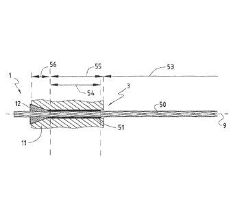
schematically in figure 2a. The bedding material 51 forms a bedding cushion
which extends along a bedding region 54 of the axial length 55 of the strand
channel 6. There is therefore one bedding cushion for each strand 50, said
bedding cushion being made of said bedding material 51. The bedding material
51 may comprise a solid polymeric or elastomeric material or polymeric
elastomer,
notably a visco elastic polymer, such as polyurethane, epoxy-polyurethane,
epoxy
polymer or reticulated epoxy resin, for example, and serves to transfer the
bending stresses to the surrounding, substantially rigid, anchorage structure,
using
an effect known as "elastic bedding". The concept of elastic bedding was
originally developed as a numerical analysis method for modelling flexural
behaviour of structural members supported on soil or other types of ground
material, in order that the flexibility of the ground could be taken into
account
when designing structures in or on the ground. Similar mathematical
calculations
can be carried out to determine the elastic bedding properties (for example
the
compressive stiffness) which are necessary in the bedding material 51 to
ensure
that the lateral bending stresses in the strand 50 are absorbed by the
anchorage in
a bedding region 54 which is as short as is practicable. Note that, in the
context of
the present application, the term "elastic bedding" is not limited to bedding
which has a classical linear elasticity, but may also include bedding which
has non-
linear deformation behaviour. The compressive stiffness of the bedding
material
can be predetermined by selecting bedding material having a particular Shore
value (durometer), for example, and by taking into account the dimensions of
the
space occupied by the bedding material between the strand and the
substantially
rigid material of the surrounding anchorage (eg the steel of anchor block 11),
at
least over the region 54 of the channel (referred to as the bedding region)
over
which the elastic bedding is required to be effective. The free-running or
main
part of the strand 50 is indicated in the figures by reference 53.
CA 02947919 2016-11-03
WO 2014/191565 PCT/EP2014/061288
Figure 2b illustrates the compressive stiffness of elastic bedding (also
referred to as the amount of lateral support), indicated as a function k(x),
which is
offered by the presence of the bedding material 51 to resist the lateral
bending
stresses which arise as a result of a deflection of the free strand by an
angle a,
5 where x represents a distance along a longitudinal axis 9 parallel to the
channels
of the anchorage. As shown on Figure 2b, the bedding material 51 acts like
springs
placed in series along the bedding region 54 between the strand 50 and the
strand-channel 6, and forming a bedding cushion acting like a flexible support
to
limit stress and like a damper for dynamic load.
10 Figure 2c illustrates, greatly exaggerated in the transverse
direction,
the curvature of the strand 50 of figure 2a when it is deflected from its
longitudinal axis 9 by an angle a. The strand 50 bends as it exits from the
mouth
region 3 of the anchor block 11. Existing solutions aim to control the bending
stress in the anchorage by acting at the exit of the anchorage by providing
either
a bell-mouth or a flexible guiding. By contrast, it may be a feature of an
anchorage of the invention to control the bending stress by acting along most
of
the bedding region by providing a non-rigid bedding cushion along the length
of
the bedding region. This provides a more efficient reduction of bending stress
in
the strand, and results in improved control of bedding stress, while reducing
the
distance between the wedges and the exit of the anchorage. Whereas prior art
anchorages were focused on absorbing the bending stress at the channel exit,
and
were therefore designed to mitigate a pivot effect in the strand, for example
by
offering a curved transition surface at the exit to the anchorage, the method
and
anchorage of the present invention focus rather on reducing the bending
effects
in the strand at the gripping region 56, and thus offers an alternative
solution: the
bending is countered within the strand channel by means of the compressive
stiffness of the bedding cushion 51 in the bedding region 54 of the anchor
block
11. By implementing the countermeasures (bedding) against the bending stresses
in the anchor block 11 itself, the overall length of the anchorage can be
greatly
reduced. Furthermore, because elastic bedding is a highly effective
countermeasure for absorbing bending stresses, the method and anchorage of the
invention can be used in situations where the angle of deviation of the
strand/cable is significantly greater than has been possible with prior art
CA 02947919 2016-11-03
WO 2014/191565 PCT/EP2014/061288
11
anchorages of similar length. The inventive anchorage may be used, for
example,
in situations where the deviation angle is as much as 60mrad (static) +/-
15mrad
dynamic, or even more. This capacity for accommodating a much greater
deviation
angle also means that the method and anchorage of the invention can be used
for
anchoring cables which support significantly longer spans than was hitherto
practicable in the prior art.
Figure 2d shows the ben ding stresses in the strand 50 of figure 2a
when it is subjected to a deflection of angle a as shown in figure 2c. The
peak
value 22 of the bending stress occurs somewhere near the exit 3 of the anchor
channel. However, as can also be seen from figure 2d, the elastic bedding
effect
provided by the bedding cushion 51 over the bedding region 54 ensures that the
bending stresses in the strand 50 are reduced, in this example almost
linearly, to a
very small value 23, approaching zero, at the anchoring end of the bedding
region
54.
In prior art anchorages having converging strand channels and an
elastic wall section at the channel exit, such as the anchorage described in
W02012079625, the bending stress due to deflection in the strand does not
diminish as evenly, or as quickly, or to such a low value, as can be achieved
with an
anchorage according to the present invention.
In an anchorage which uses a curved/flared deviator element at the
mouth of the strand channel, such as the anchorages described in EP1227200 and
EP1181422, for example, the bending stress in the strand is still significant
at the
point where the strand enters the gripping region 56. Such anchorages must
thus
be made significantly longer in order for the deviator element to adequately
control the bending stresses at the gripping region 56.
We now turn to examples of how the bedding cushion 51 of the
invention may be provided. The bedding material can be introduced into the
space around the strand inside the channel by injection, for example. Thus, a
liquid polyurethane compound can be injected through or between the anchor
wedges 12, for example, so that it substantially fills the space between the
strand
CA 02947919 2016-11-03
WO 2014/191565 PCT/EP2014/061288
12
50 and the channel wall over the entire length 55, or at least a majority of
the
length, of the channel in the anchor block 11. The type of polyurethane can be
selected so that it flows easily when being injected, and the injection
process can
be further assisted by means of a suction (vacuum) opening, or at least a
vent,
through which the air displaced by the injected liquid can escape or be sucked
out
of the space around the strand 50 in the channel. The liquid is chosen so
that,
once injected, it then hardens to the required durometer, in accordance with
the
elastic bedding calculations.
Alternatively, the bedding material can be introduced in solid form.
This can be achieved by introducing it in the form of particulate or fibrous
material, for example, such as a powder or beads or fibres. If required in
order to
achieve the required elastic and/or flexural properties, a further process,
such as
sintering, may then be performed on the particulate material.
The bedding material may take the form of a coating or sleeve,
fitted or applied to the inside surface of the channel and/or to the outer
surface of
the strand 50, and dimensioned such that the coating or sleeve provides the
required elastic bedding function between the strand 50 and the inner wall of
the
channel. Or, if the material of the channel wall or the strand sheath has
suitable
compressive stiffness and/or elastic properties, it may also form at least
part of the
bedding cushion 51. In that situation, the filling step comprises providing
the
bedding material 51 in the form of a coating or sleeve around the strand 50 in
the
bedding region 54 of the stran channel 6.
Alternatively, one or more of the above variants may be combined
to give the desired elastic bedding effect. The bedding cushion 51 formed by
the
bedding material may completely fill the cavity between the strand 50 and the
wall of the strand-channel 6. However, the desired elastic bedding effect can
also
be achieved even if a gap (not shown) separates the bedding cushion 51 from
the
wall of the strand-channel 6 and/or the strand 50.
The bedding material may advantageously also be selected for its
corrosion-protection properties. Liquid polyurethane, which then hardens to a
CA 02947919 2016-11-03
WO 2014/191565 PCT/EP2014/061288
13
predetermined compressive stiffness, and which adheres well to the surfaces of
the space it fills, is an example of such a bedding material which also serves
to
protect the strand from corrosion.
The introduction of the bedding material as a fluid or particulate
material is advantageously carried out once the strands 50 have been
tensioned,
so that the bedding material can fill the space and assume a shape which will
not
then be significantly deformed by any further large movements of the strand.
In
this way, an optimum bedding is achieved between the strand 50 and the
anchorage body.
The above description refers to a generalised description of how the
invention can be implemented to shorten the length of the anchorage while
still
eliminating or substantially reducing the effects of bending stress at the
anchoring
region 56 of the anchorage. It has been shown that, with a seven wire strand,
in
which each wire is 5.25mm diameter, the bending stress at the anchoring region
56 can be limited to less than 50MPa (magnitude) by the use of a bedding
region
54 which is less than 150mm (eg between 90mm and 150mm) long, and using a
bedding material (or a combination of bedding materials) having a compressive
stiffness of between 50 and 250MPa (preferably between 50 and 180 Mpa) and a
durometer value of 10 to 70 Shore. Preferably the durometer value of in the
bedding material 21 is in the range 10 to 30 Shore or even preferably in the
range
15 to 25 Shore. Using the following relation between the hardness and
the Young's modulus for elastomers :
0.09810-id+ 7 , ,s;
E-
-
0 .13¨ 151 ¨4
Where E is the Young's modulus in MPa and S is the ASTM D2240
type A hardness used as durometer, the bedding material 21 used for the
invention has preferably a stiffness defined by its Young's modulus in the
range
0.4 to 5.5 Mpa , and more preferably in the range 0.4 to 1.1 or even
preferably in
the range 0.6 to 0.9 Mpa
CA 02947919 2016-11-03
WO 2014/191565
PCT/EP2014/061288
14
Prior art anchorages were required to be between 10 and 20 times
as long as the diameter of the strand being anchored in order to provide
adequate bending control. The inventive techniques described here, however,
permit an anchorage to have a channel length 55 which is less than ten times
the
diameter of the strand(s) being anchored.
An additional advantage of using an elastic bedding material of
modest durometer, as described earlier, or an elastic bedding material which
is
separated from the strand by a gap, is that such a bedding cushion offers a
low
resistance to longitudinal movements of the strand. This means that, while the
bedding cushion is sufficiently stiff to provide the desired elastic bedding
function,
it still has sufficiently low strength that the strand can be pulled out of
the
channel with relatively little force. For short anchorages, it is even
possible to pull
a strand out by hand. For longer anchorages, a small capacity jack or other
device
may be required to pull the strand through the anchorage.
Two example embodiments will now be described, which relate to
two typical anchorages for a stay cable: a first, referred to as the "passive
end"
anchorage, and generally located at the less accessible end of the cable,
which
simply holds the strands at one end of the cable. The second, referred to as
the
"stressing end" anchorage, and generally located at the more accessible end of
the cable, allows the strands to be pulled through its anchor block, for
example by
hydraulic jacks, until the strands are individually tensioned to the required
tension.
The first embodiment will be described with reference to figures 3
and 4, while the second embodiment is described with reference to the figures
5
and 6.
Figures 3 and 4 depict an example of an anchorage which is suitable
for the "passive end" application mentioned above. It comprises multiple
channels, 6, formed through an anchor block 11 which may for example be a
block
of hard steel or other material suitable for bearing the large longitudinal
tension
forces. Strands 50 are held in place in the channels 6 by means of conical
wedges
CA 02947919 2016-11-03
WO 2014/191565
PCT/EP2014/061288
12. An orifice element 18 is located at the exit region of the anchorage,
where the
strand 50 emerges from the anchorage. The orifice element 18 may be a moulded
plastic part, for example, and is provided with an inner seal 26, for
providing a
water-tight seal between the orifice element 18 and the strand 50, and an
outer
5 seal 27, for providing a water-tight seal between the orifice element 18
and the
surrounding structure. Also, notably for an easier manufacturing, the orifice
element 18 may be a two-piece part, the assembling of these two pieces
defining
a boundary at the location of a recess for accommodating the inner seal 26.
For
instance these two pieces are in plastic and welded before mounting in the
10 anchorage so that said boundary is water tight. As shown on figures 4 to
5,
preferably, the seal 26 is disposed between the outer surface of the strand 50
and
the inner surface of the strand-channel 6 at a first axial position along the
strand-
channel 6, in an annular or cylindrical recessed region of the inner wall of
the
channel 6, for preventing a transition of liquid between the said volume and
an
15 external region of the cable anchorage located towards the main running
portion
8.
In this example of a passive end anchorage, it is advantageous for
the anchorage to be as short as possible, and the bedding material 51 is thus
provided with optimum compressive stiffness and hardness, and is preferably
continuous and fills the entire space between the strand 50 and the
surrounding
anchor block 11.
Part of the strand 50 (heavily shaded) is sheathed, for example with
a polymeric material. The inner seal 26, which is advantageously formed of an
elastomeric material, therefore bears against the outer surface of the sheath.
The inner seal 26 not only prevents water ingress from the outside
(right-hand side in figures 3 and 4) of the anchorage, but can also serve as a
barrier for defining the extent of the bedding material 51 if the bedding
material
51 is injected as a liquid, for example. In this case, the liquid forming the
bedding
material 51 is contained in the channel defined by the strand-channel 6 (outer
wall), the strand (inner wall) and by the inner seal 26 forming therefore a
terminal
plug. The combination of elastic seal 26 and flexural/elastic bedding material
51
CA 02947919 2016-11-03
WO 2014/191565 PCT/EP2014/061288
16
results not only in a highly effective elastic bedding effect, as discussed
above, but
also as a highly-effective corrosion protection.
Thanks to the presence of the bedding material 51, the overall
length of the anchorage shown in figures 3 and 4 can be significantly reduced
while ensuring low bending stresses at the gripping region of the strand.
A second embodiment is shown in figures 5 and 6 which is similar to
that of figures 3 and 4, but with the addition of a transition pipe 15 and
channel
extension tubes 14, with appropriate adaptation of the orifice elements 18 and
the anchor block 11. This example anchorage is longer than that of the first
embodiment (for example longer than 150mm), and is particularly suitable for
use
as an active end anchorage, where it is less crucial to minimise the overall
length
of the anchorage, since a certain minimum length is required in order carry
out
the strand tensioning or pre-stressing operation. The bedding region 54 can
thus
be longer, and the bedding effect can be distributed over a greater distance.
The
bedding cushion 51 may be such that the diminution gradient (see figure 2d) of
the bending stresses over the bedding region 54 may be less steep than for the
first embodiment. There may be. a gap (not shown) between the bedding cushion
51 and the strand 50 or the channel wall, for example, or the bedding material
51
may be less stiff or less hard than the bedding material used in the first
embodiment.
Strands, particularly the strands of stay cables, are stripped of their
polymer sheath in their end regions before the strands are inserted into the
stressing-end anchorage channel 6. This is so that the wedges 12 can grip
directly
on to the bare steel of the strand, instead of the sheath. Enough sheath must
be
stripped such that, once the strand 50 has been pulled through the 10 channel
6
of the anchor block 11 at the stressing end, and fully tensioned, the end of
the
sheath is located somewhere between the anchoring region 56 and the inner seal
26 of the orifice element 18. The stressing end anchorage is thus required to
be
longer than the passive end anchorage, to allow for axial movement of the
strand
during tensioning. In this case, the channel in the anchor block is
effectively
extended by means of the channel extension tubes,14 , which are enclosed in a
CA 02947919 2016-11-03
WO 2014/191565 PCT/EP2014/061288
17
rigid structure such as solid grout, concrete or other hard filling material
5. The
transition tube 15 is rigid enough to bear the transverse loads caused by the
cable
deviation and transferred either by a hard filling material or for example a
back
plate 20 secured substantially rigidly at the exit region 3 of the anchorage.
As with
the passive end anchorage, the space between the strand 50 and the inner wall
of
the (extended) channel is at least partially filled with a bedding material
51,
preferably over a majority of the length of the anchor block11 and with or
without a gap between the bedding material and the strand, or between the
bedding material and the channel wall. The bedding material 51 may
advantageously also extend through the rest of the strand-channel to the inner
seal 26 of the orifice element 18. Since most of the transverse loads caused
by the
cable deviation will be transferred to the transition pipe near the exit
region of
the anchorage, at a larger distance from the anchor block in this case, the
transition pipe 15 must be rigid enough, and secured to the anchor block
strongly
enough, such that the forces are transmitted by the transition pipe 15 to the
anchor block 11. To this end, a threaded joint 16 has been proposed,
preferably
using a rounded thread in order to minimize fracture points, between the
transition pipe 15 and the anchor block 11. An adjustment ring 10 is also
provided
on the outer periphery of the anchor block 11, for fine adjustment of the
axial
position of the anchor block 11 against the structure 4 which cannot be
provided
by the wedges.
Figure 6 shows how the orifice element 18 is arranged with inner 26
and outer 27 seals, for example in a back plate 20 or other element, sealed to
the
transition tube 15 with a seal such as an 0-ring 19. The orifice element 18 is
also
extended to accommodate the tight-fit channel extension tube 14. Bedding
material 51 is introduced into the space between the strand 50 and the inner
wall
of the channel/extension tubes 14, with or without a radial gap. The extension
tubes 14 and/or the strand sheaths themselves may also form part of the
bedding
material 51/ bedding cushion, in order to provide the required stiffness of
the
elastic/flexural bedding material between the strand 50 and the substantially
rigid
surrounding structure (in this case the grout/concrete/filler 5). The orifice
element
18 may also be constructed as an elastic-walled piece, and may thus contribute
to
the elastic bedding near the exit region 3 if required. The strand channel 6
radially
CA 02947919 2016-11-03
WO 2014/191565 PCT/EP2014/061288
18
extends up to the rigid surrounding structure (in this case the
grout/concrete/filler
5) and accomodates the bedding cushion, i.e the bedding material 51, the
orifice
element 18 and also possible channel extension tube 14 :the diameter of strand
channel 6 is therefore possibly not the same along its length.
The examples and embodiments described above have been
illustrated with examples of anchorages which comprise straight strand
channels
6, parallel to the longitudinal axis 9 of the cable 50 and to each other.
However,
the invention may be used in anchorages in which some or all of the channels
are
not straight, and/or not parallel to each other, and/or not parallel to the
longitudinal axis 9 of the cable 50. The elastic bedding cushion 51 described
above
may be used, for example, in an anchorage in which the strand-channels 6 of
the
anchorage are curved and/or converge towards the free-running portion 53 of
the
cable 50.
In the previous text, the cable anchorage was illustrated in a non-
!imitative way in relation with a stay cable which anchorage was performed at
its
free end contained in the second channel end 6 by means of strand-anchoring
device such as conical wedges 12: Therefore, the present invention can also be
applied to another type of anchorage of the stay cables, namely an anchorage
at a
portion of the stay cable remote from its free ends. When using a cable
deviation
saddle, under some circumstances, there is no possible displacement of portion
of
the strand located at the central portion of the saddle, which situation
therefore
corresponds to an anchorage with the saddle forming a strand-anchoring device
equivalent to the conical wedge 12. This situation corresponds to W02011116828
in which a bedding material 51 can be used in replacement of the usual
material
for protecting strands against corrosion of the strands in the saddle body.
According to a possible variant, the filling is carried out such that
the bedding region 54 extends axially along a single, substantially continuous
portion of the axial length of the strand-channel 6. Alternatively, the
filling is
carried out such that the bedding region 54 comprises two or more
discontinuous
portions of the axial length of the strand-channel 6. Also, preferably, the
filling is
carried out such that axial length of the continuous portion of said bedding
CA 02947919 2016-11-03
WO 2014/191565 PCT/EP2014/061288
19
region 54, or the sum of the axial lengths of the discontinuous portions of
said
bedding region 54, is greater than half the axial length of the strand channel
6. In
a preferred variant, the filling is carried out such that the bedding region
54
extends axially along substantially the entire axial length 55 of the strand-
channel
6. Preferably, the filling is carried out such that the bedding cushion at
least
partially fills the radial separation distance between the outer surface of
the
strand 50 in the strand-channel 6 and a substantially rigid wall of the strand-
channel 6, at least in the bedding region 54. In a preferred variant, the
filling is
carried out such that the bedding cushion substantially fills the radial
separation
distance at least over the axial length of the bedding region 54. Preferably,
the
filling step comprises introducing a liquid into the said space, which liquid
then
hardens to form the bedding material 51. Preferably, the liquid has a
Brookfield
dynamic viscosity of less than 25 poises and preferably less 10 than poises.
Also in a preferred embodiment, the strand-anchoring wedge 12
comprises one or more openings, and the filling step comprises introducing the
bedding material 51 into the space through the openings. In a variant, the
predetermined durometer of the bedding material 51 varies along the bedding
region 54. In a variant, the predetermined stiffness of the bedding material
51
varies along the bedding region 54. Preferably, the variation in stiffness is
achieved by a variation in the thickness of the bedding cushion and/or in the
durometer of the bedding material 51 along the axial length of the bedding
region 54.
Preferably, the method also comprising a sealing step, in which a
seal 26 is provided between the outer surface of the strand and the inner
surface
of the strand-channel 6, and at a predetermined axial position along the
strand-
channel 6, in an annular or cylindrical recessed region of the inner wall of
the
channel 6, so as to prevent an axial movement of the bedding material 51, at
least
while the bedding material 51 is being introduced into the strand-channel 6,
beyond the predetermined axial position in the direction of a main running
portion B of the strand. Preferably, the seal 26 is configured to prevent
ingress of
moisture into the strand-channel 6 from a second end 3 of the strand-channel 6
remote from the strand-anchoring conical wedges 12.
CA 02947919 2016-11-03
WO 2014/191565 PCT/EP2014/061288
In a variant, the filling step comprises an evacuation step of at least
partially evacuating the space before and/or while introducing the bedding
material 51. Preferably, the filling step comprises a testing step of testing
the leak-
tightness of the seal 26. Also, preferably, the cable anchorage comprises a
strand-
5 channel extension element 14 for providing an extension of the axial
length, of
the strand-channel 6 outside the anchor block 11 in a direction towards the
main
running portion 8.
In a variant, the cable anchorage comprises a plurality of the strand-
channels 6, and the method comprises performing the filling, evacuating and/or
10 testing steps on one or more of a plurality of strands 50 in one or more
of the
strand-channels 6 individually. In a variant, the method comprises an
installation
step of installing the strand 50 in the strand-channel 6. Preferably, a
removal step,
is performed before the installation step, of removing a previously-installed
strand
from the strand-channel 6. Preferably, the cable anchorage has one or more
15 evacuation orifices for connection to a vacuum line for evacuating the
said
volume.
Preferably, the cable anchorage 1 comprises a transition region 2
extending axially between the anchor block 11 and a strand exit region 3, and
a
strand-channel extension element 14 for providing an extension of the axial
20 length of the strand-channel 6 through the transition region 2. Also,
preferably,
the cable anchorage comprises a plurality of the strand-channels.
Preferably, the length 54 of the bedding region 54 is at least 90mm,
and preferably at least 150mm.
CA 02947919 2016-11-03
WO 2014/191565
PCT/EP2014/061288
21
Reference numbers used on the figures
1 Anchoring end
3 Exit end
4 Part of the structure
Hard filling material
6 Strand-channel
7 Longitudinal axis of the cable
8 Cable
9 Longitudinal axis of the strand-channel
Adjustment ring
11 Anchor block
12 Anchoring device (conical wedges)
13 Collar or deviator
14 Channel extension tubes
Transition pipe
18 Orifice element
19 0-ring
Back plate
22 Peak value
23 Very small value
26 Inner seal
27 Outer seal
50 Strand
51 Bedding material
53 Free-running or main part of the strand
54 Bedding region
55 Axial length of the strand-channel
56 Gripping or anchoring region