Note: Descriptions are shown in the official language in which they were submitted.
CA 02947960 2016-11-03
WO 2015/130886
PCT/US2015/017655
SECURITY TAG WITH A MAGNETIC GATE
FIELD OF THE INVENTION
[0001] This document relates generally to security tags and associated
detachers. More
particularly, this document relates to a security tag and an associated
detacher for used in an
Electronic Article Surveillance ("EAS") system.
BACKGROUND OF THE INVENTION
[0002] A typical EAS system in a retail setting may comprise a monitoring
system and at
least one security tag or label attached to an article to be protected from
unauthorized
removal. The monitoring system establishes a surveillance zone in which the
presence of
security tags and/or labels can be detected. The surveillance zone is usually
established at an
access point for the controlled area (e.g., adjacent to a retail store
entrance and/or exit). If an
article enters the surveillance zone with an active security tag and/or label,
then an alarm may
be triggered to indicate possible unauthorized removal thereof from the
controlled area. In
contrast, if an article is authorized for removal from the controlled area,
then the security tag
and/or label thereof can be deactivated and/or detached therefrom.
Consequently, the article
can be carried through the surveillance zone without being detected by the
monitoring system
and/or without triggering the alarm.
[0003] The security tags may be reusable, and thus include releasable
attachment devices
for affixing the security tags to the articles. Such attachment devices are
further designed to
be releasable by authorized personnel only so that unauthorized removal of the
security tags
from their articles can be avoided. To this end, many attachment devices are
made releasable
only through the use of an associated special hook or detaching mechanism.
[0004] An exemplary security tag employing an attachment device and an
associated
detacher is described in U.S. Patent No. 5,426,419 ("the '419 patent"),
entitled SECURITY
TAG HAVING ARCUATE CHANNEL AND DETACHER APPARATUS FOR SAME and
assigned to the same assignee hereof. The security tag of the '419 patent
includes a tag body
and an attachment element or device in the form of a tack assembly. The tack
assembly is
used to attach the tag body to an article which is to be protected by the
security tag. This is
accomplished by inserting a tack into an opening in the tag body. When the
tack is fully
1
CA 02947960 2016-11-03
WO 2015/130886 PCMJS2015/017655
inserted into the opening, it is releasably secured in the tag body via a
releasable locking
means. Access to the releasable locking means is through an arcuate channel.
With this
configuration, a special arcuate probe is needed to reach and release the
releasable locking
means, and thus detach the security tag from the article.
[0005] Despite the advantages of this security tag architecture, if suffers
from certain
drawbacks. For example, the security tag can be defeated by inserting a
counterfeit hook or
detaching mechanism (e.g., a steel wire) into the arcuate channel so as to
release the locking
means.
SUMMARY OF THE INVENTION
[0006] The present invention concerns implementing systems and methods for
selectively
preventing an unauthorized detachment of a security tag from an article. The
methods
involve: coupling the security tag to the article by locking a tack assembly
to a securement
member disposed within a housing of the security tag; guiding an external tool
into a channel
formed within the security tag for releasing the tack assembly from the
securement member;
and obstructing the external tool's access to the securement member by biasing
a post into a
first position in which the post at least partially extends into the channel.
A magnetic field
can be applied to the security tag so as to transition the post from the first
position to a second
position in which the external tool's access to the securement member is no
longer obstructed
by the post.
[0007] In some scenarios, the post is biased into the first position using
a resilient
member disposed adjacent thereto within the housing of the security tag. The
magnetic field
may cause compression of the resilient member, whereby the post transitions
from the first
position to the second position. Thereafter, the securement member can be
moved by the
external tool so as to release the tack assembly from the securement member.
More
particularly, the securement member can be rotatably moved by the external
tool so as to
release the tack assembly from a clamp of the securement member. Once the tack
assembly
has been released, the external tool is withdrawn from the channel. Next, the
magnetic field
is no longer applied to the resilient member. In effect, the post is caused to
return to the first
position.
2
81801086
[0007a] According to one aspect of the present invention, there is
provided a method
for selectively preventing an unauthorized detachment of a security tag, from
an article,
comprising: coupling the security tag to the article by locking a tack
assembly to a
securement mechanism disposed within a housing of the security tag; guiding an
external
tool into a channel formed within the security tag for releasing the tack
assembly from the
securement mechanism; and obstructing the external tool's access to the
securement
mechanism by biasing a post into a first position in which the post at least
partially extends
into the channel; further comprising applying a magnetic field to the security
tag so as to
transition the post from the first position to a second position in which the
external tool's
access to the securement mechanism is no longer obstructed by the post.
10007b] According to another aspect of the present invention, there is
provided a
security tag, comprising: a housing; a securement mechanism disposed within
the housing
and configured to releasably lock a tack assembly thereto; a channel formed
within the
housing and configured to guide an external tool through the security tag
towards the
securement mechanism; and a post biased into a first position in which the
post at least
partially extends into the channel so as to obstruct the external tool's
access to the
securement mechanism for releasing the tack assembly therefrom; wherein a
magnetic
field applied to the security tag causes the post to transition from the first
position to a
second position in which the external tool's access to the securement
mechanism is no
longer obstructed by the post.
2a
Date Recue/Date Received 2021-07-23
CA 02947960 2016-11-03
WO 2015/130886 PCMJS2015/017655
DESCRIPTION OF THE DRAWINGS
[0008] Embodiments will be described with reference to the following
drawing figures, in
which like numerals represent like items throughout the figures, and in which:
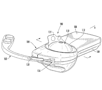
[0009] FIG. 1 is a perspective view of an exemplary security tag and
detachment
mechanism that is useful for understanding the present invention.
[00101 FIG. 2 is a cross sectional side view of the exemplary security
tag shown in FIG. 1
that is useful for understanding the present invention.
[00111 FIG. 3 is a perspective view of a securement mechanism of the
security tag shown
in FIG. 1.
[0012] FIG. 4 is a top perspective view of a bottom portion of the
exemplary security tag
shown in FIG. 1.
[0013] FIGS. 5-6 provide schematic illustrations that are useful for
understanding a gate
structure of the exemplary security tag shown in FIG. 1.
[00141 FIGS. 7-10 provide schematic illustrations that collectively show
operations of the
.. gate structure shown in FIGS. 5-6.
[0015] FIG. 11 is a top perspective view of an exemplary detacher that is
useful for
understanding the present invention.
[0016] FIG. 12 is a schematic illustration that is useful for
understanding how the
detacher operates for detaching the security tag of FIG. 1 from an article.
[0017] FIG. 13 is a flow diagram of an exemplary method for preventing an
unauthorized
detachment of a security tag from an article.
DETAILED DESCRIPTION OF THE INVENTION
[0018] It will be readily understood that the components of the
embodiments as generally
described herein and illustrated in the appended figures could be arranged and
designed in a
wide variety of different configurations. Thus, the following more detailed
description of
3
CA 02947960 2016-11-03
WO 2015/130886 PCMJS2015/017655
various embodiments, as represented in the figures, is not intended to limit
the scope of the
present disclosure, but is merely representative of various embodiments. While
the various
aspects of the embodiments are presented in drawings, the drawings are not
necessarily
drawn to scale unless specifically indicated.
[0019] The present invention may be embodied in other specific forms
without departing
from its spirit or essential characteristics. The described embodiments are to
be considered in
all respects only as illustrative and not restrictive. The scope of the
invention is, therefore,
indicated by the appended claims rather than by this detailed description. All
changes which
come within the meaning and range of equivalency of the claims are to be
embraced within
their scope.
[0020] Reference throughout this specification to features, advantages,
or similar
language does not imply that all of the features and advantages that may be
realized with the
present invention should be or are in any single embodiment of the invention.
Rather,
language referring to the features and advantages is understood to mean that a
specific
feature, advantage, or characteristic described in connection with an
embodiment is included
in at least one embodiment of the present invention. Thus, discussions of the
features and
advantages, and similar language, throughout the specification may, but do not
necessarily,
refer to the same embodiment.
[0021] Furthermore, the described features, advantages and
characteristics of the
invention may be combined in any suitable manner in one or more embodiments.
One skilled
in the relevant art will recognize, in light of the description herein, that
the invention can be
practiced without one or more of the specific features or advantages of a
particular
embodiment. In other instances, additional features and advantages may be
recognized in
certain embodiments that may not be present in all embodiments of the
invention.
[0022] Reference throughout this specification to "one embodiment", "an
embodiment",
or similar language means that a particular feature, structure, or
characteristic described in
connection with the indicated embodiment is included in at least one
embodiment of the
present invention. Thus, the phrases "in one embodiment", "in an embodiment",
and similar
language throughout this specification may, but do not necessarily, all refer
to the same
embodiment.
4
81801086
[0023] As used in this document, the singular form "a", "an", and "the"
include plural
references unless the context clearly dictates otherwise. Unless defined
otherwise, all
technical and scientific terms used herein have the same meanings as commonly
understood
by one of ordinary skill in the art. As used in this document, the term
"comprising" means
"including, but not limited to".
[0024] Embodiments of the present invention will now be described with
respect to
FIGS. 1-13. The present invention generally relates to novel systems and
methods for
reducing defeat of security tags using counterfeit hooks or detachment
mechanisms. In this
regard, a gate structure is provided in an arcuate channel of a tag body so as
to prevent
counterfeit hooks from decoupling a security tag from an article without using
an authorized
detacher (or external tool). An exemplary embodiment of a conventional
authorized detacher
is provided in U.S. Patent No. 5,426,419 ("the '419 patent"). The detacher of
the present
invention is similar to that of the '419 patent with some additions made
thereto (e.g., the
addition of a magnet for controlling a position of the gate structure). The
particularities of the
novel gate structure and detacher will become more evident as the discussion
progresses.
[0025] Notably, the security tags and detachers (or external tools) of the
present invention
can be used in a variety of applications. For example, the present invention
can be used in an
EAS system for detecting the unauthorized removal of articles from a
particular area or
space. EAS systems are well known in the art, and therefore will not be
described herein.
[0026] Referring now to FIGS. 1-6, there is provided schematic
illustrations useful for
understanding an exemplary security tag 100 in accordance with the present
invention. As
shown in FIGS. 1-6, the security tag 100 includes a housing 104 with an upper
housing
member 106 joined to a lower housing member 108. The housing members 106, 108
can be
joined together via an adhesive, a mechanical coupling means (e.g., snaps,
screws, etc.), or a
weld (e.g., an ultrasonic weld). The housing 104 can be made from a rigid or
semi-rigid
material, such as plastic. The housing 104 has an opening 204 formed therein
such that at
least a portion of a tack assembly 110 (or attachment element) can be inserted
into the
security tag for facilitating the attachment of the security tag to an article
114 (e.g., a piece of
clothing). EAS and/or Radio Frequency Identification ("RFID") components are
contained
5
Date Recue/Date Received 2021-07-23
CA 02947960 2016-11-03
WO 2015/130886 PCMJS2015/017655
within the housing 104. EAS and RFID components of security tags are well
known in the
art, and therefore will not be described herein.
[0027] Tack assembly 110 has a tack head 112 and an elongate tack body
202 extending
down and away from the tack head. The tack body 202 is sized and shaped for
insertion into
opening 204 and removal from opening 204. A plurality of grooves 406 may be
formed
along a length of the tack body 202 for engagement with a securement mechanism
206
disposed within the housing 104. When the grooves 406 arc engaged by the
securement
mechanism 206, the security tag 100 is secured to the article 114. Thereafter,
unauthorized
removal of the article 114 from a controlled area can be detected by a
monitoring device of
an EAS system. Such monitoring devices are well known in the art, and
therefore will not be
described herein. Still, it should be understood that at least one sensor (not
shown in FIGS.
1-4) is disposed within the housing 104. The sensor includes, but is not
limited to, an
acoustically resonant magnetic sensor. In all cases, the sensor generates
signals which can be
detected by the monitoring device.
[0028] Such detection occurs when the security tag is present within a
surveillance zone
established by the monitoring device. The surveillance zone is usually
established at an
access point for the controlled area (e.g., adjacent to a retail store
entrance and/or exit). If the
article 114 enters the surveillance zone with the security tag 100, then an
alarm may be
triggered to indicate possible unauthorized removal thereof from the
controlled area. In
contrast, if the article 114 is authorized for removal from the controlled
area, then the security
tag 100 thereof can be deactivated and/or detached therefrom using a
detachment mechanism
102 (or external tool). Consequently, the article 114 can be carried through
the surveillance
zone without being detected by the monitoring system and/or without triggering
the alarm.
[0029] The detachment mechanism 102 is sized and shaped to at least be
partially
slidingly inserted into and removed from an insert space 116 formed in the
housing 104.
When inserted into insert space 116, the detachment mechanism 102 travels
through an
arcuate channel 500 so as to be guided towards the securement mechanism 206.
In this
regard, the detachment mechanism 102 has a generally arcuate shape matching
that of the
arcuate channel 500. Upon engagement with the securement mechanism 206, the
detachment
mechanism 102 releases the tack body 202 therefrom. Next, the tack body 202
can be
removed from the housing, so as to decouple the security tag 100 from the
article 114.
6
CA 02947960 2016-11-03
WO 2015/130886
PCMJS2015/017655
[00301 A schematic illustration of the securement mechanism 206 is
provided in FIG. 3.
As noted above, the securement mechanism 206 is specifically adapted to
accommodate
release of the tack body 202 via the detachment mechanism 102 (or arcuate
probe) moving in
the arcuate channel 500. The securement mechanism 206 is generally in the form
of a spring
clamp securely disposed with the housing 104 of the security tag so as to be
pivotable (or
rotatable) about an axis 208. In this regard, the spring clamp comprises a
clamp body 302
and jaws 304, 306. The clamp body 302 includes a mounting part 308 extending
laterally of
jaw 306 and a release part 310 extending laterally of jaw 304. The mounting
part 308
includes a mounting aperture 312 facilitating the pivotable movement of the
securement
mechanism 206 within the housing of the security tag. The pivotable movement
allows the
securement mechanism 206 to be transitioned by the detachment mechanism 102
(or arcuate
probe) from a first position in which the tack assembly is locked thereto and
a second
position in which the tack assembly is released or unlocked therefrom.
[00311 Each of the jaws 304, 306 extends outwardly of the plane of the
clamp body 302
and then inwardly toward the other jaw. The jaws 304, 306 terminate in facing
edges 314,
316. These edges extend from a common edge 318 of the clamp body 302 inwardly
toward
each other, then curve outwardly away from each other to define an aperture
320 (typically,
circular or elliptical) for receiving the tack body 202. The edges 314, 316
then continue in
aligned fashion and end in an elongated, lateral slot 322 in the clamp body
302. The lateral
slot lies inward of a further clamp body edge 324 which opposed the clamp body
edge 318.
[00321 A further laterally extending elongated spring sleeve 326 is
attached by a joint
area 328 to the side 330 of the edge 324 bordering the mounting part 308. The
sleeve 326
extends along the length of the edge 324 and is also out of the plane of the
clamp body 302.
[00331 For mounting and supporting the spring clamp 302, the lower
housing member
108 of the security tag 100 includes a circular mount 402. The spring clamp
302 is mounted,
via aperture 312 of the mounting part 308, on the circular mount 402. In this
way, the
mounting part 308 can be rotated about the circular mount 402. The spring
clamp 302 is thus
able to pivot about the mounting part 308 as will be described more fully
below.
[00341 When an end 404 of the tack assembly 110 is introduced in the
downward
direction through the opening 204 in the upper housing member 106, the tack
body 204 is
7
CA 02947960 2016-11-03
WO 2015/130886 PCMJS2015/017655
directed to aperture 320 of the securement mechanism 206. This causes the jaws
304, 306 to
spread open and allow the tack body 204 to pass there through.
[0035] When the downward movement of the tack assembly 110 is stopped,
the jaws 304,
306 retract and clutch the tack body 204. In this position, the jaws 304, 306
prevent upward
movement of the tack assembly 110. As such, the security tag 100 becomes
securely coupled
to the article 114.
[0036] In order to release the tack body 204 from the jaws 304-306, the
detachment
mechanism 102 is introduced into the insert space 116 formed in the housing
104 of the
security tag 100. Rotation of the detachment mechanism 102 causes it to be
moved in and
iu guided by the arcuate channel 500 until the end 118 abuts portion 332 of
the securement
mechanism 206. Continued rotational movement of the detachment mechanism 102
causes
force to be applied to portion 332 of the securement mechanism 206. This
force, in turn,
causes the clamp body 302 to rotate about the support area 308. The jaw 304 is
thus enabled
to spread away from jaw 306 due to the force of the tack body 204, which is
being held
stationary by jaw 306. As a result, aperture 320 expands, releasing the tack
body 204 from
the clutch of the jaws. The tack assembly 110 can now be moved in the upward
direction
past the jaws, via an upward force on the tack head 112.
[0037] During rotation of the clamp body 302, the spring sleeve 326 at
the joint area 328
is compressed. After the tack assembly 110 is separated from the housing 104,
the
detachment mechanism 102 is rotated in the reverse direction. This reverse
rotation
disengages the detachment mechanism 102 from the securement mechanism 206.
Consequently, the spring sleeve 326 rotates in an opposite direction so as to
be brought back
to its original position. Thereafter, the detachment mechanism 102 is guided
out of the
arcuate channel 500 and is removed from insert space 116 formed in the housing
104.
[0038] Notably, a gate structure 502 is provided within the housing 104 for
preventing
counterfeit hooks from accessing the securement mechanism 206 without using an
authorized
detacher. As shown in FIGS. 5-9, the gate structure 502 comprises a post 602
disposed in a
channel 606 formed in the lower housing member 108. In a first position shown
in FIGS. 5
and 7-8, the post 602 at least partially extends out and away from the channel
606. Within
the channel 606 and beneath the post 602 resides a spring 604. The post 602
and spring 604
8
CA 02947960 2016-11-03
WO 2015/130886 PCMJS2015/017655
are movable within channel 606 in an upward direction 704 and a downward
direction 706.
Post 602 can be made from a variety of materials, including ferrous and non-
ferrous
materials.
[0039] The spring 604 is normally biased to press upon a bottom surface
702 of the post
602, thereby forcing the post 602 into its first position. While the post 602
is in its first or
engaged position, the post 602 obstructs access to the securement mechanism
206 via the
arcuate channel 500. In this regard, the post 602 extends into the arcuate
channel 500 such
that the detachment mechanism 102 can only travel a certain distance into the
security tag
100, which is less than the entire length of the arcuate channel 500. Stated
differently, the
post 602 inhibits access to the securement mechanism 206 by an external tool.
As such, mere
insertion of a detachment mechanism 102 into the arcuate channel 500 will not
result in the
rotation of the securement mechanism 206 so as to release the tack body 204
from the clutch
of the jaws 304, 306.
[0040] When the security tag 100 is brought to a Point Of Sale ("POS")
station of an EAS
system, post 602 can be retracted into the channel 606 using an authorized
detacher, thus
transitioning from its first position shown in FIGS. 7-8 into its second or
unengaged position
shown in FIGS. 9-10. POS stations and EAS systems are well known in the art,
and therefore
will not be described herein. In some scenario, the post 602 is transitioned
to its second
position by placing a magnet therebelow so as to cause compression of the
spring 604. While
the post 602 is in its second position, the detachment mechanism 102 can
access the
securement mechanism 206, as described above, for releasing the tack body 204
from the
clutch of the jaws 304, 306. In effect, the security tag 100 can be safely
removed from its
article 114.
[0041] Referring now to FIGS. 11-12, there is provided schematic
illustrations that are
useful for understanding operations of an authorized detacher 1100 for
detaching a security
tag 100 from an article 114. More particularly, FIG. 11 is a top perspective
view of an
exemplary detacher 1100. FIG. 12 is a schematic illustration of a security tag
disposed
within a cradle area of the detacher 1100. Notably, the upper housing member
106 of the
security tag 100 is omitted from FIG. 12.
9
CA 02947960 2016-11-03
WO 2015/130886
PCMJS2015/017655
[0042] The detacher 1100 incorporates the arcuate detachment mechanism
102. The
detacher 1100 is a manual actuated assembly and/or a power actuated assembly
for detaching
a security tag 100 from an article 114. Manual actuated assemblies are well
known in the art,
and therefore will not be described herein. In some power actuated assemblies,
the detacher
1100 comprises an electronic circuit that is supplied power from an external
power source
and/or an internal power source (e.g., a battery). The electronic circuit
and/or internal power
source are contained within a housing 1102. An exposed ON/OFF switch 1202 is
provided
for turning the detacher 1100 on and off. At least one indicator 1106 (e.g., a
light emitting
diode) is provided for indicating an on/off status of the detacher 1100.
[0043] The housing 1102 includes a nesting or cradle area 1104 for
receiving the security
tag 100. When the security tag 100 is inserted into the cradle area 1104, a
magnet 1108 of
the detacher 1100 actuates the spring 604 of the gate structure 502. In turn,
the spring 604
compresses thereby causing the post 602 to be transitioned from its first
position shown in
FIGS. 7-8 to its second position shown in FIGS. 9-10.
[0044] Thereafter, in the manual and/or power actuated scenarios, the
detacher 1100
performs electrical and/or mechanical operations for rotating the detachment
mechanism 102
in a counter clockwise direction. Electrical and mechanical means for causing
rotation of the
detachment mechanism 102 are well known in the art, and therefore will not be
described in
detail herein. Still, it should be understood that in some power actuated
scenarios, the
detacher 1100 comprises at least one switch (not shown). This switch provides
signals over
lines (not shown) to control the electronic circuit internal to the housing
1102, which may be
mounted on a printed circuit board (not shown). The electrical circuit, in
turn, provides drive
signals to a drive motor (not shown) for driving the same so as to realize
movement of the
detachment mechanism 102.
[0045] As a result of said rotation, the detachment mechanism 102 is
introduced into the
insert space 116 formed in the housing 104 of the security tag 100. Rotation
of the
detachment mechanism 102 causes it to be moved in and guided by the arcuate
channel 500
until the end 118 abuts portion 332 of the securement mechanism 206. Continued
rotational
movement of the detachment mechanism 102 causes force to be applied to portion
332 of the
securement mechanism 206. This force, in turn, causes the clamp body 302 to
rotate about
the support area 308. The jaw 304 is thus enabled to spread away from jaw 306
due to the
CA 02947960 2016-11-03
WO 2015/130886
PCT/1JS2015/017655
force of the tack body 204, which is being held stationary by jaw 306. As a
result, aperture
320 expands, releasing the tack body 204 from the clutch of the jaws. The tack
assembly 110
can now be moved in the upward direction past the jaws, via an upward force on
the tack
head 112.
[0046] After the tack assembly 110 is separated from the housing 104, the
detachment
mechanism 102 is rotated in the reverse direction. This reverse rotation
disengages the
detachment mechanism 102 from the securement mechanism 206. Consequently, the
spring
sleeve 326 rotates in an opposite direction so as to be brought back to its
original position.
Thereafter, the detachment mechanism 102 is guided out of the arcuate channel
500 and is
removed from insert space 116 formed in the housing 104.
[0047] When the security tag 100 is removed from the cradle area 1104 of
the manual or
power actuated detacher 1100, the magnetic field applied to the spring 604 of
the gate
structure 502 is removed therefrom. Consequently, the gate structure 502
returns to its first
position in which the post 602 thereof obstructs access to the securement
mechanism 206 via
the arcuate channel 500.
[0048] FIG. 13 is a flow diagram of an exemplary method 1300 for
preventing an
unauthorized detachment of a security tag (e.g., security tag 100 of FIG. 1)
from an article
(e.g., article 114 of FIG. 1). The method 1300 begins with step 1302 and
continues with step
1304. In step 1304, the security tag is coupled to the article by locking a
tack assembly (e.g.,
tack assembly 110 of FIG. 1) to a securement member (e.g., securement member
206 of FIG.
2) disposed within a housing (e.g., housing 104 of FIG. 1) of the security
tag. Next in step
1306, an external tool (e.g., tool 102 of FIG. 1) is guided into a channel
(e.g., channel 500 of
FIG. 5) formed within the security tag for releasing the tack assembly from
the securement
member. Notably in step 1306, the external tool's access to the securement
member is
obstructed. This obstruction is achieved by biasing a post (e.g., post 602 of
FIG. 6) into a
first position in which the post at least partially extends into the channel.
The post can be
biased into the first position using a resilient member (e.g., spring 604 of
FIG. 6) disposed
adjacent to the post within the housing of the security tag.
[0049] At some time later, a magnetic field is applied to the security
tag, as shown by
step 1308. As a result, the post transitions from the first position to a
second position in
11
CA 02947960 2016-11-03
WO 2015/130886
PCT/1JS2015/017655
which the external tool's access to the securement member is no longer
obstructed by the
post. In some scenarios, the magnetic field causes compression of a resilient
member
disposed within the housing of the security tag adjacent to the post.
Compression of the
resilient member, in turn, causes the post to transition from the first
position to the second
position.
[0050] Once the resilient member transitions into its second position,
the securement
member can be moved by the external tool so as to release the tack assembly
therefrom, as
shown by step 1310. In some scenario, the securement member is rotatably moved
by the
external tool so as to release the tack assembly from a clamp of the
securement member.
Subsequently, the external tool is withdrawn from the channel, as shown by
step 1312. In a
next step 1314, method 1300 ends or other steps is performed.
[0051] All of the apparatus, methods, and algorithms disclosed and
claimed herein can be
made and executed without undue experimentation in light of the present
disclosure. While
the invention has been described in terms of preferred embodiments, it will be
apparent to
those having ordinary skill in the art that variations may be applied to the
apparatus, methods
and sequence of steps of the method without departing from the concept, spirit
and scope of
the invention. More specifically, it will be apparent that certain components
may be added
to, combined with, or substituted for the components described herein while
the same or
similar results would be achieved. All such similar substitutes and
modifications apparent to
those having ordinary skill in the art arc deemed to be within the spirit,
scope and concept of
the invention as defined.
[0052] The features and functions disclosed above, as well as
alternatives, may be
combined into many other different systems or applications. Various presently
unforeseen or
unanticipated alternatives, modifications, variations or improvements may be
made by those
skilled in the art, each of which is also intended to be encompassed by the
disclosed
embodiments.
12