Note: Descriptions are shown in the official language in which they were submitted.
CA 02948027 2016-11-09
=
APPARATUSES AND METHODS FOR ENABLING
MULTISTAGE HYDRAULIC FRACTURING
FIELD
[0001] The present disclosure relates to flow control apparatuses which
are deployable
within a wellbore for controlling supply of treatment fluid to the reservoir.
BACKGROUND
[0002] Mechanical actuation of downhole valves can be relatively
difficult, owing to the
difficulty in deploying shifting tools on coiled tubing, or conventional ball
drop systems, for
actuating such valves, especially in deviated wellbores. When using
conventional ball drop
systems, the number of stages that are able to be treated are limited.
SUMMARY
[0003] In one aspect, there is provided a plug comprising a seat-engaging
member that is
deployable to a seating-ready condition such that the seat-engaging member is
disposed for
becoming displaced into engagement with a seat of the flow control apparatus
when, while the
plug is being conducted through the housing passage, the seat-engaging member
becomes
aligned with the seat, wherein the engagement of the seat-engaging member with
the seat is such
that the plug becomes seated on the seat such that establishment of a
displacement-actuating
pressure differential is effectible across the plug for effecting the
displacement of a flow control
member of the flow control apparatus for effecting opening of the port; and a
seating actuator for
effecting transmission of an applied force to the seat-engaging member, in
response to the
sensing of the trigger, for effecting the disposition of the seat-engaging
member in the seating-
ready condition; wherein, while the seat-engaging member is disposed in a
seating-ready
condition, the applied force is being transmitted by the seating actuator to
the seat-engaging
member, and when the seat-engaging member becomes aligned with the seat, the
applied force
effects the displacement of the seat-engaging member into the engagement with
the seat.
[0004] In another aspect, there is provided a kit for constructing a
system for injecting
treatment material into a subterranean reservoir comprising: a flow control
apparatus including: a
CAN_DMS: \104774244\1 1
CA 02948027 2016-11-09
housing; a port disposed within the housing; a flow control member
displaceable relative to the
first port from a closed position to an open position, for effecting opening
of the port; a housing
passage extending through the housing and, while the port is disposed in the
open condition,
disposed in fluid communication with the port; and a seat; a trigger; and a
plug including: a seat-
engaging member that is deployable to a seating-ready condition such that the
seat-engaging
member is disposed for becoming displaced into engagement with the seat of the
flow control
apparatus when, while the plug is being conducted through the housing passage,
the seat-
engaging member becomes aligned with the seat, wherein the engagement of the
seat-engaging
member with the seat is such that the plug becomes seated on the seat such
that establishment of
a displacement-actuating pressure differential is effectible across the plug
for effecting the
displacement of the flow control member of the flow control apparatus from the
closed position
to the open position; and a seating actuator for effecting transmission of an
applied force to the
seat-engaging member, in response to the sensing of the trigger, for effecting
the disposition of
the seat-engaging member in the seating-ready condition; wherein, while the
seat-engaging
member is disposed in a seating-ready condition, the applied force is being
transmitted by the
seating actuator to the seat-engaging member, and when the seat-engaging
member becomes
aligned with the seat, the applied force effects the displacement of the seat-
engaging member
into the engagement with the seat.
[0005]
In another aspect, there is provided a kit for constructing a system for
injecting
treatment material into a subterranean reservoir comprising: a first flow
control apparatus
including: a first housing; a first port disposed within the first housing; a
first flow control
member displaceable relative to the first port from a closed position to an
open position, for
effecting opening of the first port; a first housing passage extending through
the first housing
and, while the first port is disposed in the open condition, disposed in fluid
communication with
the first port; and a first seat; a second flow control apparatus including: a
second housing; a
second port disposed within the second housing; a second flow control member
displaceable
relative to the second port from a closed position to an open position, for
effecting opening of the
second port; a second housing passage extending through the second housing
and, while the
second port is disposed in the open condition, disposed in fluid communication
with the second
port; and a second seat; a third flow control apparatus including: a third
housing; a third port
disposed within the third housing; a third flow control member displaceable
relative to the third
2
CA 02948027 2016-11-09
port from a closed position to an open position, for effecting opening of the
third port; a third
housing passage extending through the third housing and, while the third port
is disposed in the
open condition, disposed in fluid communication with the third port; and a
third seat; a first
trigger; and a second trigger; a first plug including: a first seat-engaging
member that is
deployable to a seating-ready condition such that the first seat-engaging
member is disposed for
becoming displaced into engagement with the first seat of the first flow
control apparatus when,
while the first plug is being conducted through the first housing passage, the
first seat-engaging
member becomes aligned with the first seat, wherein the engagement of the
first seat-engaging
member with the first seat is such that the first plug becomes seated on the
first seat such that
establishment of a first displacement-actuating pressure differential is
effectible across the first
plug for effecting the displacement of the first flow control member of the
first flow control
apparatus from the closed position to the open position; and a first seating
actuator for effecting
transmission of an applied force to the first seat-engaging member, in
response to the sensing of
the first trigger, for effecting the disposition of the first seat-engaging
member in the seating-
ready condition; wherein, while the first seat-engaging member is disposed in
a seating-ready
condition, the applied force is being transmitted by the first seating
actuator to the first seat-
engaging member, and when the first seat-engaging member becomes aligned with
the first seat,
the applied force effects the displacement of the first seat-engaging member
into the engagement
with the first seat; a second plug including: a second seat-engaging member
that is deployable to
a seating-ready condition such that the second seat-engaging member is
disposed for becoming
displaced into engagement with the second seat of the second flow control
apparatus when, while
the second plug is being conducted through the second housing passage, the
second seat-
engaging member becomes aligned with the second seat, wherein the engagement
of the second
seat-engaging member with the second seat is such that the second plug becomes
seated on the
second seat such that establishment of a second displacement-actuating
pressure differential is
effectible across the second plug for effecting the displacement of the second
flow control
member of the second flow control apparatus from the closed position to the
open position; a
second seating actuator for effecting transmission of an applied force to the
second seat-engaging
member, in response to the sensing of the second trigger, for effecting the
disposition of the
second seat-engaging member in the seating-ready condition; wherein, while the
second seat-
engaging member is disposed in a seating-ready condition, the applied force is
being transmitted
3
CA 02948027 2016-11-09
by the second seating actuator to the second seat-engaging member, and when
the second seat-
engaging member becomes aligned with the second seat, the applied force
effects the
displacement of the second seat-engaging member into the engagement with the
second seat;
wherein each one of the first plug and the second plug, independently, is co-
operatively
configured with the first, second and third flow control apparatuses, and the
first and second
triggers such that, when the first, second and third flow control apparatuses,
and the first and
second triggers, are integrated into a wellbore string such that the second
flow control apparatus
is disposed uphole relative to the first flow control apparatus, the third
flow control apparatus is
disposed uphole relative to the second flow control apparatus, the first
trigger is positioned
uphole relative to the first seat and downhole relative to the second seat,
and the second trigger is
positioned uphole relative to the second seat and downhole relative to the
third seat: the first plug
is conductible past the third flow control apparatus and the second flow
control apparatus, in
sequence, while being conducted in a downhole direction through the wellbore
string; and the
second plug is conductible past the third flow control apparatus while being
conducted in a
downhole direction through the wellbore string.
[0006]
In another aspect, there is provided a method of injecting treatment material
into a
subterranean reservoir via a wellbore string, wherein the wellbore string
includes first, second
and third flow control apparatuses, wherein the second flow control apparatus
is disposed uphole
relative to the first flow control apparatus, and the third flow control
apparatus is disposed
uphole relative to the second flow control apparatus, wherein each one of the
flow control
apparatuses, independently, includes a housing, a port disposed within the
housing, a flow
control member displaceable relative to the first port from a closed position
to an open position,
for effecting opening of the port, a housing passage extending through the
housing and, while the
port is disposed in the open condition, disposed in fluid communication with
the port, and a seat
configured for seating a plug such that establishment of a displacement-
actuating pressure
differential is effectible across the plug for effecting the displacement of
the flow control
member from the closed position to the open position, comprising: conducting a
first plug in a
downhole direction through the wellbore string, including: conducting the
first plug through the
third flow control apparatus without having effected seating of the first plug
on the seat of the
third flow control apparatus; after having conducted the first plug through
the third flow control
apparatus, conducting the first plug through the second flow control apparatus
without having
4
CA 02948027 2016-11-09
effected seating of the first plug on the seat of the second flow control
apparatus; after having
conducted the first plug through the second flow control apparatus, conducting
the first plug
through the first control apparatus such that the first plug becomes seated on
the seat of the first
flow control apparatus; after having seated the first plug on the seat of the
first flow control
apparatus, conducting a second plug in a downhole direction through the
wellbore string,
including: conducting the second plug through the third flow control apparatus
without having
effected seating of the second plug on the seat of the third flow control
apparatus; after having
conducted the second plug through the third flow control apparatus, conducting
the second plug
through the second control apparatus such that the second plug becomes seated
on the seat of the
second flow control apparatus; wherein the size of the second plug is greater
than, equal to, or
substantially equal to the size of the second plug.
[0007] In another aspect, there is provided a plug including: a seat-
engaging member for
engaging a seat of a flow control apparatus within a wellbore such that
establishment of a
displacement-actuating pressure differential is effectible across the plug for
effecting the
displacement of the flow control member of the flow control apparatus from the
closed position
to the open position; a dissolvable closure occluding a passage; wherein the
dissolvable closure
is configured to dissolve in wellbore fluid such that fluid communication is
effected within the
wellbore between a wellbore portion that is disposed uphole relative to the
plug and a wellbore
portion is disposed downhole relative to the plug.
[0008] In another aspect, there is provided a kit for constructing a
system for injecting
treatment material into a subterranean reservoir comprising: a flow control
apparatus including: a
housing; a port disposed within the housing; a flow control member
displaceable relative to the
first port from a closed position to an open position, for effecting opening
of the port, wherein
the flow control member includes grooves; a housing passage extending through
the housing
and, while the port is disposed in the open condition, disposed in fluid
communication with the
port; and a seat; and a plug including: a seat-engaging member that is
deployable to a seating-
ready condition such that the seat-engaging member is disposed for becoming
displaced into
engagement with the seat of the flow control apparatus when, while the plug is
being conducted
through the housing passage, the seat-engaging member becomes aligned with the
seat, wherein
the engagement of the seat-engaging member with the seat is such that the plug
becomes seated
CA 02948027 2016-11-09
on the seat such that establishment of a displacement-actuating pressure
differential is effectible
across the plug for effecting the displacement of the flow control member of
the flow control
apparatus from the closed position to the open position; a seating actuator
for effecting
transmission of an applied force to the seat-engaging member for effecting the
disposition of the
seat-engaging member in the seating-ready condition; wherein, while the seat-
engaging member
is disposed in a seating-ready condition, the applied force is being
transmitted by the seating
actuator to the seat-engaging member, and when the seat-engaging member
becomes aligned
with the seat, the applied force effects the displacement of the seat-engaging
member into the
engagement with the seat; wherein the seat-engaging member is configured, when
seated on the
seat, to key into the grooves of the seat such that interference to rotation
of the plug, relative to
the axis of the passage, is effected, during milling out of the plug by a
milling tool.
[0009]
In another aspect, there is provided a kit for constructing a system for
injecting
treatment material into a subterranean reservoir comprising: a flow control
apparatus including: a
housing; a port disposed within the housing; a flow control member
displaceable relative to the
first port from a closed position to an open position, for effecting opening
of the port, wherein
the flow control member includes grooves; a housing passage extending through
the housing
and, while the port is disposed in the open condition, disposed in fluid
communication with the
port; and a seat; and a plug including: a seat-engaging member that is
deployable to a seating-
ready condition in response to sensing of the trigger such that the seat-
engaging member is
disposed for becoming displaced into engagement with the seat of the flow
control apparatus
when, while the plug is being conducted through the housing passage, the seat-
engaging member
becomes aligned with the seat, wherein the engagement of the seat-engaging
member with the
seat is such that the plug becomes seated on the seat such that establishment
of a displacement-
actuating pressure differential is effeetible across the plug for effecting
the displacement of the
flow control member of the flow control apparatus from the closed position to
the open position;
a seating actuator for effecting transmission of an applied force to the seat-
engaging member for
effecting the disposition of the seat-engaging member in the seating-ready
condition; wherein,
while the seat-engaging member is disposed in a seating-ready condition, the
applied force is
being transmitted by the seating actuator to the seat-engaging member, and
when the seat-
engaging member becomes aligned with the seat, the applied force effects the
displacement of
the seat-engaging member into the engagement with the seat; wherein the plug
includes a
6
CA 02948027 2016-11-09
, a
downhole portion, defining a downhole end, and an uphole portion defining an
uphole end,
wherein the downhole end includes a locking member configured to key into an
uphole end of
another identical, or substantially identical plug, wherein the downhole and
uphole portions are
co-operatively configured such that, while the seat-engaging member is seated
on the seat, the
seat-engaging member is retained between the downhole and uphole portions such
that, after the
seat-engaging member has been milled out by a milling tool, the downhole
portion is pushed, by
the milling tool, downhole to a plug that is disposed immediately downhole,
and the locking
member keys into the uphole end of such plug so as to interfere with rotation
of the downhole
portion during milling of the downhole portion by the milling tool.
BRIEF DESCRIPTION OF DRAWINGS
[0010] The preferred embodiments will now be described with the following
accompanying drawings, in which:
[0011] Figure 1 is a schematic illustration of three flow control
apparatuses disposed
within a wellbore;
[0012] Figure 2A is a sectional side elevation view of an assembly,
within a wellbore
string, including a plug disposed within a section of a flow control apparatus
that is disposed
uphole of the flow control apparatus within which the plug is configured to
seat, as the plug is
being conducted downhole and prior to the seat-engaging member being deployed
to the seating-
ready condition;
[0013] Figure 2B is a sectional view of the plug illustrated in Figure
2A, with the
components of the flow control apparatus omitted for clarity;
[0014] Figure 2C is an end view, taken along lines AB-AB in Figure 2B;
[0015] Figure 2D is a detailed view of Detail "AC" in Figure 2C;
[0016] Figure 3A is a sectional side elevation view of the assembly
illustrated in Figure
2A, with the plug still disposed within a section of a flow control apparatus
that is disposed
uphole of the flow control apparatus within which the plug is configure to
seat, but with the plug
7
CA 02948027 2016-11-09
disposed further downhole relative to its position in Figure 2A, and with the
seat-engaging
member having been deployed to the seating-ready condition;
[0017] Figure 3B is a sectional view of the plug illustrated in Figure
3A, with the
components of the flow control apparatus omitted for clarity;
[0018] Figure 3C is an end view, taken along lines DD-DD in Figure 3B;
[0019] Figure 3D is a detailed view of Detail "E" in Figure 3C;
[0020] Figure 4A is a sectional side elevation view of the assembly
illustrated in Figure
1A, with the plug being disposed further downhole relative to its position in
Figure 3A, and now
disposed within a section of a flow control apparatus within which the plug is
configure to seat,
with the plug having the seat-engaging member continuing to be deployed to the
seating-ready
condition;
[0021] Figure 4B is a sectional view of the plug illustrated in Figure
4A, with the
components of the flow control apparatus omitted for clarity;
[0022] Figure 4C is an end view, taken along lines GG-GG in Figure 4B;
[0023] Figure 4D is a detailed view of Detail "H" in Figure 4C;
[0024] Figure 5A is a sectional side elevation view of the assembly
illustrated in Figure
1A, with the plug being disposed further downhole relative to its position in
Figure 4A, with the
seat-engaging member having now become engaged to the seat of the flow control
apparatus
such that the plug is now seated on the seat of the flow control member of the
flow control
apparatus;
[0025] Figure 5B is a sectional view of the plug illustrated in Figure
5A, with the
components of the flow control apparatus omitted for clarity;
[0026] Figure 5C is an end view, taken along lines KK-KK in Figure 5B;
[0027] Figure 5D is a detailed view of Detail "L" in Figure 5C;
8
CA 02948027 2016-11-09
[0028] Figure 6A is a sectional side elevation view of the assembly
illustrated in Figure
1A, with the plug still seated on the seat of the flow control member of the
flow control
apparatus, but with the flow control member having now been shifted to the
open position;
[0029] Figure 6B is a sectional view of the plug illustrated in Figure
6A, with the
components of the flow control apparatus omitted for clarity;
[0030] Figure 6C is an end view, taken along lines NN-NN in Figure 6B;
[0031] Figure 6D is a detailed view of Detail "P" in Figure 6C;
[0032] Figure 7A is a sectional side elevation view of the assembly
illustrated in Figure
1A, identical to the view illustrated in Figure 6A, but with the dissolvable
closure now having
been dissolved, and the assembly ready for flowback;
[0033] Figure 7B is a sectional view of the plug illustrated in Figure
7A, with the
components of the flow control apparatus omitted for clarity;
[0034] Figure 7C is an end view, taken along lines TT-TT in Figure 7B;
[0035] Figure 7D is a detailed view of Detail "U" in Figure 7C;
[0036] Figure 8A is a sectional side elevation view of the assembly
illustrated in Figure
1A, identical to the view illustrated in Figure 7A, but with a ball having
become seated to replace
the function of the dissolvable closure in the case where the dissolvable
closure has prematurely
dissovled;
[0037] Figure 8B is a sectional view of the plug illustrated in Figure
8A, with the
components of the flow control apparatus omitted for clarity;
[0038] Figure 8C is an end view, taken along lines WW-WW in Figure 8B;
[0039] Figure 8D is a detailed view of Detail "Y" in Figure 8C;
9
CA 02948027 2016-11-09
[0040] Figure 9 is a sectional side elevation view of the flow control
apparatus of the
assembly illustrated in Figure 1A, after the flow control member has shifted,
and after the plug
has dissolved so as to facilitate flowback.
DETAILED DESCRIPTION
[0041] As used herein, the terms "up", "upward", "upper", or "uphole",
mean,
relativistically, in closer proximity to the surface and further away from the
bottom of the
wellbore, when measured along the longitudinal axis of the wellbore. The terms
"down",
"downward", "lower", or "downhole" mean, relativistically, further away from
the surface and in
closer proximity to the bottom of the wellbore, when measured along the
longitudinal axis of the
wellbore.
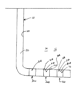
[0042] Referring to Figure 1, there is provided a flow control apparatus
100 for effecting
selective stimulation of a subterranean formation 14, such as a reservoir 16.
The flow control
apparatus 100 is deployable within a wellbore 10. Suitable wellbores 10
include vertical,
horizontal, deviated or multi-lateral wells.
[0043] The stimulation is effected by supplying treatment material to the
subterranean
formation which may include a hydrocarbon-containing reservoir.
[0044] In some embodiments, for example, the treatment material is a liquid
including
water. In some embodiments, for example, the liquid includes water and
chemical additives. In
other embodiments, for example, the treatment material is a slurry including
water, proppant, and
chemical additives. Exemplary chemical additives include acids, sodium
chloride,
polyacrylamide, ethylene glycol, borate salts, sodium and potassium
carbonates, glutaraldehyde,
guar gum and other water soluble gels, citric acid, and isopropanol. In some
embodiments, for
example, the treatment material is supplied to effect hydraulic fracturing of
the reservoir.
[00451 In some embodiments, for example, the treatment material includes
water, and is
supplied to effect waterflooding of the reservoir.
CA 02948027 2016-11-09
, =
[0046] In some embodiments, for example, the treatment material includes
water, and is
supplied for transporting (or "flowing", or "pumping") a wellbore tool (such
as, for example, a
plug) downhole.
[0047] The flow control apparatus 100 may be integrated within a wellbore
string 20 that
is deployable within the wellbore 10. Integration may be effected, for
example, by way of
threading or welding.
[0048] The wellbore string 20 may include pipe, casing, or liner, and may
also include
various forms of tubular segments, such as flow control apparatuses described
herein. The
wellbore string 20 defines a wellbore string passage 22.
[0049] Successive flow control apparatuses 100, 200, 300 may be spaced
from each
other within the wellbore string 20 such that each flow control apparatus 100,
200, 300 is
positioned adjacent a producing interval to be stimulated by fluid treatment
effected by treatment
material that may be supplied through a port (see below).
[0050] In some embodiments, for example, the flow control apparatus 100
includes a
housing 102. A passage 104 is defined within the housing 102. The passage 104
is configured
for conducting treatment material that is received from a supply source (such
as at the surface) to
a port 106 that extends through the housing 102.
[0051] In some embodiments, for example, the housing 102 includes
interconnected
upper and lower cross-over subs, and intermediate outer housing section. The
intermediate
housing section is disposed between the upper and lower crossover subs 102A,
102B. In some
embodiments, for example, the intermediate housing section is disposed between
the upper and
lower crossover subs, and is joined to both of the upper and lower crossover
subs with threaded
connections. Axial and torsional forces may be translated from the upper
crossover sub to the
lower crossover sub via the intermediate housing section.
[0052] The housing 102 is coupled (such as, for example, threaded) to
other segments of
the wellbore string 20, such that the wellbore string passage 22 includes the
housing passage
104. In some embodiments, for example, the wellbore string 20 is lining the
wellbore. The
wellbore string 20 is provided for, amongst other things, supporting the
subterranean formation
11
CA 02948027 2016-11-09
within which the wellbore is disposed. The welbore string may include multiple
segments, and
segments may be connected (such as by a threaded connection).
[0053] In some embodiments, for example, it is desirable to inject
treatment material into
a predetermined zone (or "interval") of the subterranean formation 14 via the
wellbore 10. In
this respect, the treatment material is supplied into the wellbore 10, and the
flow of the supplied
treatment material is controlled such that a sufficient fraction of the
supplied treatment material
(in some embodiments, all, or substantially all, of the supplied treatment
material) is directed, via
the port 106, to the predetermined zone. In some embodiments, for example, the
port 106
extends through the housing 102. During treatment, the port 106 effects fluid
communication
between the passage 104 and the subterranean formation 14. In this respect,
during treatment,
treatment material being conducted from the treatment material source via the
passage 104 is
supplied to the subterranean formation 14 via the port 106.
[0054] As a corollary, the flow of the supplied treatment material is
controlled such that
injection of the injected treatment material to another zone of the
subterranean formation is
prevented, substantially prevented, or at least interfered with. The
controlling of the flow of the
supplied treatment material, within the wellbore 10, is effected, at least in
part, by the flow
control apparatus 100.
[0055] In some embodiments, for example, conduction of the supplied
treatment to other
than the predetermined zone may be effected, notwithstanding the flow control
apparatus 100,
through an annulus, that is formed within the wellbore, between the casing and
the subterranean
formation. To prevent, or at least interfere, with conduction of the supplied
treatment material
to a zone of interval of the subterranean formation that is remote from the
zone or interval of the
subterranean formation to which it is intended that the treatment material is
supplied, fluid
communication, through the annulus, between the port 106 and the remote zone,
is prevented, or
substantially prevented, or at least interfered with, by a zonal isolation
material. In some
embodiments, for example, the zonal isolation material includes cement, and,
in such cases,
during installation of the assembly within the wellbore, the casing string is
cemented to the
subterranean formation, and the resulting system is referred to as a cemented
completion.
12
CA 02948027 2016-11-09
. =
[0056] To at least mitigate ingress of cement during cementing, and also
at least mitigate
curing of cement in space that is in proximity to the port 106, or of any
cement that has become
disposed within the port, prior to cementing, the port may be filled with a
viscous liquid material
having a viscosity of at least 100 mm2/s at 40 degrees Celsius. Suitable
viscous liquid materials
include encapsulated cement retardant or grease. An exemplary grease is SKF
LGHP 2TM
grease. For illustrative purposes below, a cement retardant is described.
However, it should be
understood, other types of liquid viscous materials, as defined above, could
be used in
substitution for cement retardants.
[0057] In some embodiments, for example, the zonal isolation material
includes a packer,
and, in such cases, such completion is referred to as an open-hole completion.
[0058] In some embodiments, for example, the flow control apparatus 100
includes the
flow control member 108. The flow control member 108 is displaceable, relative
to the port
106, such that the flow control member 16 is positionable in open and closed
positions. In this
respect, the flow control member 108 is displaceable relative to the port 106
for effecting
opening and closing of the port 106. The open position of the flow control
member 108
corresponds to an open condition of the port 106. The closed position of the
flow control
member 108 corresponds to a closed condition of the port 106.
[0059] In some embodiments, for example, in the closed position, the port
106 is covered
by the flow control member 108, and the displacement of the flow control
member 108 to the
open position effects at least a partial uncovering of the port 106 such that
the port 106 becomes
disposed in the open condition. In some embodiments, for example, in the
closed position, the
flow control member 108 is disposed relative to the port 106 such that a
sealed interface is
disposed between the passage 104 and the subterranean formation 30, and the
disposition of the
sealed interface is such that treatment material being supplied through the
passage 104 is
prevented, or substantially prevented, from being injected, via the port 106,
into the subterranean
foimation 30, and displacement of the flow control member 108 to the open
position effects fluid
communication, via the port 106, between the passage 104 and the subterranean
foimation 30,
such that treatment material being supplied through the passage 104 is
injected into the
subterranean formation 30 through the port 106. . In some embodiments, for
example, the sealed
13
CA 02948027 2016-11-09
interface is established by sealing engagement between the flow control member
108 and the
housing 102. In some embodiments, for example, "substantially preventing fluid
flow through
the port 106" means, with respect to the port 106, that less than 10 volume %,
if any, of fluid
treatment (based on the total volume of the fluid treatment) being conducted
through the passage
104 is being conducted through the port 106.
[0060] In some embodiments, for example, the flow control member 108
includes a
sleeve. The sleeve is slideably disposed within the passage 104. In some
embodiments, for
example, the sleeve has a generally cylindrical inner wall 108A. In some
embodiments, for
example, proximate its downhole end, the inner wall 108A has a taper in which
the inner
diameter increases in the downhole direction to define a seat 118 for
receiving engagement of a
seat-engaging member 119 of a plug 118, as is further described below.
[0061] In some embodiments, for example, the flow control member 108 is
displaceable
from the closed position to the open position and thereby effect opening of
the port 106. Such
displacement is effected while the flow control apparatus 100 is deployed
downhole within a
wellbore 10 (such as, for example, as part of a wellbore string 20), and such
displacement, and
consequential opening of the port 106, enables treatment material, that is
being supplied from the
surface and through the wellbore 10 via the wellbore string 20, to be injected
into the
subterranean formation 100 via the port 106. In some embodiments, for example,
by enabling
displacement of the flow control member 108 between the open and closed
positions, pressure
management during hydraulic fracturing is made possible.
[0062] In some embodiments, for example, the flow control member 108 is
displaceable
from the open position to the closed position and thereby effect closing of
the port 106.
Displacing the flow control member 108 from the open position to the closed
position may be
effected after completion of the supplying of treatment material to the
subterranean formation
100 through the port 106. In some embodiments, for example, this enables the
delaying of
production through the port 106, facilitates controlling of wellbore pressure,
and also mitigates
ingress of sand from the formation 100 into the casing, while other zones of
the subterranean
formation 100 are now supplied with the treatment material through other ports
106. In this
respect, after sufficient time has elapsed after the supplying of the
treatment material to a zone of
14
CA 02948027 2016-11-09
the subterranean formation 14, such that meaningful fluid communication has
become
established between the hydrocarbons within the zone of the subterranean
formation 14 and the
port 106, by virtue of the interaction between the subterranean formation 14
and the treatment
material that has been previously supplied into the subterranean formation 100
through the port
106, and, optionally, after other zones of the subterranean formation 100 have
similarly become
disposed in fluid communication with other ports 106, the flow control
member(s) may be
displaced to the open position so as to enable production through the
wellbore. Displacing the
flow control member 108 from the open position to the closed position may also
be effected
while fluids are being produced from the formation 100 through the port 106,
and in response to
sensing of a sufficiently high rate of water production from the formation 100
through the port
106. In such case, displacing the flow control member 108 to the closed
position blocks, or at
least interferes with, further production through the associated port 106.
[0063] The flow control member 108 is configured for displacement,
relative to the port
106, in response to application of a sufficient force. In some embodiments,
for example, the
application of a sufficient force is effected by a displacement-actuating
pressure differential that
is established across the flow control member 108. In some embodiments, for
example, the
sufficient force, applied to effect opening of the port 106 is a flow control
member opening
force, and the sufficient force, applied to effect closing of the port 106 is
a flow control member
closing force.
[0064] In some embodiments, for example, the housing 102 includes an
inlet 112. While
the apparatus 100 is integrated within the wellbore string 20, and while the
wellbore string 20 is
disposed downhole within a wellbore 10 such that the inlet 112 is disposed in
fluid
communication with the surface via the wellbore string 20, and while the port
106 is disposed in
the open condition, fluid communication is effected between the inlet 112 and
the subterranean
formation 30 via the port 106, such that the subterranean formation 30 is also
disposed in fluid
communication, via the port 106, with the surface (such as, for example, a
source of treatment
fluid) via the wellbore string 20. Conversely, while the port 106 is disposed
in the closed
condition, at least increased interference to fluid communication, relative to
that while the port
14 is disposed in the open condition (and, in some embodiments, sealing, or
substantial sealing,
of fluid communication), between the inlet 112 and the subterranean formation
30, is effected
CA 02948027 2016-11-09
such that the sealing, or substantial sealing, of fluid communication, between
the subterranean
formation and the surface, via the port 106, is also effected.
[0065] In some embodiments, for example, the housing 102 includes a
sealing surface
configured for sealing engagement with a flow control member 108, wherein the
sealing
engagement defines the sealed interface described above. In some embodiments,
for example,
the sealing surface is defined by sealing members. hi some embodiments, for
example, the flow
control member 108 co-operates with the sealing members to effect opening and
closing of the
port 106. When the port 106 is disposed in the closed condition, the flow
control member 108 is
sealingly engaged to both of the sealing members, and thereby preventing, or
substantially
preventing, treatment material, being supplied through the passage 104, from
being injected into
the reservoir 30 via the port 106. When the port 106 is disposed in the open
condition, the flow
control member 108 is spaced apart or retracted from at least one of the
sealing members (such
as the sealing member), thereby providing a passage for treatment material,
being supplied
through the passage 104, to be injected into the subterranean formation 30 via
the port 106. In
some embodiments, for example, each one of the sealing members, independently,
includes an o-
ring. In some embodiments, for example, the o-ring is housed within a recess
formed within the
housing 102. In some embodiments, for example, each one of the sealing
members,
independently, includes a molded sealing member (i.e. a sealing member that is
fitted within,
and/or bonded to, a groove formed within the sub that receives the sealing
member).
[0066] In some embodiments, for example, the port 106 extends through the
housing
102, and is disposed between the sealing surfaces.
[0067] In some embodiments, for example, the flow control apparatus 100
includes a
collet (not shown) that extends from the housing 102, and is configured to
releasably engage the
flow closure member 108 so as to provide resistance to its displacement from
selected positions
relative to the housing 102 (such as the open and closed positions) such that
a minimum
predetermined force is required to overcome this resistance to enable
displacement of the flow
control member between these selected positions.
[0068] In some embodiments, for example, while the apparatus 100 is being
deployed
downhole, the flow control member 108 is maintained disposed in the closed
position by one or
16
CA 02948027 2016-11-09
,
more shear pins. The one or more shear pins are provided to secure the flow
control member
108 to the wellbore string 20 (including while the wellbore string 20 is being
installed downhole)
so that the passage 104 is maintained fluidically isolated from the formation
100 until it is
desired to treat the formation 100 with treatment material. To effect the
initial displacement of
the flow control member 108 from the closed position to the open position,
sufficient force must
be applied to the one or more shear pins such that the one or more shear pins
become sheared,
resulting in the flow control member 108 becoming displaceable relative to the
port 106. In
some operational implementations, the force that effects the shearing is
applied by a pressure
differential.
[0069] The housing 102 additionally includes a shoulder 142 to limit
downhole
displacement of the flow control member 108.
[0070] In some embodiments, for example, the flow control member 108 is
configured
for displacement, relative to the port 106, in response to application of an
opening force that is
effected by fluid pressure. In some embodiments, for example, the opening
force is effectible
while pressurized fluid is disposed uphole of a plug 116 such that a
displacement-actuating fluid
pressure differential is established across the plug 116. In this respect, in
some embodiments,
for example, the flow control member 108 is configured for displacement,
relative to the port
106, in response to establishment of a displacement-actuating fluid pressure
differential across
the plug 116.
[0071] The plug 116 is fluid conveyable, and may take the form of a shape
that co-
operates with its deployment through the wellbore string 20.
[0072] In some embodiments, for example, the displacement-actuating fluid
pressure
differential, that is effectible across the plug 116, is effectible while the
plug 116 is disposed
within the passage 104 such that a sealed interface is defined within the
passage 104, and the
displacement-actuating fluid pressure differential, that is effectible across
the plug 116, includes
that which is effectible across the sealed interface. In this respect, the
flow control member 108
is configured for displacement, relative to the port 106, in response to
establishment of a
displacement-actuating fluid pressure differential across the sealed interface
that is defined
within the passage 104 while the plug 116 is disposed within the passage 104.
The disposition of
17
CA 02948027 2016-11-09
the sealed interface is such that, when pressurized fluid is supplied to the
passage 104, uphole of
the sealed interface, the displacement-actuating pressure differential is
established across the
sealed interface such that application of the opening force is effected such
that displacement of
the flow control member 108 in a downhole direction (in this case, to effect
opening of the port
106) is also effected. The sealed interface is with effect that sealing, or
substantial sealing, of
fluid communication between an uphole space 104A of the housing passage 104
and a downhole
space 104B of the housing passage 104 is effected. In some embodiments, for
example, the
sealed interface is defined by the sealing, or substantially sealing,
disposition of the plug 116
within the passage 104. In this respect, in some embodiments, for example, a
portion of the
external surface of the plug 116 is defined by a resilient material which
functions to enable the
plug to be conducted downhole through the wellbore string 20, while enabling
the sealing, or
substantially sealing, disposition of the plug 116 relative to the passage 104
to define the sealed
interface.
[0073] In some embodiments, for example, the establishment of the
displacement-
actuating pressure differential is effectible while the plug 116 is seated on
a seat 118 within the
apparatus 100. In this respect, in some embodiments, for example, the flow
control member 108
is configured for displacement, relative to the port 106, in response to
establishment of a
displacement-actuating fluid pressure differential across the plug 116, while
the plug 116 is
seated on the seat 118 that is defined within the apparatus 100.
[0074] In some embodiments, for example, the sealed interface, across
which the
displacement-actuating pressure differential is effectible for effecting the
displacement of the
flow control member 108, is effectible while the plug 116 is seated on the
seat 118. In this
respect, the flow control member 108 is configured for displacement, relative
to the port 106, in
response to establishment of a displacement-actuating fluid pressure
differential across the sealed
interface that is defined within the passage 104 while the plug 116 is seated
on the seat 118 that
is defined within the passage 104.
[0075] In some embodiments, for example, the seat 118 is defined as a
seat profile within
the apparatus 100, such as on the flow control member 108. In this respect, in
those
embodiments where the flow control member 108 is a sleeve, in some of these
embodiments, for
18
CA 02948027 2016-11-09
. .
example, the plug 116 is receivable within the seat 118 defined within the
sleeve for effecting
creation of the sealed interface.
[0076] Referring to Figures 2 to 8, amongst other things, in order to
avoid the use of
different sized plugs for effecting fluid treatment of multiple stages within
a subterranean
formation through ports whose manner of opening is as above-described, the
plug 116 includes a
seat-engaging member 119 (such as, for example, a "dog") that is deployable to
a seating-ready
condition such that the seat-engaging member 119 is disposed for being
displaced into
engagement with the seat 118 when the seat-engaging member 119 becomes aligned
with the
seat 118 while the plug 116 is being conducted through the housing passage
104. In this respect,
the plug 116 is co-operatively configured with the flow control apparatus 100
such that, while:
(i) the plug 116 is being conducted through the housing passage 104, and the
seat-engaging
member 119 is disposed in the seating-ready condition, when the seat-engaging
member 119
becomes aligned with the seat 118, the seat-engaging member 119 becomes
engaged to the seat
118 such that the plug 116 becomes seated on the seat 118. In some
embodiments, for example,
the engagement of the seat-engaging member 119 to the seat 118 is such that
the seat-engaging
member 119 becomes coupled to the seat 118, such as, for example, by becoming
landed on the
seat 118. In this respect, the plug 116 is co-operatively configured with the
apparatus 100 such
that, while: (i) the plug 116 is being conducted through the housing passage
104, and (ii) the
seat-engaging member 119 is disposed in the seating-ready condition, when the
seat-engaging
member 119 becomes aligned with the seat 118, the seat-engaging member 119
becomes
engaged to the seat 118 such that the plug 116 becomes seated on the seat 118.
In some
embodiments, for example, the seat-engaging member 119 becomes engaged to the
seat 118 by
displacement of the seat-engaging member 119. In some embodiments, for
example, the
displacement includes a lateral displacement relative to the axis of the
passage 104.
[0077] In the seating-ready condition, an applied force is being
transmitted to the seat-
engaging member 119. In this respect, while the seat-engaging member 119 is
disposed in the
seating-ready condition, when the seat-engaging member becomes aligned with
the seat 118, the
applied force effects the displacement of the seat-engaging member 119 into
the engagement
with the seat 118.
19
CA 02948027 2016-11-09
[0078] When the seat-engaging member 119 is not deployed in the seating-
ready
condition, the seat-engaging member 119 is disposed in a non-interference
condition such that,
while the plug 116 is being conducted through the passage 104, the seat-
engaging member 119
avoids becoming engaged to the seat 118 as the seat-engaging member 119 passes
by the seat
118, thereby permitting the plug 116 to be conducted further downhole of the
apparatus 100 so
as to become engaged to a seat of another apparatus that is disposed further
downhole, and
thereby effect fluid treatment of zones within the subterranean formation 14
that are disposed
further downhole. In this respect, the plug 116 is co-operatively configured
with the apparatus
100 such that, while: (i) the plug 116 is being conducted through the housing
passage 104, and
(ii) the seat-engaging member 119 is disposed in the non-interference
condition, the plug 116 is
conductible past the seat 118 (such as, for example, in the downhole
direction), such as, for
example, to the second apparatus.
[0079] The disposition of the seat-engaging member 119 is configured to
change from a
non-interference condition to a seating-ready condition in response to sensing
of a trigger
condition. In some embodiments, for example, while: (i) the plug 116 is being
conducted
through the wellbore string 20, and (ii) the seat-engaging member 119 is
disposed in the non-
interference condition, in response to the sensing of a trigger condition, the
seat-engaging
member 119 becomes disposed in the seating-ready condition. In this respect,
the seat-engaging
member 119 is deployable to a seating-ready condition in response to the
sensing of a trigger
condition. Also, in this respect, the plug 116 is co-operatively configured
with the flow control
apparatus 100 such that, while the plug 116 is being conducted through the
housing passage 104,
the seat-engaging member 119 is deployable to a seating-ready condition in
response to the
sensing of a trigger condition such that the seat-engaging member 119, of the
plug 116 being
conducted through the housing passage 104, is disposed in the seating-ready
condition, and
while: (i) the plug 116 is being conducted through the housing passage 104,
and (ii) the seat-
engaging member is disposed in the seating-ready condition, when the seat-
engaging member
119 becomes aligned with the seat 118, the seat-engaging member 119 engages
the seat 118 such
that the plug 116 becomes seated on the seat 118.
[0080] In some embodiments, for example, the trigger condition includes a
seating-
initiating profile 121 disposed within another apparatus disposed uphole
relative to the apparatus
CA 02948027 2016-11-09
. .
100 that includes the seat 118 which the seat-engaging member 119 is
configured to engage upon
deployment of the seat-engaging member 119 to the seating-ready condition in
response to
sensing of the trigger condition. In some embodiments, for example, and
referring to Figures 2A
to 2D and 3A to 3D, the seating-initiating profile is disposed within the
passage of the another
apparatus (such as apparatus 200) disposed uphole relative to the apparatus
100. In some
embodiments, for example, the seating-initiating profile is defined on the
flow control member
of the another apparatus disposed uphole relative to the apparatus 100. In
some embodiments,
for example, the seating-initiating profile includes a set of grooves disposed
on a passage-facing
surface of the flow control member of the another apparatus disposed uphole of
the apparatus
100.
[0081] In some embodiments, for example, while the seat-engaging member
119 is
disposed in the non-interference condition, the plug 116 is conductible past
the trigger such that
there is an absence of deployment of the plug 116 to the seating-ready
condition, such that the
plug 116 is conductible past the seat 118 of the next flow control apparatus
while being
conducted in a downhole direction within the wellbore string. In some
embodiments, for
example, while the seat-engaging member 119 is disposed in the non-
interference condition, the
plug 116 is conductible past the trigger such that, when the seat-engaging
member 119 becomes
aligned with the seat 118 of the next flow control apparatus, there is a
failure of engagement of
the seat-engaging member 119 to the seat 118 such that the plug 116 fails to
seat on the seat 118
of the next flow control apparatus while being conducted in a downhole
direction within the
wellbore string.
[0082] In some embodiments, for example, the change in disposition of the
seat-engaging
member 119, from the non-interference condition to the seating-ready
condition, which is
configured to be effected in response to the sensing of a trigger condition,
is effected by a seating
actuator 120 and the effecting of the change in disposition is in response to
the sensing of a
trigger condition and while the plug 116 is being conducted through the
housing passage 104 by
a pressurized fluid. While the seat-engaging member 119 is disposed in a
seating-ready
condition, the applied force is being transmitted by the seating actuator 120
to the seat-engaging
member 119, and when the seat-engaging member 119 becomes aligned with the
seat 118, the
applied force effects the displacement of the seat-engaging member 119 into
the engagement
21
CA 02948027 2016-11-09
. .
with the seat 118. In some embodiments, for example, the plug 116 includes the
seating actuator
120.
[0083] In some embodiments, for example, the seating actuator 120
includes a force
transmitter for effecting transmission of an applied force to the seat-
engaging member 119 for
effecting disposition of the seat-engaging member 119 in the seating-ready
condition.
[0084] In some embodiments, for example, the force transmitter includes a
fluid
communication device 160 and a pusher 162. In some embodiments, for example,
the pusher
162 includes a piston. The fluid communication device 160 is configured to
effect fluid
communication between the housing passage 104 and the pusher 162 while the
plug 116 is being
conducted through the housing passage 104 by a pressurized fluid such that the
pressurized fluid,
that is communicated from the housing passage 104, via the fluid communication
device 160, to
the pusher 162, applies a force to the pusher 162, that is transmitted by the
pusher 162 to the
seat-engaging member 119 such that the seat-engaging member 119 becomes
disposed in the
seating-ready condition. In some embodiments, for example, while disposed in
the seating-ready
condition that has being effected by the seating actuator 120, when the seat-
engaging member
119 becomes aligned with the seat 118, the pusher 162 urges displacement of
the seat-engaging
member 119 into engagement with the seat 118 such that the plug 116 becomes
seated on the
seat 118. In this respect, the pusher 162 is configured to urge displacement
of the seat-engaging
member 119, when the seat-engaging member 119 becomes aligned with the seat
while the seat-
engaging member 119 is disposed in the seating-ready condition, such that the
engagement of the
seat-engaging member 119 to the seat 118 is effected and such that the seating
of the plug 116 on
the seat 118 is effected.
[0085] In some embodiments, for example, the fluid communication device
160 includes
the fluid communication control valve 122 and the fluid communication passage
124. The fluid
communication passage 124 is provided for effecting fluid communication
between the housing
passage 104 and the pusher 162 such that a force is transmitted by the pusher
162 to the seat-
engaging member 119 for effecting disposition of the seat-engaging member 119
in the seating-
ready condition, and when the seat-engaging member 119 becomes aligned with
the seat 118, the
transmitted force urges the seat-engaging member 119 to become displaced into
engagement
22
CA 02948027 2016-11-09
with the seat 118 such that the plug 116 becomes seated on the seat 118. In
this respect, by
virtue of the fluid communication, the pressurized fluid within the housing
passage 104
communicates a force to the pusher 162, and this force is transmitted to the
seat-engaging
member such that disposition of the seat-engaging member 119 in the seating-
ready condition is
effected.
[0086]
The establishing of the fluid communication between the housing passage 104
and the pusher 162 is controlled by the positioning of the fluid communication
control valve 122
relative to the fluid communication passage 124. In this respect, the fluid
communication control
valve 122 is configured for displacement relative to the fluid communication
passage 124. The
displacement of the fluid communication control valve 122 is between a closed
position to an
open position. When the fluid communication control valve 122 is disposed in
the closed
position, sealing, or substantial sealing, of fluid pressure communication,
between the passage
104 and the pusher 162, via the fluid communication passage 124, is effected.
In some
embodiments, for example, when disposed in the closed position, the fluid
communication
control valve 122 is occluding the fluid communication passage 124. When the
fluid
communication control valve 122 is disposed in the open position and
pressurized fluid is
disposed within the passage 104, fluid communication is effected, via the
fluid communication
passage 124, between the passage 104 and the pusher 162 such that the
pressurized fluid within
the housing passage 104 communicates a force to the pusher 162, and this force
is transmitted to
the seat-engaging member such that disposition of the seat-engaging member 119
in the seating-
ready condition is effected.
[0087]
In some embodiments, for example, the sensing of the trigger condition effects
opening of the fluid communication control valve 122. In some embodiments, for
example, the
sensing of the trigger condition effects an application of a valve opening
force by a valve
actuator 164 for overcoming a biasing force that is urging disposition of the
fluid communication
control valve 122 to the closed position.
In this respect, the valve opening force effects
displacement of the fluid communication control valve 122 from the closed
position to the open
position. In some embodiments, for example, the biasing force, opposing the
opening of the
fluid communication control valve 122, is effected by a resilient member, such
as a spring. In
some embodiments, for example, the fluid communication control valve 122 may
be suitably
23
CA 02948027 2016-11-09
. .
pressure balanced such that the fluid communication control valve 122 is
disposed in the closed
position.
[0088]
In some embodiments, for example, the displacement of the fluid communication
control valve 122 is effectible by the valve actuator 164 in response to the
sensing of a trigger
condition.
[0089]
In some embodiments, for example, the valve actuator 164 includes a gas
generator that is electro-mechanically triggered to generate pressurized gas.
An example of such
an actuator 164 is a squib The squib is configured to, in response to the
sensing of a trigger
condition, effect generation of pressurized gas. In this respect, the
displacement of the fluid
communication control valve 122 is effected by the force applied by the
generated pressurized
gas. Another suitable actuator 164 is a fuse-able link or a piston pusher.
[0090]
In some embodiments, for example, the plug 116 further includes a sensor 128
and a controller 130. The sensor 128 is configured to sense the trigger
condition. The controller
130 is configured to receive a sensor-transmitted signal from the sensor 128
upon the sensing of
the trigger condition. In response to the received sensor-transmitted signal,
the controller 130
supplies an actuation signal to the valve actuator 164, and the valve actuator
164 effects (or
"triggers") the displacement of the fluid communication control valve 122. In
some
embodiments, for example, the controller 130 and the sensor 128 are powered by
a battery that is
also housed within the plug 116. In some embodiments, for example, the sensor
includes a Hall
effect sensor, a biased hall effect sensor, or a radio frequency
identification ("RFID") sensor.
[0091]
In some embodiments, for example, the seat-engaging member 119 is
displaceable, when the seat-engaging member 119 is disposed in the seating-
ready condition and
becomes aligned with the seat 118 while the plug 116 is being conducted
through the housing
passage 104, in a lateral direction (such as, for example, radially) relative
to the longitudinal axis
of the housing passage 104 by the applied force being transmitted by the
seating actuator 120 to
the seat-engaging member 119. In this respect, the engagement of the seat-
engaging member
119 with the seat 118 is effected by lateral displacement of the seat-engaging
member 119.
24
CA 02948027 2016-11-09
[0092] In some embodiments, for example, the seat-engaging member 119 is
positionable
relative to an external surface 116A of the plug 116 such that, when the seat-
engaging member
119 becomes laterally displaced such that the seat-engaging member 118 is
engaged to the seat
118, the seat-engaging member 119 is partially recessed into the external
surface 116A of the
plug 116 such that opposition to conduction of the plug 116 through the
housing passage 104 in a
downhole direction is effected and such that the seating of the plug 116 on
the seat 118 is thereby
effected. In this respect, in some embodiments, for example, the partial
recessing of the seat-
engaging member 119 is through a window 166 defined within a plug housing 168
of the plug
116, with the window 166 defining a shoulder 190. Also, in this respect, the
seat-engaging
member 119 is mounted within the window 166 such that the seat-engaging member
119 is
axially fixed, or substantially axially fixed, relative to the plug housing
168.
[0093] In some embodiments, for example, the plug housing 168 includes an
uphole
portion 170 and a downhole portion 172. The uphole portion 172 is partially
received by one
end of the downhole portion 170. In the illustrated embodiment, the window 166
is defined
through the downhole portion 170, and the seating actuator 120 includes the
fluid
communication device 160 and a pusher 162. The pusher 162 is mounted within
and
displaceable relative to the plug housing 168. The pusher 162 includes an
uphole end 162A
which fits around a downhole end 170A of the uphole portion 170 of the plug
housing 168. In
the illustrated embodiment, the pusher 162 is in the form of a sleeve. When
the pusher 162 is
disposed in an un-actuated condition, the uphole end 162A of the pusher is
abutting (or at least in
close proximity to) a radially outwardly-projecting shoulder 174 of the uphole
portion 170 of the
plug housing 168. The pusher 162 includes a radially outwardly-projecting
flange 176 that
engages the inner wall 178 of the uphole portion 170 of the plug housing 168.
The shoulder 174,
the flange 176, and the inner wall 178 of the uphole portion 170 co-operate to
define a chamber
180 to which fluid communication is effectible with the housing passage 104
via the fluid
communication passage 124, such that, when pressurized fluid is disposed
within the passage
104, fluid communication is effected, via the fluid communication passage 124,
between the
passage 104 and the chamber 180 such that the pressurized fluid within the
housing passage 104
communicates a force to the pusher 162, and this force is transmitted to the
seat-engaging
member such that disposition of the seat-engaging member 119 in the seating-
ready condition is
effected.
CA 02948027 2016-11-09
[0094] In some embodiments, for example, the pusher 162 and the plug
housing 168 are
co-operatively configured such that a low pressure chamber 181, that contains
a low pressure
fluid (such as a gas disposed at atmospheric pressure), is disposed between
the pusher 162 and
the plug housing 168, with effect that the area of the surface portion of the
pusher 162 that is
exposed to pressurized fluid within the wellbore, while fluid communication is
being effected
between the passage 104 and the chamber 180, is such that a sufficient force
imbalance is
effected across the pusher 162 (for example, in the downhole direction) such
that sufficient force
is transmitted to the seat-engaging member 119 for effecting the lateral
displacement of the seat-
engaging member 119 at a sufficiently fast rate to effect the engagement of
the seat-engaging
member 119 to the seat 118 when the seat-engaging member 119 becomes aligned
with the seat
118.
[0095] Referring to Figure 3A to 3D, in some embodiments, for example,
the pusher 162
includes a plurality of teeth 182. The teeth 182 are formed on the outer
surface of the pusher 162
proximate its downhole end. The teeth 182 have inclined cam surfaces 182A
which taper
inwardly in the downhole direction.
[0096] Also referring to Figure 3A to 3D, the seat-engaging surface 119
includes a
plurality of teeth 184 having inclined follower surfaces 184A corresponding to
the cam surfaces
182A and matingly engaging the teeth 182 of the pusher 162. While the seat-
engaging member
119 is non-aligned (i.e. out of alignment) relative to the seat 118, the flow
control member
retains the seat-engaging member 119 in a position such that the seat-engaging
member 119 is
disposed within the window 166 and the teeth 182, 184 interlock.
[0097] When the trigger is sensed by the sensor such that fluid
communication is effected
between the housing passage 104 and the chamber 180, fluid invades and
pressurizes the
chamber 180. This communicates a force to the pusher 162, and this force is
transmitted to the
seat-engaging member such that disposition of the seat-engaging member 119 in
the seating-
ready condition is effected. This force urges the pusher 162 in the downhole
direction, and the
teeth 182 of the pusher bear against the teeth 184 of the seat-engaging member
119, urging the
seat-engaging member 119 radially outwardly, and such displacement is resisted
by the flow
control member 108 (as described above), so long as there is an absence of
alignment between
26
CA 02948027 2016-11-09
. ,
the seat-engaging member 119 and the seat 118. In parallel, and by virtue of
the interlocking of
the teeth 182, 184 displacement of the pusher 162 relative to the housing is
resisted. This
condition of the plug is illustrated in Figures 3A to 3D and 4A to 4D, and the
seat-engaging
member 119 is disposed in the seating-ready condition.
[0098] Referring to Figures 5A to 5D, while the pusher 162 is
transmitting the applied
force to the seat-engaging member 119 (such that the seat-engaging member 119
is disposed in
the seating-ready condition), and when the seat-engaging member 119 becomes
aligned with the
seat 118, the opposition to lateral (for example, radial) displacement of the
seat-engaging
member 119 is removed. Accordingly, the cam surfaces 182A progressively
advance against the
follower surfaces 184A, and the shoulder 190 co-operates with the seat-
engaging member 119
while the cam surfaces 182A progressively advance against the follower
surfaces 184A such that
the lateral displacement of the seat-engaging member 119 into the engagement
with the seat 118
is effected and such that the seating of the plug 116 on the seat 118 is
effected. In parallel, the
pusher 162 is displaced downhole relative to the plug housing 168, eventually
bottoming out
against a stop 192. As mentioned above, because the seat-engaging member 119
is mounted
within the window 166 such that the seat-engaging member 119 is axially fixed,
or substantially
axially fixed, relative to the plug housing 168, when the seat-engaging member
119 is disposed
in engagement to the seat 118, the seat 118 functions to interfere with
conduction of the plug 116
in the downhole direction such that the plug 116 is seated on the seat 118.
[0099] Referring again to Figures 1A to 1D, in some embodiments, for
example, a
second flow control apparatus 200 and a third flow control apparatus 300 are
provided for
incorporation within the wellbore string 20 along with the flow control
apparatus 100. Each one
of the first, second and third flow control apparatuses, independently,
includes a respective
trigger condition. In some embodiments, for example, each one of the trigger
conditions,
independently, includes a seating-initiating profile defined within the
apparatus. Parts of the
second and third flow control apparatuses 200, 300 that are alike with parts
of the first flow
control apparatus 100 are labelled using the same reference numeral
incremented by "100".
With the exception of the trigger condition, the first, second and third flow
control apparatuses
200, 300 are identical, or substantially identical, to each other. Plugs 116
and 216 are also
provided. The plug 116 is configured for seating within the apparatus 100, as
described above.
27
CA 02948027 2016-11-09
. ,
The plug 216 is configured for seating within the apparatus 200, as described
above. The trigger
condition that, when sensed by the plug 116, while the plug 116 is being
conducted downhole
within the wellbore string 20, effects a change in condition of the plug 116
from the non-
interference condition to the seating-ready condition, is a "first trigger
condition", and the first
trigger condition is disposed within the second flow control apparatus 200,
downhole from the
second seat 218, such that the second flow control apparatus 200 includes the
first trigger
condition. The trigger condition that, when sensed by the plug 216, while the
plug is being
conducted downhole within the wellbore string 20, effects a change in
condition of the plug 216
from the non-interference condition to the seating-ready condition, is a
"second trigger
condition", and the second trigger condition is disposed within the third flow
control apparatus
200, downhole from the third seat 318, such that the third flow control
apparatus 200 includes
the second trigger condition.
[00100] In some embodiments, for example, a plug 316 is also provided and
is configured
for seating within the apparatus 300. The seating of the plug 316 is effected
in response to
sensing of a trigger condition (the "third trigger condition"), and in some of
these embodiments,
for example, the third trigger condition is disposed in another flow control
apparatus that is
disposed uphole relative to the third flow control apparatus 300. The third
flow control
apparatus 300 is, with the exception of the trigger condition, identical, or
substantially identical,
to each one of the flow control apparatuses 100, 200, 300, independently.
[00101] In some embodiments, for example, the first, second and third flow
control
apparatuses 100, 200, 300 are co-operatively configured such that, while
integrated within a
wellbore string 20 such that the second flow control apparatus 200 is disposed
uphole relative to
the first flow control apparatus 100, and the third flow control apparatus 300
is disposed uphole
relative to the second flow control apparatus 200, and while the plug 116 is
being conducted
through the wellbore string 20:
the plug 116 is conducted through the third flow control apparatus 300 without
having
become seated on the seat 318 of the third flow control apparatus 300;
28
CA 02948027 2016-11-09
. .
and after having been conducted through the third flow control apparatus 300,
the plug
216 is conducted through the second flow control apparatus 200 without having
becoming seated
on the seat 218 of the second flow control apparatus 200;
and after having been conducted through the second flow control apparatus 200,
and
while the plug is being conducted through the first flow control apparatus
100, the plug 116
becomes seated on the seat 118 of the first flow control apparatus 100.
and after the plug 116 has been conducted through the second flow apparatus
(such as, for
example, after the plug 116 has become seated on the seat 118), and while the
plug 216 is being
conducted through the wellbore string 20:
the plug 216 is conducted through the third flow control apparatus 300 without
having
become seated on the seat 318 of the third flow control apparatus 300;
and after having been conducted through the second flow control apparatus 300,
and
while the plug 216 is being conducted through the second flow control
apparatus 200, the plug
216 becomes seated on the seat 218 of the second flow control apparatus 200.
[00102] In some embodiments, for example, the size of the second plug is
greater than,
equal to, or substantially equal to the size of the second plug. In some
embodiments, for
example, the first plug has the same, or substantially the same, dimensions as
the second plug.
[00103] In some embodiments, for example, the first, second and third flow
control
apparatuses 100, 200, 300 are co-operatively configured such that, while
integrated within a
wellbore string 20 such that the second flow control apparatus 200 is disposed
uphole relative to
the first flow control apparatus 100, and the third flow control apparatus 300
is disposed uphole
relative to the second flow control apparatus 200, and while the plug 116 is
being conducted
through the wellbore string 20:
the plug 116 is conducted through the third flow control apparatus 300 without
having
effected deployment of the seat-engaging member 119 to the seating-ready
condition, such that
the plug 116 is conducted through the third flow control apparatus without
having become seated
on the seat 318 of the third flow control apparatus 300;
29
CA 02948027 2016-11-09
and after having been conducted through the third flow control apparatus 300,
the plug is
conducted through the second flow control apparatus 200 without having
effected deployment of
the seat-engaging member 119 to the seating-ready condition until at least
after the seat-engaging
member 119 has passed the seat 218, such that the plug 116 is conducted
through the second
flow control apparatus 200 without haying become seated on the seat 218 of the
second flow
control apparatus 200;
and after the seat-engaging member 119 has passed the seat 218, and before
haying
passed the seat 118 of the first flow control apparatus 100, in response to
sensing of the first
trigger condition disposed within the second flow control apparatus 200, the
seat-engaging
member 119 becomes deployed in the seating-ready condition;
and after having been conducted through the second flow control apparatus 200,
and
while being conducted through the first flow control apparatus 100 with the
seat-engaging
member 119 deployed in the seating-ready condition, the plug 116 becomes
seated on the seat
118 of the first flow control apparatus 100;
and after the plug 116 has been conducted through the second flow apparatus
(such as, for
example, after the plug 116 has become seated on the seat 118), and while the
plug 216 is being
conducted through the wellbore string 20:
the plug 216 is conducted through the third flow control apparatus 300 without
having
effected deployment of the seat-engaging member 219 to the seating-ready
condition until at
least after the seat-engaging member 219 has passed the seat 318, such that
the plug 216 is
conducted through the third flow control apparatus without having become
seated on the seat 318
of the third flow control apparatus 300;
and after the seat-engaging member 219 has passed the seat 318, and before
having
passed the seat 218 of the second flow control apparatus 200, in response to
sensing of the
second trigger condition disposed within the third flow control apparatus 300,
the seat-engaging
member 219 becomes deployed in the seating-ready condition;
and after haying been conducted through the second flow control apparatus 300,
and
while being conducted through the second flow control apparatus 200 with the
seat-engaging
CA 02948027 2016-11-09
. .
member 219 deployed in the seating-ready condition, the plug 216 becomes
seated on the seat
218 of the second flow control apparatus 200.
[00104] In some embodiments, for example, the plug 116 is configured to
ignore the
second trigger condition of the third apparatus 300.
[00105] In some embodiments, for example, the ignoring of the second
trigger condition
by the plug 116 is such that the plug 116 is conductible past the second
trigger condition such
that there is an absence of deployment of the plug 116 to the seating-ready
condition, such that
the plug 116 is conductible past the second flow control apparatus 200 while
being conducted in
a downhole direction within the wellbore string.
[00106] In some embodiments, for example, the ignoring of the second
trigger condition
by the plug 116 is such that the plug 116 is conductible past the second
trigger condition such
that, when the seat-engaging member 119 becomes aligned with the seat 218,
there is a failure of
engagement of the first-engaging member 119 to the seat 218 such that the plug
116 fails to seat
on the seat 218 while being conducted in a downhole direction within the
wellbore string.
[00107] In some embodiments, for example, the ignoring of the second
trigger condition
by the plug 116 is such that the plug 116 is conductible past the second
trigger condition such
that there is an absence of deployment of the plug 116 to the seating-ready
condition such that,
when the seat-engaging member 119 becomes aligned with the seat 118, there is
a failure of
engagement of the seat-engaging member 119 to the seat 118 such that the plug
116 fails to seat
on the seat 118, such the plug 116 is conductible past the second flow control
apparatus 200
while being conducted in a downhole direction within the wellbore string.
[00108] It is understood that additional flow control apparatuses may be
incorporated
within the wellbore string 20, and that such additional flow control
apparatuses may be identical,
or substantially identical, to the first, second and third flow control
apparatuses 100, 200, 300,
with the exception that the trigger condition of each one of the flow control
apparatuses,
independently, is different.
[00109] In another aspect, a kit may also be provided, and include the
first, second and
third flow control apparatuses 100, 200, 300, and also include the plug 116.
In some
31
CA 02948027 2016-11-09
embodiments, for example, the kit also includes the plug 216, and, in some
embodiments, for
example, the plug 316. It is understood that additional flow control
apparatuses may be
incorporated within the kit, as well as corresponding plugs, and that such
additional flow control
apparatuses may be identical, or substantially identical, to the first or
second flow control
apparatuses 100, 200, with the exception that the trigger condition of each
one of the flow
control apparatuses is different.
[00110] An exemplary process for supplying treatment fluid to a
subterranean formation,
through a wellbore string 20, disposed within a wellbore, and incorporating
any one of the
above-described embodiments of the flow control apparatus, will now be
described.
[00111] The plug 116 is conducted downhole (such as being pumped with
flowing fluid)
through the wellbore string 20 (disposed within the wellbore 10) including the
first, second and
third flow control apparatuses 100, 200, 300 (as described above). The second
flow control
apparatus 200 is disposed uphole relative to the first flow control apparatus
100. The third flow
control apparatus 300 is disposed uphole relative to the second flow control
apparatus 200.
When introduced into the wellbore string, the plug 116 is disposed in the non-
interference
condition.
[00112] The plug 116 is conducted through the third flow control apparatus
300 without
having effected deployment of the seat-engaging member 119 to the seating-
ready condition,
such that the plug 116 is conducted through the third flow control apparatus
without having
become seated on the seat 316 of the third flow control apparatus 300. After
having been
conducted through the third flow control apparatus 300, the plug 116 is
conducted through the
second flow control apparatus 200 without having effected deployment of the
seat-engaging
member 119 to the seating-ready condition until at least after the seat-
engaging member 119 has
passed the seat 218, such that the plug 116 is conducted through the second
flow control
apparatus 200 without having become seated on the seat 216 of the second flow
control
apparatus 200. Referring to Figures 2A to 2D, while being conducted through
the second flow
control apparatus 200, the plug 116 senses the first trigger condition
(embodied in the trigger
221) within the second flow control apparatus 200, such as with the on-board
sensor 128. In
response, the seat-engaging member 119 is deployed (in accordance with any one
of the
32
CA 02948027 2016-11-09
embodiments described above), such that the seat-engaging member 119 becomes
disposed in
the seating-ready condition before the seat-engaging member 119 passes the
seat 118 within the
first flow control apparatus 100 (see Figures 3A to 3D). After having been
conducted through
the second flow control apparatus 200, the plug 116 is received within the
first flow control
apparatus 100 with the seat-engaging member 119 deployed in the seating-ready
condition (see
Figures 4A to 4D). Referring to Figures 5A to 5D, while being conducted
through the first flow
control apparatus 100 with the seat-engaging member 119 deployed in the
seating-ready
condition, the plug 116, via the seat-engaging member 119, becomes seated on
the seat 118 of
the first flow control apparatus 100. Once the plug 116 is seated on the seat
118, pressurized
fluid is supplied uphole of the seated first plug 116 such that the flow
control member 108 of the
first apparatus 100 becomes displaced to the open position (see Figures 6A to
6D). Treatment
fluid is then supplied to the subterranean formation through the first port
106 to effect treatment
of the zone of the subterranean formation in the vicinity of the port 106.
After the treatment is
completed, the supplying of the treatment fluid is suspended.
[00113]
After the supplying of the treatment fluid has been suspended, the plug 216 is
introduced into the wellbore string 20 and is conducted downhole through the
wellbore string 20.
When introduced into the wellbore string 20, the plug 216 is disposed in the
non-interference
condition. The plug 216 is conducted through the third flow control apparatus
300 without
having effected deployment of the seat-engaging member 219 to the seating-
ready condition
until at least after the seat-engaging member 219 has passed the seat 318,
such that the plug 216
is conducted through the third flow control apparatus 300 without having
become seated on the
seat 316 of the third flow control apparatus 300. While being conducted
through the second flow
control apparatus 200, the plug 216 senses the second trigger condition, such
as with the on-
board sensor 128. In response, the seat-engaging member 219 is deployed (in
accordance with
any one of the embodiments described above), such that the seat-engaging
member 219 becomes
disposed in the seating-ready condition before the seat-engaging member 219
passes the seat 218
within the second flow control apparatus 200. After having been conducted
through the second
flow control apparatus 300, and while being conducted through the second flow
control
apparatus 200 with the seat-engaging member 219 deployed in the seating-ready
condition, the
plug 216, via the seat-engaging member 219, becomes seated on the seat 218 of
the second flow
control apparatus 200. Once the plug 216 is seated on the seat 218,
pressurized fluid is supplied
33
CA 02948027 2016-11-09
uphole of the seated second plug 216 such that the flow control member 208 of
the second
apparatus 200 becomes displaced to the open position. Treatment fluid is then
supplied to the
subterranean formation through the port 206 to effect treatment of the zone of
the subterranean
formation in the vicinity of the port 206. After the treatment is completed,
the supplying of the
treatment fluid is suspended.
1001141 This process may be repeated with additional combinations of flow
control
apparatuses and plugs, and, in some embodiments, with additional combinations
of flow control
apparatuses and plugs that are co-operatively configured such that the plug
ignores trigger
conditions of all flow control apparatuses that are disposed uphole relative
to the flow control
apparatus within which the plug is intended to be seated so as to effect the
opening of the port
(the "corresponding flow control apparatus), with the exception of the flow
control apparatus that
is disposed immediately uphole of the corresponding flow control apparatus. In
this way, the
same size plug could be used to effect treatment of multiple zones, such that
the number of zones
being treated within the subterranean formation is not limited in the same
manner as it is with
conventional ball drop systems..
[00115] After the subterranean formation has been sufficiently treated
with treatment
fluid, in accordance with the process as above-described, it is desirable to
effect flow back and,
therefore, production of the hydrocarbon material from the reservoir of the
subterranean
formation. In some embodiments, for example, in order to effect flowback, the
plugs 116, 216
may be milled out, thereby creating fluid communication between the open ports
118, 218 and
the wellhead.
[00116] In other embodiments, for example, the plug 116 may be suitably
designed to
enable flowback. In this respect, in some embodiments, for example, the plug
116 includes a
passage 132 that is occluded by a dissolvable closure 134 such that, while the
plug 116 is seated
on the seat 118, fluid flow is prevented, or substantially prevented, through
the passage 132,
between a portion of the wellbore string 20 that is disposed downhole relative
to the plug 116
and a portion of the wellbore string 20 that is disposed uphole relative to
the plug 116. The
dissolvable closure 134 is configured to dissolve within wellbore fluids, such
that fluid
communication between the downhole and uphole wellbore portions have been
established, after
34
CA 02948027 2016-11-09
a time interval that is sufficient to enable treatment of all the desired
zones with the wellbore
string 20 (see Figures 7A to 7D). After the closure 134 has dissolved,
flowback may be
implemented. In some embodiments, for example, the material of construction of
the dissolvable
closure 134 includes.
[00117] In some embodiments, for example, the plug 116 is further
configured to mitigate
the risk of premature dissolving of the dissolvable closure 134. If the
dissolvable closure 134
dissolves prior to the opening of the port 106, then the displacement-
actuating fluid pressure
differential cannot be established across the plug 116 unless another way of
occluding the
passage 132 is provided. In this respect, and referring to Figures 8A to 8D,
in some
embodiments, for example, the plug 116 includes a seat 194 within the passage
132 for landing
of a ball 196 on the seat 194, such that the ball 196 is seated on the seat
194 and thereby occludes
the passage 132, and thereby enables the establishment of the displacement-
actuating fluid
pressure differential.
[00118] In some embodiments, for example, the plug 116, itself, is
dissolvable, for
purposes of flowback. Figure 9 illustrates a condition of the flow control
apparatus 100 after the
plug 116 having been dissolved.
[00119] In some embodiments, for example, the flow control apparatus 100
is co-
operatively designed with the plug 116 to provide "anti-rotation" features for
mitigating rotation
of the plug 116 relative to the flow control apparatus 100 during milling
operations, such as
those performed to effect flowback. It is understood that these features may
be provided with the
flow control apparatus / plug combinations 200/216 and 300/316, as well as all
other flow
control apparatus / plug combinations that are used within the wellbore
system.
[00120] In some embodiments, for example, with respect to the seat-
engaging member
119, the flow control apparatus 100 (such as, for example, and more
specifically, the flow
control member 108) includes grooves, and the seat-engaging member 119 is
configured, when
seated on the seat 118, to key into grooves such that interference to rotation
of the plug 116,
relative to the axis of the passage 104, is effected, such that the plug 116
is disposed for being
milled out by a milling tool. In some embodiments, for example, the
interference is such that the
rotation is prevented or substantially prevented.
CA 02948027 2016-11-09
. .
[00121]
As above-described, in some embodiments, for example, and referring to Figures
6A to 6D, the plug 116 includes the plug housing 168, and the plug housing 168
includes a
downhole housing portion 170 and an uphole housing portion 172. The downhole
housing
portion 170 defines a downhole end 170A, and the uphole housing portion 172
defines an uphole
end 172A. The downhole end 170A defines seat-engaging members 170B configured
to key into
a downhole end of another identical, or substantially identical plug. The
downhole and uphole
housing portions 170, 172 are co-operatively configured such that, while the
seat-engaging
member 119 is seated on the seat 118, the seat-engaging member 119 is retained
between the
downhole and uphole housing portions 170, 172. In this respect, during milling
operations, after
the seat-engaging member 119 has been milled out, the downhole portion is
pushed down to a
plug that is disposed immediately downhole, and the downhole portion keys into
the uphole end
of such plug so as to enable milling of the downhole portion 136.
[00122]
In the above description, for purposes of explanation, numerous details are
set
forth in order to provide a thorough understanding of the present disclosure.
However, it will be
apparent to one skilled in the art that these specific details are not
required in order to practice
the present disclosure.
Although certain dimensions and materials are described for
implementing the disclosed example embodiments, other suitable dimensions
and/or materials
may be used within the scope of this disclosure. All such modifications and
variations, including
all suitable current and future changes in technology, are believed to be
within the sphere and
scope of the present disclosure. All references mentioned are hereby
incorporated by reference
in their entirety.
36