Note: Descriptions are shown in the official language in which they were submitted.
81800218
- 1 -
Nebulizer
The present invention relates to a nebulizer as described herein .
WO 2012/162305 Al discloses a nebulizer. A container can be inserted into a
housing of the nebulizer. The housing is closed by a lower housing part. By ro-
tating the housing part the drive spring can be put under tension and fluid
can be
sucked into a compression chamber of the pressure generator. Simultaneously,
the container is moved into the lower housing part in a stroke movement within
the nebulizer and when tensioned for the first time the container may be
pierced
through its base by a piercing element in the lower housing part to allow
venting
of the container. After manual pressing a button, the drive spring is released
and
moves the delivery tube into the pressure chamber so that the fluid is put
under
pressure by the drive spring and is delivered or atomized through a nozzle
into a
mouthpiece as an aerosol, without the use of propellant gas. Thus, the
container
is moving axially forth and back during conveying of the fluid to be
nebulized,
and during pressure generation and nebulization.
The container may be connected inseparably with the housing part by a securing
device forming a transportation lock for holding the container unmovable in a
de-
livery state.
The nebulizer comprises an indicator device for counting and/or indicating a
number of uses performed or still possible. The indicator device blocks
further
use in a locked state when a predetermined number of uses has been reached
or exceeded with the current container. Then, the container can be replaced to-
gether with a housing part and the nebulizer can be used further with the new
container.
US 7,823,584 B2 discloses a similar nebulizer, wherein a counter device can be
integrated into a housing part that is exchangeable or replaceable together
with
the container, which is inseparable from the housing part. The nebulizer com-
prises a locking device for blocking the lower housing part and an inner
housing
part against further rotation in a second locked state after a predetermined
num-
ber of containers has been used to finally lock the nebulizer against any
further
use. This locking device comprises a spring as locking element which radially
engages into an upper housing part of the nebulizer to block any further
rotation
Date recue / Date received 2021-11-22
81800218
- 2 -
when the nebulizer has been tensioned for the last time. The rotational
locking
cannot be unlocked again.
WO 2007/104694 Al discloses an inhaler for powdery substances with an indi-
Gator device which may comprise a worm gear for driving an indicator element.
Object of the present invention is to provide a nebulizer allowing easy and/or
se-
cure operation and handling and/or a compact and/or reliable construction,
pref-
erably while allowing replacement of the container without replacement of any
io housing part of the nebulizer.
The above object is achieved by a nebulizer as described herein.
The present invention relates to a nebulizer for nebulizing a fluid,
preferably liq-
uid medicament, from a preferably replaceable container containing the fluid.
Preferably, an indicator device is provided for counting and/or indicating the
number of uses already performed or still possible with the container.
In particular, the indicator device controls or causes a locking device to
lock
the nebulizer against further use in a locked state when a predetermined
number
of uses has been reached or exceeded with the respective container.
Preferably,
the nebulizer comprises a housing part which can be detached from the nebuliz-
er or opened for replacing the container.
In particular, the locking device or a locking element thereof is adapted to
block
any (further) rotation of the nebulizer, in particular of a lower or
detachable
and/or inner housing part relative to an upper housing part of the nebulizer.
Thus, the nebulizer cannot be tensioned or prepared for the next use, so that
e.g. any pumping or dispensing of fluid is prevented, when the rotation is
blocked in the locked state. In particular, (complete) tensioning is necessary
for
preparing the nebulizer for next use, i.e. next nebulization of fluid.
According to one aspect of the present invention, the locking device or
locking
element is adapted to block the rotation preferably before a complete
tensioned
state or position of the nebulizer is reached and/or in an intermediate
position or
partially tensioned state, most preferably in the second half of the total
rotation
angle necessary for (completely) tensioning the nebulizer. This allows easy
Date recue /Date received 2021-11-22
CA 02948066 2016-11-04
WO 2015/169428 PCT/EP2015/000900
- 3 -
and/or secure operation and handling. In particular, any further dispensing of
flu-
id can be directly prevented when the locked state is entered as the nebulizer
or
its drive spring cannot be (completely) tensioned.
According to a further aspect of the present invention, the container is
replacea-
ble preferably only in an at least partially tensioned state of the nebulizer
such
that complete closing of the nebulizer or its housing is not possible when the
in-
dicator device is in the locked state. This allows easy and/or secure
operation
and handling. In particular, a user can easily realize that the indicator
device
lo preferably together with the container has to be changed and cannot be
reused
when the nebulizer cannot be closed.
According to another preferred aspect of the present invention, a locking ele-
ment of the locking device axially engages by form-fit and/or with multiple,
pref-
erably rib-like engagement portions into respective pockets or vice versa in a
locking position' to block the rotation. This allows secure operation and/or
simple
construction, wherein a very quick locking can be achieved even if the
nebulizer
or its housing part is rotated with high speed. Further, a simple construction
or
easy operation for unlocking or release are possible.
According to a further aspect of the present invention, the locking device com-
prises preferably an axially moveable locking member interacting with the lock-
ing element via an inclined surface for radially moving the locking element
pref-
erably outwards into the locking position. Alternatively or additionally, the
locking
element is formed by or comprises a sliding block. The locking element or
sliding
block is preferably (only) radially moveable. This allows secure operation
and/or
simple construction, wherein a very quick locking can be achieved even if the
nebulizer or its housing part is rotated with high speed. Further, a simple
con-
struction or easy operation for unlocking or release are possible.
According to another aspect of the present invention, the locking device
and/or
locked state can preferably be reset to release or unlock the rotation
locking.
This allows replacement of the container and indicator device, wherein the
nebu-
lizer and its housing part can be reused, while a very secure locking and,
thus,
secure operation can be realized in the locked state.
CA 02948066 2016-11-04
WO 2015/169428 PCT/EP2015/000900
- 4 -
Preferably the container cannot be used anymore in the locked state when the
indicator device has detected that a predetermined number of uses has been
reached or exceeded, in particular with the respective container.
The indicator device may either directly or indirectly lock or initiate or
trigger
locking of the nebulizer and/or container against further use. In particular,
the in-
dicator device may directly actuate the locking device or indirectly initiate
actua-
tion of the locking device. Preferably, the indirect actuation is realized by
means
or via at least partial opening of the nebulizer or its housing or housing
part in
order to lock the nebulizer against further use with the current container.
Preferably, the nebulizer is blocked (automatically) against further use or
ten-
sioning if the nebulizer housing or housing part is at least partially open or
opened or if, with other words, when the nebulizer or its housing is not (corn-
pletely) closed.
It is also possible that the nebulizer is not immediately blocked against
further
use when the indicator device enters the locked state. Instead, the indicator
de-
vice may initiate or cause or trigger in its locked state that the locking
device is
going to block the nebulizer against further use, e.g. during the next
actuation or
tensioning or the like. Thus, the locking device may enter its locking state
later,
e.g. after at least partial opening of the nebulizer and/or at least partial
tension-
ing of the nebulizer or rotation of the housing part or inner part of the
nebulizer
or the like.
Therefore, the blocking of the nebulizer can be initiated or caused by the
indica-
tor device not only indirectly, but alternatively or additionally also later
during fur-
ther handling, operation, actuation or the like. In the latter case, the
indicator de-
vice blocks or initiates or causes blocking of the nebulizer and/or container
against further use also preferably in the sense of the present invention.
Preferably, the locking of the nebulizer against further use can be overcome
by
replacing the container, in particular including the indicator device, against
one
not yet used.
Preferably, the indicator device is inseparably connected with the container
or
with a container housing of the container, but separable from the nebulizer or
its
housing and from the housing part, so that the indicator device is replaceable
81800218
- 5 -
together with the container. This allows reuse of the nebulizer and the
housing part with
another container including another indicator device. Thus the overall size of
the
components to be exchanged is kept small, so that the replacement packages are
size
reduced, so that transport of a large number of packages is facilitated.
Preferably, the indicator device is fixedly arranged at a bottom of the
container and/or
opposite to an outlet of the container. This allows a very compact
construction. Further, the
indicator device does not interfere with the fluidic connection of the
container to the
nebulizer or vice versa.
In one particular embodiment, there is provided a nebulizer for a fluid, the
nebulizer
comprising: an upper housing part; a lower or detachable housing part; a
replaceable or
insertable container containing the fluid; an indicator device for counting or
indicating a
number of uses performed or still possible with the container; and a locking
device adapted
to block further use of the nebulizer or container in a locked state when a
predetermined
number of uses has been reached or exceeded with the current container;
wherein the
nebulizer is tensioned or prepared for next use by a rotation of the lower or
detachable
housing part relative to the upper housing part of the nebulizer, such
rotation about a
predetermined total rotation angle being necessary for the nebulizer reaching
a complete
tensioned state for the next use of the nebulizer, wherein the locking device
or a locking
element thereof is adapted to block the rotation of the lower housing part at
an intermediate
rotational position after initiating the rotation of the lower housing part
but before reaching
the predetermined total rotation angle, and thereby before reaching the
complete tensioned
state of the nebulizer, and wherein the locking device comprises a movable
locking element
and a locking spring associated with the locking element, wherein the locking
element is
biased into a locking position by the locking spring.
The above aspects of the present invention and the further aspects described
below can
be realized independently from each other, and in any combination.
Date Recue/Date Received 2022-06-28
81800218
- 5a -
Further advantages, features, characteristics and aspects of the present
invention will
become apparent from the claims and the following description of preferred
embodiments
with reference to the drawings. It shows:
Fig. 1 a schematic section of a known nebulizer in a non-tensioned
state;
Fig. 2 a schematic section, rotated 90 compared with Fig. 1, of the known
nebulizer
in a tensioned state; Fig. 3 a
schematic section of a nebulizer with an
inserted container in a non-tensioned state according to a preferred
embodiment of the present invention;
Fig. 4 a partial enlargement of the encircled part of Fig. 3;
Fig. 5 a perspective view of the section of the nebulizer according to Fig.
3;
Fig. 6 an enlargement of the encircled part of Fig. 5;
Fig. 7 a schematic exploded view of an indicator device according to a
preferred
embodiment of the present invention;
Fig. 8 an axial section of the indicator device in an actuated state;
Date Recue/Date Received 2022-06-28
CA 02948066 2016-11-04
WO 2015/169428 PCT/EP2015/000900
- 6 -
Fig. 9 an axial section of the indicator device in a locked state;
Fig. 10 a perspective section of the indicator device in an actuated
state;
Fig. 11 a perspective section of the indicator device in an released
state;
Fig. 12 a partial enlargement of the nebulizer similar to Fig. 4, but
in a par-
tially tensioned state;
Fig. 13 a partial enlargement of the nebulizer similar to Fig. 4, but
in a fully
tensioned state;
Fig. 14 a partial section of the nebulizer similar to Fig. 4, but in
an interme-
diate state during a dispensing stroke;
Fig. 15 a partial section of the nebulizer similar to Fig. 4, but with
an indica-
tor device of the container in a locked state;
Fig. 16 a schematic section of the nebulizer in the locked state after next
tensioning with partially opened housing part and with locked lock-
ing device;
Fig. 17 a partial enlargement of the encircled part of Fig. 13;
Fig. 18 a schematic section of the nebulizer similar to Fig. 3 with
unlocked
locking device;
Fig. 19 a schematic section of the indicator device in the initial
state ac-
cording to a modified embodiment;
Fig. 20 a perspective section of the indicator device according to
Fig. 19;
Fig. 21 a schematic side view of the nebulizer in the area of the
encircled
part of Fig. 16, but in an unlocked position and with partially
opened upper housing part;
CA 02948066 2016-11-04
WO 2015/169428 PCT/EP2015/000900
- 7 -
Fig. 22 a schematic partial section of the locking device in the
locking posi-
tion shown in Fig. 16 and 17 in a radial plane;
Fig. 23 a partial schematic section of the nebulizer with unlocked
locking
device according to another embodiment;
Fig. 24 a perspective section of the nebulizer with the unlocked
locking de-
vice according to a further embodiment; and
o Fig. 25 a schematic section similar to Fig, 24 with the locking device
in the
locking position.
In the Figures, the same reference numerals are used for identical or similar
parts, resulting preferably in corresponding or comparable properties and ad-
is even if the associated description is not repeated.
Figs. 1 and 2 show a known nebulizer 1 for atomizing a fluid 2, particularly a
highly effective pharmaceutical composition, medicament or the like, diagram-
matically shown in a non-tensioned state (Fig. 1) and in a tensioned state
(Fig.
20 2). The nebulizer 1 is constructed in particular as a portable inhaler
and prefera-
bly operates only mechanical and/or without propellant gas.
When the fluid 2, preferably a liquid, more particularly a pharmaceutical
compo-
sition, is nebulized, an aerosol 14 (Fig. 1) is formed or dispensed, which can
be
25 breathed in or inhaled by a user. Usually the inhaling is done at least
once a
day, more particularly several times a day, preferably at set intervals,
depending
on the complaint or illness from which a patient is suffering.
The nebulizer 1 is provided with or comprises an insertable or replaceable con-
tamer 3 containing the fluid 2. The container 3 thus forms a reservoir for the
fluid
2, which is to be nebulized. Preferably, the container 3 contains multiple
doses
of fluid 2 or active substance in particular sufficient to provide up to 200
dosage
units or doses, for example, i.e. to allow up to 200 sprays or applications. A
typi-
cal container 3, as disclosed in WO 96/06011 Al, holds e.g. a volume of about
2
35 to 20 ml.
Further, the number of doses contained in the container 3 and/or the total vol-
ume of the fluid 2 contained in the container 3 can vary depending on the
fluid 2
CA 02948066 2016-11--04
WO 2015/169428 PCT/EP2015/000900
- 8 -
or respective medicament and/or depending on the container 3 and/or depend-
ing on the necessary medication or the like.
Preferably, the container 3 can be replaced or exchanged, wherein the total
number of uses of the nebulizer 1 and thus the number of containers 3, which
can be used with the same nebulizer 1, is preferably restricted, e.g. to a
total
number of four or five containers 3. WO 2012/162305 Al discloses additionally
such a restriction to the total numbers of containers 3 which can be used with
the same nebulizer 1.
lo
The container 3 is preferably substantially cylindrical or cartridge-shaped
and
once the nebulizer 1 has been opened the container 3 can be inserted therein
preferably from below and changed if desired, It is preferably of rigid
construc-
tion, the fluid 2 in particular being held in a collapsible bag 4 in the
container 3.
In particular, the container 3 comprises a venting opening or hole 23 which is
opened before or during first use.
The nebulizer 1 comprises a delivery mechanism, preferably a pressure genera-
tor 5, for conveying and nebulizing the fluid 2, particularly in a preset and
option-
ally in an adjustable dosage amount.
The nebulizer 1 or pressure generator 5 comprises preferably a holder 6 for re-
leasably holding the container 3, a drive spring 7 associated to the holder 6,
only
partly shown, and/or a blocking element 8 preferably in form of or with a
button
for preferably manual actuation or depressing. The blocking element 8 can
catch
and block the holder 6 and can be manually operated to release the holder 6 al-
lowing drive spring 7 to expand.
The nebulizer 1 or pressure generator 5 comprises preferably a conveying ele-
ment, such as a conveying tube 9, a non-return valve 101 a pressure chamber
11 and/or an nozzle 12 for nebulizing the fluid 2 into a mouthpiece 13.
The completely inserted container 3 is fixed or held in the nebulizer 1 via
the
holder 6 such that the conveying element fluidically connects the container 3
to
the nebulizer 1 or pressure generator 5. Preferably, the conveying tube 9 pene-
trates into the container 3.
CA 02948066 2016-11-04
WO 2015/169428 PCT/EP2015/000900
- 9 -
The nebulizer 1 or holder 6 is preferably constructed so that the container 3
can
be exchanged.
When the drive spring 7 is axially tensioned in the tensioning process, the
holder
6 with the container 3 and the conveying tube 9 are moved downwards in the
drawings and fluid 2 is sucked out of the container 3 into the pressure
chamber
11 of the pressure generator 5 through the non-return valve 10. In this state,
the
holder 6 is caught by the blocking element 8 so that the drive spring 7 is
kept
compressed. Then, the nebulizer 1 is in the tensioned state.
During the subsequent relaxation in the nebulization process after actuation
or
pressing of the blocking element 8 the fluid 2 in the pressure chamber 11 is
put
under pressure as the conveying tube 9 with its now closed non-return valve 10
is moved back in the pressure chamber 11, here in the drawings upwards, by
the relaxation or force of the drive spring 7 and now acts as a pressing ram
or
piston. This pressure forces the fluid 2 through the nozzle 12, whereupon it
is
nebulized into the aerosol 14, as shown in Fig. 1, and, thus, dispensed.
Generally, the nebulizer 1 operates with a spring pressure of 5 to 200 MPa,
preferably 10 to 100 MPa on the fluid 2, and/or with a volume of fluid 2
delivered
per stroke of 10 to 50 pl, preferably 10 to 20 pl, most preferably about 15
pl. The
fluid 2 is converted into or nebulized as aerosol 14, the droplets of which
have
an aerodynamic diameter of up to 20 pm, preferably 3 to 10 pm. Preferably, the
generated jet spray has an angle of 20 to 160 , preferably 80 to 100 . These
values also apply to the nebulizer 1 according to the teaching of the present
in-
vention as particularly preferred values.
A user or patient (not shown) can inhale the aerosol 14, preferably while an
air
supply can be sucked into the mouthpiece 13 through at least one optional air
supply opening 15.
The nebulizer 1 comprises preferably a housing 24 and/or (upper) housing part
16 and optionally a biasing or inner part 17 preferably which is rotatable
relative
thereto (Fig. 2) and/or has an upper part 17a and a lower part 17b (Fig. 1).
The nebulizer 1 or housing 24 comprises preferably a (lower) housing part 18.
This part 18 is in particular manually operable, and/or releasable fixed,
particu-
CA 02948066 2016-11-04
WO 2015/169428 PCT/EP2015/000900
- 10 -
lady fitted or held onto the inner part 17, preferably by means of a retaining
ele-
ment 19.
Preferably, the housing parts 16 and 18 and/or other parts form the housing 24
of the nebulizer 1.
In order to insert and/or replace the container 3, preferably the housing 24
can
be opened and/or the housing part 18 can be detached from the nebulizer 1, in-
ner part 17 or housing 24.
Generally and preferably, the container 3 can be inserted before the housing
24
is closed and/or before the housing part 18 is connected to the housing 24.
The
container 3 may be inserted, opened and/or fluidically connected to the
delivery
mechanism automatically or simultaneously when (completely) connecting the
housing part 18 to the housing 24 / nebulizer 1 and/or when (completely)
closing
the housing 24 / nebulizer 1. Preferably, the container 3 is open or
fluidically
connected when tensioning the nebulizer 1 for the first time with the current
con-
tainer 3.
Preferably, the nebulizer 1 or drive spring 7 can be manually activated or ten-
sioned or loaded, in particular by actuation of an actuation member, here
prefer-
ably by rotating housing part 18 or any other component.
The actuation member, preferably the housing part 18, can be actuated, here ro-
tated relative to the upper housing part 16, carrying with it or driving the
inner
part 17. The inner part 17 acts on a gear or transmission to transform the
rota-
tion in an axial movement. As a result the drive spring 7 is tensioned in the
axial
direction by means of the gear or transmission (not shown) formed between the
inner part 17, in particular its upper part 17a, and the holder 6 and acting
on the
holder 6. During tensioning the container 3 is moved axially downwards until
the
container 3 assumes an end position as shown in Fig. 2. In this activated or
ten-
sioned state the drive spring 7 is under tension and can be caught or held by
the
blocking element 8. During the nebulizing process the container 3 is moved
back
into its original position (non-tensioned position or state shown in Fig. 1)
by (the
force of) the drive spring 7. Thus the container 3 executes a lifting or
stroke
movement during the tensioning process and during the nebulizing process.
CA 02948066 2016-11-04
WO 2015/169428 PCT/EP2015/000900
- 11 -
The housing part 18 preferably forms a cap-like lower housing part and/or fits
around or over a lower free end portion of the container 3. As the drive
spring 7
is tensioned the container 3 moves with its end portion (further) into the
housing
part 18 or towards the end face thereof, while an aeration means, such as an
ax-
ially acting spring 20 arranged in the housing part 18, comes in contact with
base 21 of the container 3 and pierces the container 3 or a base seal or foil
50
thereon with a piercing element 22 when the container 3 makes contact with it
for the first time, to allow air in or aeration, preferably by opening or
piercing
venting hole 23. The venting hole 23 allows for pressure compensation inside
o the container 3 when fluid 2 is drawn from the container 3 during the
actuation of
the nebulizer 1.
The nebulizer 1 comprises preferably an indicator device 25, which counts in
particular actuations of the nebulizer 1, preferably by detecting its
tensioning or
the rotation of the inner part 17 relative to the upper part 16 or housing 24.
Pref-
erably, the counter device 25 or an associated locking device 26 locks the
nebu-
lizer 1 against (further) actuation or use, e.g. blocks further rotation of
the hous-
ing part 18 / inner part 17 and, thus, tensioning of the nebulizer 1 or its
drive
spring 7 and/or blocks actuation of the blocking element 8, in a locked state
when a certain number of actuations or operations or discharged doses has
been reached or exceeded.
In particular, the locking device 26 is controlled or controlable by the
indicator
device 25.
In the following and with reference to the further figures, a preferred
embodiment
of the nebulizer 1, container 3, indicator device 25 and/or locking device 26
is
described and shown according to the invention, wherein primarily important as-
pects and differences will be described and the previous aspects, features and
313 explanations apply preferably additionally or correspondingly even
without repe-
tition.
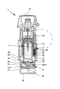
Fig. 3 shows the nebulizer 1 with the container 3 and indicator device 25
accord-
ing the present invention in a schematic section (longitudinal section) in the
non-
tensioned state with completely closed nebulizer housing 24 and, thus, closed
housing part 18, wherein the container 3 including the proposed indicator
device
25 are inserted into or received within the nebulizer 1 and/or housing 24.
CA 02940066 2016-11-04
WO 2015/169428 PCT/EP2015/000900
- 12 -
Fig. 4 shows an enlarged partial section of the encircled part of Fig. 3. Fig.
5
shows a perspective view of the section of the nebulizer 1 of Fig. 3. Fig. 6
shows
a partial enlargement of the encircled part of Fig. 5.
The nebulizer 1 has preferably a longitudinal form or axis which corresponds
to
the axial direction and/or to the main dispensing direction and/or to stroke
movement of the container 3 during tensioning and dispensing.
In the shown non-tensioned state, the nebulizer 1 or its mouthpiece 13 is
prefer-
o ably closed by a mouthpiece cover 27. The mouthpiece cover 27 is
preferably
pivotable to allow opening of the mouthpiece 13 for using the nebulizer 1.
Preferably, the indicator device 25 is directly and/or unreleasably secured or
fixed to or connected with the container 3. In particular, the indicator
device 25 is
associated to a respective container 3. If the container 3 of the nebulizer 1
is re-
placed, the indicator device 25 is necessarily or positively replaced as well.
Preferably, the indicator device 25 is fixedly arranged at the bottom or
container
base 21 of the container 3 and/or opposite to an outlet or head 28 of the con-
tainer 3.
In the present embodiment, the indicator device 25 is preferably directly con-
nected to or abuts at an outer case or preferably rigid housing 29 of the
contain-
er 3.
Preferably, the indicator device 25 and the container 3 are connected by form-
fit
and/or snap-fit.
In particular, the indicator device 25 circumvents and/or grips over a (lower
or
bottom) edge 30 and/or any other protrusion or the like of the container 3. In
the
present embodiment, the edge 30 is a little bit wider in diameter so that it
pro-
trudes radially over the essentially cylindrical outer form of the side wall
of the
container 3 / container housing 29.
The diameter of the indicator device 25 is preferably at least essentially
equal to
or slightly greater than the diameter of the container 3 or its edge 30.
CA 02948066 2016-11-04
WO 2015/169428 PCT/EP2015/000900
- 13 -
The edge 30 is preferably formed between the side wall and the bottom or base
21 of the container 3 or container housing 29. Preferably, the edge 30 is
formed
by flanging, bordering, bending or crimping or by any other suitable material-
deforming process.
The indicator device 25 comprises a housing 31 and/or preferably has an at
least essentially cylindrical form.
The indicator device 25 or its housing 31 is preferably attached to the
container
lo 3 or its base 21 or housing 29 with an at least essentially flat and/or
axial side.
The indicator device 25 or its housing 31 comprises preferably a holding or
grip-
ping section 32 for connecting the indicator device 25 with the container 3.
Pref-
erably, the gripping section 32 circumvents the edge 30 and/or grips around or
over the edge 30.
In the present embodiments, the gripping section 32 is preferably annular
and/or
grips over the edge 31 at positions distributed over the circumference of the
edge 30 or container 3.
Preferably, the indicator device 25 and the container 3 are connected with
each
other by a snap-fit or click connection. Preferably, the container 3 and the
indica-
tor device 25 are connected with each other by axially snapping one part on
the
other.
Preferably, the gripping section 32 is sufficiently elastic in radial
direction so that
the container 3 can be entered axially with its edge 30. In the present embodi-
ment, the gripping section 32 preferably comprises a respectively inclined
inser-
tion face to facilitate insertion of edge 30 into the annular gripping section
32 or
between circumferentially distributed gripping sections 32.
It has to be noted that other constructional solutions are possible for
connecting
the container 3 or its housing 29 with the indicator device 25 or its housing
31 or
vice versa. In particular, the two parts can be connected with each other addi-
tionally or alternatively by welding, brazing, gluing, screwing, clamping, hot-
pressing, or the like.
CA 02948066 2016-3.1-04
WO 2015/169428 PCT/EP2015/000900
- 14 -
Fig. 7 shows in a schematic, exploded view the indicator device 25 according
to
the preferred embodiment of the present invention.
The indicator or its housing 31 comprises preferably an upper part 33 and a
low-
er part 34.
Preferably, the upper part 33 holds or forms the gripping section 32.
The indicator device 25 comprises preferably an indicator element 35 and an
associated actuation element 36 and/or a transmission 40 or gear 41 for index-
ing the indicator element 35 or for causing the indexing of the indicator
element
35.
The indicator device 25 is for counting and/or indicating a number of uses per-
formed or still possible with the respective or associated container 3.
Preferably,
the indicator element 35 comprises markings 37, such as one or more symbols,
numbers, coloured or shaded areas or the like, for at least roughly indicating
the
number of uses already performed with or still possible with the respective
con-
tainer 3. In the present embodiment, the indicator element 35 is preferably
rotat-
able and/or comprises a circumferential wall or outer surface with the at
least
one marking 37.
The indicator housing 31 comprises preferably a window 31a, in particular in
the
circumferential wall through the relevant marking 37 is visible for a user or
pa-
tient, preferably through the housing part 18 which is in particular
transparent.
The actuation element 36 comprises preferably an actuation arm 38 which, in-
tern comprises preferably a free or actuation end 39, for direct or indirect
actua-
tion or indexing of the indicator element 35. Indexing means that the
indicator
element 35 is moved forward in increments or steps.
Preferred is an indirect actuation or driving so that the actuation element 36
or
its arm 38 actuates or drives the indicator element 35 via a transmission 40.
In
the present embodiment, the transmission 40 results in a reduction and/or is
re-
alized as a worm device.
The indicator device 25 or transmission 40 comprises preferably a gear 41
and/or a worm 42. Most preferably, the worm 42 is directly formed by the gear
CA 02948066 2016-11-04
WO 2015/169428 PCT/EP2015/000900
- 15 -
41 so that the gear 41 forms a worm gear and preferably comprises radially pro-
truding teeth 43 in which at least one convolution of the worm 42 is formed
(compare the horizontal or axial sections of the mounted indicator device 25
shown in Figs. 8 and 9).
The gear 41 comprises preferably an axle, in particular one or more axle sec-
tions 44 which may axially protrude on opposite sides as realized in the
present
embodiment.
o The actuation element 36 causes a rotation of the gear 41 around an axis
pref-
erably perpendicular to the direction of movement of the actuation element 36,
the axis preferably being arranged in a horizontal plane identical or parallel
to
the plane given by the movement of the actuation element 36.
The gear 41 is rotatably held preferably by the housing 31 or lower housing
part
34, preferably by two bearing sections 45 of the lower part 34. Preferably,
the
bearing sections 45 comprises recesses for rotatably holding the axle sections
44. However, other constructional solutions are possible as well.
The housing 31 or lower part 34 bears preferably the indicator element 35 such
that it can rotate. In the present embodiment, the lower part 34 comprises
pref-
erably two bearing portions 46 arranged on opposite radial sides and axially
pro-
truding for rotatably bearing the indicator element 35. The actuation element
35
and/or transmission 40 are preferably arranged at least essentially in between
the bearing portions 46.
The indicator device 25 comprises preferably an actuation spring 47, in
particu-
lar for biasing the actuation element 36 into a preferred direction and/or for
driv-
ing the indicator element 35
Fig. 8 shows in a horizontal or axial section the mounted indicator device 25
in
an actuated state where the actuation element 36 has been moved or pushed
sidewards, namely starting from the first position shown in Figs. 3 to 6
towards
the left into a second position which is shown in Fig. 8.
Fig. 9 shows in a similar section as Fig. 8 the indicator device 25 in a
locked
state where the actuation element 36 is in a locked, third position.
CA 02948066 2016-3.1-04
WO 2015/169428 PCT/EP2015/000900
- 16 -
It can been seen from Figs. 8 and 9 that protrusions 60 of the indicator
element
35 (not shown in Figs. 8 and 9) extend axially, wherein always at least one
pro-
trusion 60 is caught in the worm 42 so that a worm drive is formed between the
gear 41 and the indicator element 35. Thus, any rotation of gear 41 is trans-
formed in a reduced rotation of the indicator element 35. Further, a permanent
engagement between the gear 41 and the indicator element 35, more precisely
between at least one protrusion 60 and the worm 42, is ensured. However, other
constructional solutions or couplings between the gear 41 and the indicator
ele-
ment 35 are possible.
lo
Fig. 10 shows the mounted indicator device 25 in a perspective section in the
ini-
tial, first position and state. Fig. 11 shows the indicator device 25 in a
similar
perspective section, but with released actuation element 36, i.e. just before
the
locked state is reached.
Preferably, the transmission 40 or gear 41 forms a worm (helical groove) 42
with
at least one convolution, preferably a with about 1.5 or more convolutions, so
that always at least one engaging element of the indicator element 35 or of
any
other transmission component, in particular the inwardly or axially projecting
pro-
trusion 60, engages in the worm 42. Thus, rotation of the gear 41 around its
preferably transversal axis results in a rotation of the indicator element 35
around its preferably longitudinally oriented rotation axis. However, other
con-
structional solutions are possible as well.
Preferably, the teeth 43 are relatively long and/or extend radially
sufficiently so
that the protrusions are securely guided within the convolutions of the worm
42,
in between the teeth 43, and that the actuation portion 39 can still move in
radial
direction between the protrusion 60 engaging into the worm 42 and the gear 41
in order to actuate or rotate the gear 41 in the desired manner. For this
purpose,
the actuation portion 39 may engage into respectively deep cut outs between
the
teeth 43 in order to be able to move below the respective projection 60.
The indicator device 25 comprises preferably a piercing part 48 (compare Fig.
3
to 6).
The piercing part 48 is arranged within the indicator device 25 or its housing
31.
The piercing part 48 is preferably axially moveable.
CA 02948066 2016-11-04
WO 2015/169428 PCT/EP2015/000900
- 17 -
The piercing part 48 is preferably moveable such that it can protrude towards
the
container 3 and/or can open an aeration opening, preferably the venting hole
23,
of the container 3, in particular by breaking or piercing a foil 50 covering
the
venting hole 23.
In the present embodiment, the piecing element 48 comprises preferably an
opening end or tip 49 which can open or pierce the foil 50 covering the
container
base 21, in particular an indention 51 formed in the container 3 or its base
21.
Preferably, the indention 51 comprises a break through which forms the venting
hole 23. However, other constructional solutions are possible as well.
Fig. 12 shows in a partial enlargement similar to Fig. 4 a lower portion of
the
nebulizer 1 in an intermediate state after partial tensioning. The indicator
device
25 is in an actuated state as shown in Fig. 8 (second position).
The nebulizer 1 or housing part 18 comprises preferably a driving part 52 for
driving or actuating the indicator device 25 when using the nebulizer 1, in
partic-
ular for actuating the indicator device 25 in response to any tensioning of
the
nebulizer 1 and/or any (axial or stroke-like) movement of the container 3.
Preferably, the driving part 52 is arranged or formed in the housing part 18,
in
particular on the axial end face or bottom 53 of the housing part 18.
Preferably, the driving part 52 is arranged centrally and/or extends axially.
Preferably, the driving part 52 is at least substantially cylindrical and/or
pin-like
or bolt-like.
Preferably, the driving part 52 is held by the housing part 18 and/or
integrally
formed by the housing part 18.
In the preferred embodiment, the movement of the container 3 and, thus, of the
indicator device 25 during the tensioning (downward movement in the drawings)
and/or during pressurization and dispensing (upward movement in the drawings)
and/or one or both of the respective end positions in the non-tensioned state
and
tensioned state, respectively, can be used for actuating the indicator device
25,
i.e. for counting.
CA 02948066 2016-11-04
WO 2015/169428 PCT/EP2015/000900
- 18 -
Preferably, the relative movement of the container 3 and/or indicator device
25
within the nebulizer 1, and more preferred the movement during dispensing, is
used for actuating or triggering the indicator device 25 and/or counting.
When tensioning the nebulizer 1 and/or moving the indicator device 25 down-
wards, the driving part 25 enters or engages through an insertion opening 54
of
the indicator device 25 or its housing 31, in particular axially.
Preferably, the driving part 52 and the insertion opening 54 are arranged
central-
ly and/or axially aligned.
In the present embodiment, the driving part 52 actuates the actuation element
36, i.e. moves the actuation element 36 from an initial first position shown
in Fig.
3 to 6, to an actuated second position shown in Fig. 9.
Preferably, the actuation spring 47 biases the actuation element 36 into the
first
position.
In the present embodiment, the actuation element 36 is moveable back and forth
between the first and second positions for indexing the indicator element 35,
in
particular for incrementally rotating the gear 41 in one direction to
respectively
drive the indicator element 35. As any rotation of gear 41 is transformed in a
re-
duced rotation of the indicator element 35, thus every movement of the
actuation
element 36 from the first to the second position or vice versa results in a
move-
ment of the indicator element 35.
In the present embodiment, the actuation element 36 is moveable transversally,
preferably perpendicularly, to the longitudinal or dispensing direction of the
con-
tamer 3 or nebulizer 1 and/or to the stroke movement of the container 3 and/or
indicator device 25.
Preferably, the actuation element 36 is moved from the more central first posi-
tion radially outwards to the second position, in particular against the force
of the
associated, preferably helical actuation spring 47 biasing the actuation
element
36 in opposite direction.
CA 02948066 2016-11-04
WO 2015/169428 PCT/EP2015/000900
- 19 -
In the second position, the actuation element 36 has been moved with its actua-
tion arm 38 or actuation portion 39 out of engagement with gear 41 as
indicated
in Figs. 8 and 12.
Fig. 13 shows in a similar enlarged section as Fig. 12 the fully tensioned
state.
In the (fully) tensioned state, the container 3, more precisely the aeration
open-
ing or venting hole 23, is opened at least when the nebulizer 1 is tensioned
with
a container 3 for the first time.
Preferably, the opening of the container 3 or venting hole 23 for aeration is
real-
ized by piercing or breaking, in particular of foil 50.
The opening or piercing can be effected directly by the driving part 52.
Alterna-
tively, the opening or piercing can be effected independently from the driving
part 52, e.g. by means of the aeration spring 20 with the piercing element 22
similar to the embodiment shown in Fig. 2. Alternatively, as in the present em-
bodiment, the opening or piercing can be achieved indirectly, preferably via
the
piercing part 48 which is preferably actuated by the driving part 52.
Preferably, the piercing part 48 is formed as separate part and/or provided by
the indicator device 25 and/or arranged within the indicator device 25.
In the preferred embodiment, the piercing part 48 is held axially moveable by
a
support structure 55 of the indicator device 25, housing 31, upper part 32
and/or
indicator element 35, as schematically indicated in Figs. 10 and 11.
Preferably, the piercing part 48 and/or the support structure 55 are a one-
piece-
construction with a further part of the indicator devices 25, e.g. with the
indicator
element 35 or with the indicator housing 31, especially with the upper part 33
of
the indicator housing 31.
Preferably, the piercing part 48, support structure 55 and the further part of
the
indicator device 25 are made of plastic in an injection molding process.
Preferably, the support structure 55 comprises flexible arms or ribs for
holding
the piercing part 48 axially moveable.
CA 02948066 2016-11-04
WO 2015/169428 PCT/EP2015/000900
- 20 -
Alternatively the piercing part 48 can be constructed as separate, axially
movea-
ble part, which is optionally spring biased in the longitudinal or axial
direction
away from the container 3, so that the piercing tip 49 is retracted from the
con-
tainer 3 in the non-tensioned state.
It has to be noted that the piercing part 48 or its tip 49 is preferably
received
within the indicator device 25 or its housing 31, but can protrude outwards in
the
actuated state.
io The opening or piercing can be repeated each time the nebulizer 1 is
tensioned,
i.e. each time when the container 3 reaches its end position in the tensioned
state.
The piercing part 48 may be biased into its retracted or initial position
shown in
Fig. 3 to 6, in particular by a preferably integrally formed biasing arm,
spring or
the like, preferably by the support structure 55.
The piercing part 48 may comprise a compensation portion, such as a flexible
arm 56, for compensating any tolerances in axial direction. Such tolerances
can
occur in particular due to variations during production, in particular
variations of
the length of the container 3 and/or other components, variations of the
connec-
tions of the container 3 with the indicator device 25, variations of the
length of
the indicator device 25 or its housing 31, variations of the axial position of
the
container 3 within the holder 6, and the like. Thus, different distances
between
the free end of driving part 52 and the counter-face of the piercing part 48
can
result. The construction is such that the driving part 52 and the piercing
part 48
cooperate in any case such that the desired piercing is ensured.
The compensation portion allows axial compression ¨ here by radial flexing of
arms 56 ¨ when a predetermined axial force is exceeded in order to avoid any
damage of the container 3 and/or any other component of the nebulizer 1. Thus,
in the preferred embodiment the driving part 52 first moves the piercing part
48
towards the container base 21 into the piercing position and further axial
move-
ment of the driving part 52 is compensated by the compensation portion, prefer-
ably by the flexible arms 56 being spread radially outwards, giving way to the
tip
of the driving part 52 for entering a central recess in the piercing part 48
(on the
side opposite to the piercing tip 49).
CA 02948066 2016-11-04
WO 2015/169428 PCT/EP2015/000900
-21 -
The piercing part 48 comprises preferably at least one axial channel, in
particu-
lar one or more axially extending grooves 57 circumferentially distributed
around
the circumference of tip 49, in order to ensure unblocked aeration or venting
even if the piercing part 48 stucks or stays in the foil 50 or piercing
position.
Fig. 14 shows in a similar enlargement as Fig. 4, 12 and 13 an intermediate
state of the pressurization or dispensing process, i.e, when the container 3
has
been moved partially upwards again. In this state, the driving part 52 has
been
withdrawn from the indicator device 25 or through the insertion opening 54 par-
lo tially such that the actuation element 36 starts to return to its
initial or first posi-
tion due to the force of the actuation spring 47. Finally, after sufficient
withdrawal
of the driving part 52, the actuation element 36 returns into the first
position
shown in Figs. 3 to 6 when the back movement is completed.
The back movement of the container 3 and/or of the actuation element 36 actu-
ates preferably the indicator device 25 or gear 41 and/or is detected or
counted.
In particular, the actuation element 36 or its arm 38 or actuation portion 39
transmits the back movement or movement from the second to the first position
to the transmission 40. In particular, this movement causes an incremental
rota-
tion of gear 41.
Thus, in the present embodiment, the movement of the container 3 and/or indi-
cator device 25 within the nebulizer 1 during dispensing is preferably used
for
actuating or triggering the indicator device 25 and/or for counting.
In the present embodiment, the actuation arm 38 or its portion 39 abuts
against
one tooth 43 of gear 41 during the back movement and, thus, turns the gear 41
due to the back movement one step further, in the drawings in clockwise direc-
tion.
Preferably, the indicator device 25 comprises a ratchet 58 preventing any coun-
ter-rotation of the transmission 40 or gear 41. Into the present embodiment,
the
ratchet 58 is formed by a flexible arm extending from the housing 31, in
particu-
lar lower housing part 34, and/or meshing with or engaging into the gear 41 or
its
teeth 43.
CA 02948066 2016-11-04
WO 2015/169428 PCT/EP2015/000900
- 22 -
In the end position, i.e. in the non-tensioned state, the driving part 52 is
prefera-
bly further or completely retracted from the indicator device 25, the
indicator
housing 31 and/or insertion opening 54 as shown in Fig. 3 to 6.
The transmission 40 or gear 41 transforms the actuation, in particular the
(back-
ward) movement of the actuation element 36 or its arm 38 / actuating portion
39,
into an indexing of the indicator element 35. The transmission ratio or
transmis-
sion function of the transmission 40 or gear 41 may be designed or constructed
such that a reduction or non-linear driving or indexing is achieved. In the
present
embodiment, the transmission 40 or gear 41 forms preferably a worm drive for
achieving a desired reduction.
The movement of the actuation element 36 ¨ in particular from the first
position
to the second position ¨ results in that the actuation arm 38 or its actuation
por-
tion 39 are moved out of engagement with the gear 41, in particular can be
pulled over the next tooth 43. Hereby, the arm 38 is flexed out. The
subsequent
movement in opposite direction, i.e. the back movement or movement from the
second to the first position, results in that the actuation arm 38 or its
actuation
portion 39 contacts the next tooth 41 and can transmit the at least essential
line-
ar movement of the arm 38, more precisely the preferably linear movement of
the actuation element 36, into a rotation of the gear 41, more precisely in an
in-
dexing of gear 41 by preferably one tooth 43.
Preferably, the teeth 43 are asymmetrical, i.e. comprise differently inclined
shoulders on one side and the other side in order to facilitate and/or ensure
the
incremental actuation and movement in one rotational direction by the back and
forth movement and engagement of the actuation arm 38.
Preferably, the actuation element 36 is linearly moveable and/or forms a
sliding
carriage.
Preferably, the actuation element 36 is supported and/or held moveably by the
housing 31, in particular lower part 34 of the housing 31. However, other con-
structional solutions are possible as well.
The actuation spring 47 acts preferably between the housing 31 or lower part
34
on one hand and the actuation element 36 on the other hand.
CA 02948066 2016-11--04
WO 2015/169428 PCT/EP2015/000900
- 23 -
In the present embodiment, the spring 47 is preferably already compressed
and/or biased in the first position and/or biases the actuation element 36
such
that it at least partially closes or blocks the insertion opening 54.
Preferably, the actuation element 36 comprises an inclined gliding surface 59
at
its part protecting into or over the insertion opening 32 in the first
position. This
surface 59 is inclined such that the insertion of the driving part 52, i.e.
its axial
movement or abutment, is transformed into a transversal or radial movement of
the actuation element 36.
lo
Alternatively or additionally, such a surface 59 can also be formed at the
driving
part 52 to achieve the desired transformation of the axial movement into a
trans-
versal or radial movement by means of an inclined plane.
Therefore, the actuation or rotation of the transmission 40 or gear 41 is
prefera-
bly effected by the force of the actuation spring 47 or any other pressure or
en-
ergy store or spring means. This results in the advantage that no additional
force
is necessary for driving the indicator device 25 or its indicator element 35.
Con-
sequently, the pressurization and dispensing process is not disturbed.
Further, the triggering of the counting or actuation of the transmission 40 /
gear
41 is effected preferably by the pressurization or dispensing process or move-
ment, i.e. during the actual dispensing of fluid 2, i.e. usually during actual
use or
inhalation.
The actuation spring 47 biases the actuation element 36 preferably towards
closing the insertion opening 54.
Usually, the movement of the actuation element 36 is restricted so that it
does
not completely close the insertion opening 54 before the locked state is
reached.
This limitation is realized in the present embodiment preferably via a control
means or portion 62 against which a control part 63 abuts in particular to
restrict
the back movement of the actuation element 36 at the first position.
The abutment is shown in particular in Fig. 10. However, other constructional
so-
lutions are possible as well.
CA 02948066 2016-3.1-04
WO 2015/169428 PCT/EP2015/000900
- 24 -
After the number of uses of the nebulizer 1 with the container 3 has reached
or
exceeded a predetermined number of uses as detected or registered by the in-
dicator device 25, a locked state is entered and the nebulizer 1 will be
locked
against further use with the current container 3 and/or the container 3 will
be
locked against further use with the nebulizer 1.
In particular, the indicator device 25 comprises a blocking part 61 which
blocks
further use of the container 3 and/or closes or blocks the insertion opening
54 in
the locked state as schematically shown in the schematically enlargement of
Fig.
lo 15 which shows a similar part as Fig. 4 and 12 to 14. In this shown
state, the
container 3 has returned to its non-tensioned position and the driving part 52
has
been retracted from the indicator device 25. During the last dispensing or
pres-
surization process, the indicator device 25 has moved the indicator element 35
one step further and detected or registered that the predetermined number of
uses has been reached or exceeded and, thus, that the locked state shall be en-
tered.
In the present embodiment, the indicator element 35 comprises preferably a
control portion 62 which releases the actuating element 36 for detection of
the
locked state which results in locking the nebulizer 1 or current container 3
against further use.
Preferably, the control portion 62 comprises a cut out or recess which allows
or
initiates movement of the blocking part 61 into a blocking position.
Preferably,
the blocking part 61 blocks or closes the insertion opening 54 in the blocking
po-
sition, i.e. in the locked state. Preferably the control portion 62 is a wall
or ridge
on the inside of the rotatable indicator element 35.
Preferably, the blocking part 61 is integrated into the indicator device 25 or
its
housing 31.
The blocking part 61 is preferably moveable transversally or perpendicular to
the
longitudinal or dispensing direction of the container or nebulizer 1 and/or of
the
direction of stroke movement of the container 3.
Preferably, the blocking part 61 blocks the actuation or insertion movement of
the driving part 52, in particular relative to the indicator device 25 and/or
(suffi-
cient) insertion of the driving part 52.
CA 02948066 2016-11-04
WO 2015/169428 PCT/EP2015/000900
- 25 -
Preferably, the blocking part 61 is linearly moveable and/or formed by a
sliding
carriage. However, other constructional solutions are possible as well.
Preferably, the blocking part 61 is biased into its blocking position, in the
present
embodiment preferably by actuation spring 47 or any other suitable biasing
means.
Preferably, the blocking part 61 closes or blocks the insertion opening 54 of
the
o indicator device 25 after the last dose of fluid 2 has been dispensed and
when
the locked state has been entered or detected. This detection is preferably
real-
ized in that the blocking part 61 or any associated component, such as control
part 63, can pass the control portion 62 in the locked state, most preferably
by
spring force, in particular by the force of actuation spring 47 or the like,
as
schematically shown in Fig. 11.
Preferably, the blocking part 61 is connected with or formed by the actuation
el-
ement 36 or vice versa. Most preferably, the blocking part 61 forms a wall or
side, preferably flat side, of the actuation element 36. However, other
construc-
tional solutions are possible as well.
In the present embodiment, the actuation element 36 can move in the locked
state from the first position into the third position, i.e. preferably in the
opposite
direction than the movement into the second position.
In the present embodiment, the actuation element 36 can close the insertion
opening 54 preferably completely in the third position (blocking position).
With other words, the blocking position of the blocking part 61 corresponds
pref-
erably to the third position of the actuation element 36.
In the locked state or third position, the actuation element 36 has moved with
the
actuation arm 38 or its portion 39 further in the actuation direction so that
the ac-
tuation portion 39 has passed the previous tooth 43 in the rotation direction
of
gear 41 as indicated in Fig. 15.
Preferably, the actuation element 36 is constructed to block further use of
the
container 3 in the locked state or third position (blocking position).
CA 02948066 2016-11-04
WO 2015/169428 PCT/EP2015/000900
- 26 -
Preferably, the actuation element 36 is moveable back and forth between the
first and second position for indexing the indicator element 35 and is
moveable
into a third position to block further use of the container 3 in the locked
state.
The above and the following description and features apply preferably as well
or
additionally for a modified embodiment described later with regard to Fig. 19
and
20.
io In particular, the closed indicator device 25 or blocking part 61
results in particu-
lar in that the container 3 cannot move inside the closed housing of the
nebulizer
1 in the stroke-like fashion as previously described and as required for
normal or
further use so that normal use is prevented.
In particular, the locking of the indicator device 25 or insertion opening 54
results
in that the nebulizer 1 or housing part 18 is at least partially opened when
the
nebulizer 1 is tensioned once more or when it is partially tensioned. Fig. 16
shows this state (partially tensioned nebulizer 1 with partially opened
housing
part 18) in a schematic, longitudinal section of the nebulizer 1. During the
ten-
sioning process the container 3 is moving downwardly together with the
indicator
device 25. Starting from the non-tensioned state (upper position of the
container
3), the indicator device 25 abuts soon with its blocking part 61 / actuating
ele-
ment 36 against the member usually actuating the indicator device 25, here the
driving part 52, so that a further usual downward movement is not possible.
In particular, the blocking part 61 restricts the axial moveability of the
container 3
in the nebulizer 1 in the locked state, preferably by preventing the driving
part 52
from insertion into the indicator device 25 or restricting its insertion in
the locked
state. Due to the force applied when tensioning the nebulizer 1 and due to the
resulting axial force in the movement of the container 3, the housing part 18
will
be moved outwards or relative to the nebulizer 1, inner part 17 or upper part
16
together with the container 3 and indicator device 25 during the further
tension-
ing movement in axial direction in the locked state.
The above common downward movement of container 3, indicator device 25
and housing part 18 is possible due to a respectively constructed fastening of
the housing part 18 at the nebulizer 1. In particular, the retaining force is
select-
CA 02948066 2016-11-04
WO 2015/169428 PCT/EP2015/000900
- 27 -
ed or set such that it can be overcome by the downward movement of the con-
tainer 3.
In the present embodiment, the retaining element 19 engages with a retaining
nose 64 in a respective retaining recess 65 in the housing part 18 or vice
versa.
Thus, substantially an undercut or indention can be realized. However, the
abut-
ting shoulders which extend at least essentially radially of the nose 64 on
one
hand and the recess 65 on the other hand are slightly inclined, preferably by
about 10 to 5 to the radial plane such that the axial force of the tensioning
pro-
lo cess can overcome the retaining force provided by the engagement of the
nose
64 into the recess 65 so that the retaining element 19 is flexed radially and
the
retaining engagement is overcome. Consequently, the housing part 18 is moved
downwardly as well and, thus, is pushed at least partly from the nebulizer 1
or
separated from the upper housing part 16 and/or pushed from the inner part 17.
This pushing or axial displacement of the housing part 18 or any other opening
of the nebulizer 1 results preferably in that the nebulizer 1 is locked
against fur-
ther use by means of the locking device 26. Therefore, the indicator device 25
or
its blocking part 61 effects indirectly via the opening of the nebulizer 1 the
de-
sired locking of the nebulizer 1 in the locked state.
In the preferred embodiment, the locking device 26 blocks tensioning of the
nebulizer 1 in the locked state.
Preferably, the locking device 26 comprises a moveable locking element 66 and
an associated locking spring 67. The locking element 66 is preferably axially
moveable between a locked position and an unlocked position. The locking ele-
ment 66 is preferably biased into a locking position / the locked position by
the
locking spring 67.
In the locked position, the locking element 66 is preferably in its lower
axial posi-
tion shown in Fig. 16. Fig. 17 shows an enlargement of the encircled area of
Fig.
16.
In the locked position, the locking element 66 blocks rotation of the inner
part 17
relative to the outer part 16 and, thus, blocks (further) tensioning of the
nebulizer
1. This is preferably achieved in the present embodiment in that the locking
ele-
ment 66 moves or engages preferably (only) axially into a respective pocket 68
CA 02948066 2016-11-04
WO 2015/169428 PCT/EP2015/000900
- 28 -
formed in the upper part 16 such that said relative rotation is blocked. In
particu-
lar, the locking element 66 engages with an engagement portion 69 into the re-
spective recess or pocket 68 such that any further rotation and/or back
rotation
is prevented. However, other constructional solutions are possible as well.
Preferably, the engagement portion 69 protrudes radially and/or is at least es-
sentially rib-like.
In the present embodiment, the locking element 66 comprises preferably multi-
lo ple or three engagement portions 69 as shown in Fig. 21 which is a
schematic
side view of the nebulizer 1 in the region of the encircled part of Fig. 16
with
opened or cut-away upper housing part 16. However, Fig. 21 shows the locking
element 66 in its unlocked or upper position,
The engagement portions 69 extend preferably parallel to each other and/or in
axial or actuation direction.
The engagement portions 69 are preferably rib-like and/or protrude radially
and/or outwardly.
The locking element 66 together with the engagement portion(s) 69 is
preferably
formed by one-piece and/or as an integral or rigid part and/or made preferably
of
plastics.
Fig. 22 shows in a schematic radial section the engagement of the locking de-
vice 26 or its locking element 66 in the locked state or position, i.e. the
rotational
blocking, of the nebulizer 1, in particular of the inner part 17 and/or lower
hous-
ing part 18 relative to the upper or outer housing part 16.
In particular, in the locked state the engagement portions 69 engage or
protrude
into separate or corresponding pockets 68 formed at or by (the inner side of)
the
housing part 16 of the nebulizer 1. However, other constructional solutions
are
possible as well.
The locking element 66 is preferably guided by the inner part 17 and/or in a
re-
spective groove 75 and/or by a preferably rib-like protrusion 76 or the like,
as
schematically indicated in Fig. 22, such that the locking element 66 is
preferably
CA 02948066 2016-11--04
WO 2015/169428 PCT/EP2015/000900
- 29 -
only axially moveable. However, other constructional solutions are possible as
well.
The locking device 26, in particular the locking element 66 and the locking
spring
67, are preferably arranged and/or supported by the inner part 17 and/or
extend
between the inner part 17 and upper part 16.
The nebulizer 1, inner part 17 or locking device 26 comprises preferably a
cover
70 covering the locking device 26 at least on the periphery of the lower part
17b
o of the inner part 17 in order to prevent or at least complicate any
undesired ma-
nipulation of the locking device 26 or locking element 66 by a user or
patient.
Preferably, the locking device 26 or locking element 66 is locking relative
rota-
tion or further rotation before the complete tensioned state or position is
reached, i.e. preferably in an intermediate position, most preferably in the
se-
cond half of the total rotation angle necessary for tensioning the nebulizer 1
by
turning the lower housing part 18 relative to the upper housing part 16.
This intermediate blocking has the advantage that it is preferably not
possible to
fully actuate the nebulizer 1 as it is not possible to reach complete
tensioning
and, thus, the gear or transmission transforming the relative rotation into
the axi-
al stroke of the holder 6 actually holds the holder 6 in the intermediate
position
and does not allow any axial back movement into the upper, non-tensioned posi-
tion.
However, it is also possible that the locking device 26 locks the nebulizer 1
against further tensioning after the complete tensioned state has been
reached.
Alternatively or additionally, it is also possible that the locking device 26
or its
locking element 66 locks the release of the spring 7 or holder 6 to dispense
the
fluid 2, in particular by locking any depression of blocking element 8 and,
thus,
blocking the release. However, other constructional solutions are possible as
well.
Generally, the locking device 26 or its locking element 66 can be adapted to
block additionally the actuation of the nebulizer 1 or block triggering the
nebuli-
zation of a dose of the fluid 2 or block the depression of the blocking
element 8
CA 02948066 2016-11--04
WO 2015/169428 PCT/EP2015/000900
- 30 -
or any other actuation button or the like of the nebulizer 1. This may form an
ad-
ditional measure to block further use of the nebulizer 1 in the locked state.
Preferably, the nebulizer 1 or upper part 16 may be enforced by one or more
metallic inserts or enforcement elements, which may be ring-like and/or may ex-
tend in circumferential direction and/or may be arranged adjacent to or around
the pocket 68 and/or adjacent to the lower or free end of the upper part 16.
Fig. 18 shows the nebulizer 1 in a similar schematic section as Fig. 16,
however
lo with the locking device 26 in the unlocked position, i.e. the locking
element 66 in
the upper position. The locking device 26 or locking element 66 is brought
into
this position or unlocked preferably only by closing the nebulizer 1, in
particular
by the housing part 18 in the completely attached or closed position.
In the shown embodiment, the housing part 18 comprises a preferably finger-
like
and/or axially extending actuator 71 which extends into the locking device 66
and/or into the cover 70 and/or axially abuts and/or pushes the locking
element
66 into its unlocking position (upper position), as shown in Fig. 18. Thus,
only
the completely closed nebulizer 1 or housing part 18 unlocks the locking
device
26 and, thus, unlocks the nebulizer 1.
The actuator 71 is preferably arranged within the housing part 18 so that any
manipulation is not possible or at least complicated.
When the nebulizer 1 is in the locked state and, preferably when the nebulizer
1
or its housing part 18 has been opened partially by the last tensioning
process,
any further use of the nebulizer 1 with the container 3 and the indicator
device
25 in its locked state is not possible. The locking device 26 locks preferably
au-
tomatically. Preferably, the locking spring 67 biases the locking element 66
into
the locking position, so that upon at least partial opening of the nebulizer 1
or
(axial) displacement of its housing part 18, the locking device 26 or its
locking
element 66 can move and moves into the locking position.
Preferably, the locking element 66 is moveable (essentially or only) in axial
di-
rection.
After replacement of the current container 3 with its locked indicator device
25
(blocking part 61 in the blocking position) against a new container 3
including a
CA 02948066 2016-11-04
WO 2015/169428 PCT/EP2015/000900
- 31 -
new or reset indicator device 25, the nebulizer 1 or its housing part 18 can
be
closed completely again. Thus, the nebulizer 1 or its locking device 26 can be
or
is unlocked again. Preferably, the actuator 71 pushes the locking element 66
back into its unlocking position.
Thus, the locking device 26 or locked state is reset or unlocked again,
preferably
by (completely) closing the nebulizer 1, its housing 24 or housing part 18,
and
the nebulizer 1 can be used with the new container 3 as previously.
o In the shown embodiment, the locking element 66 is preferably formed by
one
single part. However, the locking device 26 may comprise multiple parts
forming
or containing the locking element 66.
Preferably, the container 3 is or has to be replaced in an at least partially
ten-
sioned state of the nebulizer 1, in particular such a tensioned state that
complete
closing of the nebulizer 1 or its housing 24 is not possible when the
indicator de-
vice 25 is in the locked state or when the insertion opening 54 is closed.
In the present embodiment, the locking element 66 is (only) axially moveable
be-
tween the locking and non-locking position and vice versa. However, the
locking
element 66 can be moveable alternatively or additionally in radial direction
to
switch between the locking and non-locking position or vice versa, as
explained
later with regard to Fig. 24 and 25 showing a further embodiment. For example,
the locking element 66 may be pushed radially outwards, in particular to
engage
in a respective groove or recess or the like in the locking position, in order
to
block (further) tensioning or use of the nebulizer 1.
In particular, the locking element 66 may form or may be formed by a sliding
block.
In the present embodiment, the locking spring 67 is preferably arranged at the
lower part 17b of the inner part 17 and/or at the lower end of the locking
device
26 or locking element 66, or near or adjacent to the housing part 18. However,
the locking spring 67 can also be arranged at the other end and/or within the
up-
per housing part 16 of the nebulizer 1 as shown in Fig. 23 and/or at any other
convenient location.
CA 02948066 2016-11-04
WO 2015/169428 PCT/EP2015/000900
- 32 -
Fig. 23 shows in a partial schematic section the locking device 26 according
to
another embodiment with differently arranged locking spring 67, namely in the
upper housing part 16.
It has to be noted that the previous explanations apply also for the other
embod-
iments and all further embodiments described in a similar or a corresponding
manner, even if a respective repetition is omitted.
In the present embodiments, the locking spring 67 is preferably a push-spring
or
lo compression-spring. However, a pull-spring could be used alternatively.
In the present embodiments, the locking spring 66 is preferably a helical
spring.
However, it could be used alternatively e.g. a flat spring or leaf spring or
any
other spring.
In the present embodiments, the locking element 66 and the locking spring 67
are formed by separate parts. However, it is generally also possible to
integrate
the locking element 66 into the locking spring 67 or vice versa.
Fig. 19 shows in a schematic section the indicator device 25 according to a
mod-
ified embodiment of the present invention. Fig. 20 shows a perspective view of
the section according to Fig. 19.
In the following, only relevant differences are described so that the previous
ex-
planations and aspects apply in addition, in particular in the same or similar
manner, without repetition.
In the modified embodiment, the actuation arm 38 and actuation portion 39 do
not engage in between the worm drive, i.e. between the gear 41 and the engag-
ing protrusions 60 of the driven part, here namely the indicator element 35,
but
engage with or actuate the gear 41 on another side or the side opposite the
worm drive, here preferably in Fig. 19 from below and not from above. In
particu-
lar, the actuation arm 38 extends more or less in a radial plane and/or more
or
less in a common plane with the actuation spring 47 and/or blocking part 61 or
the sliding carriage part of the actuation element 36.
Preferably, the actuation arm 38 or portion 39 engages with the gear 41 on the
side opposite the container 3 or gripping section 32.
CA 02948066 2016-11-04
WO 2015/169428 PCT/EP2015/000900
- 33 -
In the modified embodiment, the indicator device 25 counts preferably when the
nebulizer 1 is tensioned, i.e. during the tensioning process and not during
the
dispensing process as provided in the initial embodiment of the present inven-
tion.
In particular, the actuation element 36 or its arm 38 drives or rotates the
trans-
mission 40 or gear 41, when the driving part 52 is inserted into the indicator
de-
vice 25, its housing 31 or its insertion opening 54 and/or when the actuation
el-
ement 36 is moved from the first position to the second position and/or when
the
actuation element 36 is pushed transversally by the driving part 52. In the
oppo-
site direction, the actuation arm or its actuation portion 39 passes the next
tooth
43 of the gear 41, i.e. does not drive the gear 41.
In the modified embodiment, the indicator device 25 or counting is not driven
by
the force of the actuation spring 47 or any other spring or energy store, but
by
the relative movement of the indicator device 25 within the nebulizer 1 or by
the
insertion of an actuator element, such as the driving part 52. However, other
constructional solutions are possible as well.
In the modified embodiment, the blocking of the carriage / actuation element
36 I
locking part 61 to move into the third or locking position are released during
the
tensioning when a predetermined number of uses is reached or exceeded.
Then, the carriage / actuation element 36 / blocking part 61 abut against the
driving part 52 because the counting occurs during the tensioning. When the
nebulizer 1 is actuated or when the blocking element 8 is depressed, the nebu-
lizer 1 is triggered and the (last) dose of fluid 2 is nebulized. During this
nebuli-
zation, the driving part 52 is removed from the indicator device 25 or
insertion
opening 54 so that the carriage / actuation element 36 / blocking part 61 are
free
to move into the third or locking position due to the force of the actuation
spring
47 or any other spring means.
During the next tensioning, the nebulizer 1 or its housing 24 or housing part
18
will be partially opened when the driving part 52 abuts against the closed
indica-
tor device 25, in particular against the carriage / actuation element 36 /
blocking
part 61 restricting or closing the insertion opening 54.
CA 02948066 2016-11-04
WO 2015/169428 PCT/EP2015/000900
- 34
In the previous embodiment, the counting or actuating of the indicator device
25
takes place or occurs when dispensing fluid, i.e. when the driving part 52 is
withdrawn from the insertion opening 54. There, the carriage / actuation
element
36 / blocking part 61 are released during the last use of the nebulizer 1 or
dis-
pensing, i.e. when moving from the second to the first position so that the
car-
riage / actuation element 36 / blocking part 61 can move further directly into
the
third or unlocking position. Thus, any later dispensing is not possible.
In both cases, i.e. in the previous embodiment and in the modified embodiment,
the indicator device 25 blocks full axial or stroke-moveability of the
container 3
within the nebulizer 1 in the locked state and/or causes at least partially
opening
of the nebulizer housing 24 and/or housing part 18 in the locked state, in
particu-
lar when the nebulizer 1 is tensioned at least partially for the last time
with the
current container 3.
Further, the at least partial opening of the nebulizer 1 or its housing 24 or
hous-
ing part 18 results in that the nebulizer 1 is blocked, in particular cannot
be ten-
sioned any further or used any further, with the current container 3.
Figs. 19 and 20 show the indicator device 26 according to the present
invention
in the non-actuated or initial state and/or with the actuation element 36 in
the
first position. The control part 63, which extends preferably upwards and/or
in
axial direction, abuts against the preferably ring-like control portion 62
which is
preferably formed by or at the indicator element 35. Preferably, the control
por-
tion 62 has a radial distance to the outer wall of the indicator element 35 so
that
the control part 63 can move inbetween and that the actuation element 36 is
free
to move between the first and second positions, while the abutment of the con-
trol part 63 against the control portion 62 prevents movement of the actuation
element 36 from the first position further towards the third position and/or
further
to (complete) closing the insertion opening 54.
Preferably, the protrusions 60 are dent-like and/or are tapered towards its
free
ends.
Preferably, the protrusions 60 are formed on or connected with the control por-
tion 62.
CA 02948066 2016-11-04
WO 2015/169428 PCT/EP2015/000900
- 35 -
Generally, the insertion opening 54 is provided preferably with a conical
surface
or edge to facilitate insertion of the driving part 52 or the like.
Preferably, the support structure 55 forms or comprises one or more flexible
arms for moveably holding the piercing part 48, preferably in the center of
the
indicator device 25 or its housing 31 or a respective opening of the housing
31,
so that the piercing part 48 is usually held inside the indicator device 25
but can
move and in particular protrude outwards and/or towards the container 3 for
opening or piercing aeration. However, other constructional solutions are
possi-
ble.
Generally, the indicator device 25 and the container 3 form an inseparable as-
sembly or unit, which has to be replaced completely after use, in particular
after
reaching the locked state. However, it is also possible that the container 3
and
is indicator device 25 are supplied or offered as a kit which can be
assembled by
the use or patient.
Generally, the indicator device 25 cannot be reset after reaching the locked
state
so that it cannot be reused. However, it is also possible to modify the
indicator
device 25 such that it can be reset and reused. In this case, the indicator
device
has to be separated from the present container 3 and connected with a new
(unused) container 3. Most preferably, such a container change would automati-
cally reset the indicator device 25.
25 It has to be noted that the insertion opening 54, which is preferably
arranged
centrally and/or opens in axial direction and/or allows axial insertion of an
actua-
tor element, in particular the driving part 52 in the present embodiment, can
also
be formed as a recess, groove, indention or the like and/or can be arranged at
any position or location at the indicator device 25 with any orientation.
Alternatively, the insertion opening 54 or its closing can also be omitted.
Instead,
the indicator device 25, actuation element 36 or blocking part 61 can more or
less directly communicate with or actuate the locking device 26 or, for
example,
the retaining element 19 or blocking element 8 in order to cause a direct or
indi-
rect locking of the nebulizer 1 or container 3 against further use.
CA 02948066 2016-11-04
WO 2015/169428 PCT/EP2015/000900
- 36 -
Generally, the actuation element 36 or blocking part 61 is moveable preferably
linearly, in particular like a sliding carriage. In particular, a sliding
carriage is
formed.
Preferably, the sliding carriage forms a base part of the actuation element 36
or
blocking part 61.
Preferably, the sliding carriage, actuation element 36 or blocking part 61 is
moveably held by sliding guides 72 on opposite sides, preferably on opposite
o sides of the insertion opening 54, as schematically shown in Figs. 8 and
9. Pref-
erably, the guides 72 are formed by respective rails or the like of the
housing 31
or its lower part 34 which grip over respective edges or base portions 73 of
the
actuation element 36 or blocking part 61 to form the desired sliding guidance.
However, other constructional solutions are possible as well.
Instead of the preferably linear or sled-like moveable actuation element 36
and/or blocking part 61, any other motion, in particular a radial and/or
pivotal
movement, is possible, in particular for partially or completely closing the
inser-
tion opening 54.
Alternatively, the actuation element 36 and/or blocking part 61 can move out-
wards from the indicator device 25 or its housing 31, preferably transversally
and/or at one side of the indicator housing 31 for locking at least one engage-
ment possibility and/or actuating any other component in the locked state or
for
locking the nebulizer 1 and/or container 3.
Alternatively or additionally, the actuation element 36 and/or blocking part
61
can engage into or abut against a section or contour of the housing part 18
and/or nebulizer housing 24 or the like in order to restrict or prevent
operation or
movement in the locked state in order to block further use of the nebulizer 1
and/or container 3 in the locked state.
The actuation element 36 and/or blocking part 61, in particular also when
acting
radially, are preferably biased by spring 47 or any other spring means. The
spring or spring means can be formed integrally and/or by plastic parts or
piec-
es. Alternatively, a spiral or clock spring or any other spring, such as
helical
spring 47 or the like, could be used for biasing the actuation element 36
and/or
blocking part 61, preferably into the locked state.
81800218
- 37 -
It is also possible that the driving part 52 directly drives or actuates the
gear 41.
In this case, the driving part 52 is preferably elastically supported by the
housing
part 18, in particular via a spring means (not shown), in particular for
compensat-
ing axial tolerances and/or allowing radial or transversal flexing of the
driving
part 52. Additionally or alternatively, the driving part 52 may be flexible in
order
to allow transversal flexing for engaging with the gear 41 only in one
direction of
relative axial movement to the gear 41 to rotate the gear 41 only in one
rotation-
al direction.
The indicator device 25 can comprise any other counting mechanism, in particu-
lar as described in WO 2009/037085 Al, page 4, line 19 to page 10, line 13.
Such a counting mechanism can also trigger, release or actuate the actuation
element 36 and/or blocking part 61. When using this counting mechanism,
the rotatable indicator element 35 can also release or control the release of
the
carriage, actuation element 36 or blocking part 61 in the locked state to move
into the third or locking position or close the insertion opening 54.
It is also possible that the carriage or blocking part 61 is independent from
the
counting. In particular, the driving part 52 may engage the hub of the
counting
mechanism shown in WO 2009/037085 Al or the like and/or drive or actuate the
indicator device 25 or counting without actuating the carriage or blocking
part 61.
In this case, the functions are separated. The carriage and/or blocking part
61
are preferably used only for restricting or closing the insertion opening 54
in the
locked state, but not for actuating or driving the indicator device 25 of its
count-
ing mechanism or transmission 40 or indicator element 35 or the like.
The container 3 or indicator device 25 or insertion opening 54 may be provided
with an optional protection 74, shown schematically only in Fig. 19, which
covers
in particular the insertion opening 54 before the first use.
Preferably, the protection 74 has to be removed before the container 3 and/or
indicator device 25 can be inserted into the nebulizer 1 or housing part 18.
Preferably, the protection 74 extends transversally over the indicator device
25
or its housing 31 and/or over the container 3 and/or has a larger diameter
than
Date recue /Date received 2021-11-22
CA 02948066 2016-11--04
WO 2015/169428 PCT/EP2015/000900
- 38 -
the indicator device 25 and/or container 3, in particular such that it does
not fit
into the nebulizer 1 or housing part 18.
Preferably, the protection 74 can be removed only irreversibly, i.e. cannot be
re-
connected after removal.
Preferably, the protection 74 covers or closes the insertion opening 54 and/or
the indicator device 25.
Preferably, the protection 74 is connected to the indicator device 25 or
container
3 by form-fit or force-fit and/or by a snap-fit or click-fit.
In the following, a further embodiment of the nebulizer 1 and, in particular,
of the
locking device 26 will be described with reference to Fig. 24 and 25. The
follow-
ing description will focus on relevant differences and new aspects in
particular in
comparison to the embodiment according to Fig. 16 to 18, 21 and 22, wherein
the previous explanations and features shall preferably apply respectively or
in a
corresponding manner for the further and other embodiment even if a respective
description is omitted.
Fig. 24 shows in a partial schematic section of the nebulizer 1, the locking
de-
vice 26 of the further embodiment in the unlocked position. Fig. 25 shows the
locking device 26 in a respective section, but in the locked position or
state,
In the further embodiment, the locking element 66 is preferably formed as a
slid-
ing block which is preferably moveable (only) radially.
In the further embodiment, the locking device 26 comprises preferably a
locking
member 77 interacting with the locking element 66 via at least one inclined
sur-
face 78 for actuating, in particular radially moving the locking element 66
into the
locking position.
Preferably, the locking element 66 is moved into the locking position by form-
fit
engagement or actuation, here of the locking member 77 or inclined surface 78.
The locking element 66 is preferably moveable positively from the unlocked po-
sition into the locked position and/or vice versa.
CA 02948066 2016-11-04
WO 2015/169428 PCT/EP2015/000900
- 39 -
The locking element 66 is preferably moveable back into the unlocked position
by form-fit engagement and/or by reverse or upward movement of the locking
member 77 and/or engagement or abutment of a respective, preferably inclined
control surface 79 of the locking element 66 as schematically shown in Fig.
25.
In the further embodiment, the control surface 79 cooperates with a respective
wall or angled portion 80 of the locking member 77 as schematically shown in
Fig. 25 in order to transform the preferably linear and/or axial movement of
the
locking member 77 into the lateral or radial ¨ here unlocking or inwards ¨
io movement of the locking element 66 into the unlocked position.
Preferably, the control surface 79 is formed at or by a control portion 81 of
the
locking element 66. However, other constructional solutions are possible. For
example, the inclined control surface 79 can additionally or alternatively be
formed or built at or by the angled portion 80 or locking member 77 in order
to
realize the positive movement, here radially inwards, opposite to the locking
movement, here radially outwards.
Generally, the locking element 66 is preferably reversible from the locking
posi-
tion into the unlocking position for releasing the rotational blocking or
locked
state. This is realized in the present embodiment preferably by axial
actuation or
upward movement of the locking member 77 by the axially abutting actuator 71
when closing the nebulizer 1 or its housing part 18. However, other construc-
tional solutions are possible as well.
The above principle of transforming the axial movement or actuation into a
radial
movement applies also preferably in the opposite direction, i.e. when
actuating
or locking the locking element 66.
In the further embodiment, the inclined surface 78 cooperates preferably with
a
counter portion 82 formed at or by the locking element 66.
It is also possible to form the inclined surface 78 and/or a corresponding
counter
surface at or by the counter portion 82 or locking element 66 in order to
trans-
form the linear or axial movement of the locking member 77 into the desired
lat-
eral or radial locking movement, here radially outwards.
CA 02948066 2016-3.1-04
WO 2015/169428 PCT/EP2015/000900
- 40 -
In the further embodiment, the locking member 77 comprises preferably two in-
clined surfaces 78 and the locking element 66 comprises preferably two counter
portions 82 in order to precisely move or actuate the locking element 66
and/or
to move the locking element 66 without any or minimized tilting. Thus, the
linear
or axial movement or actuation of the locking member 77 can be transformed in-
to a lateral or transversal or radial or outwards movement of the locking
element
66 into the locked position shown in Fig. 25.
Preferably, the locking element 66 is held or locked in the locked position by
an
io at least essentially flat or axial bearing portion or surface83,in
particular two sur-
faces 83.
Preferably, the locking member 77 forms the essentially flat or axial bearing
sur-
face(s) 83 to hold or lock the locking element 66 in the locked position.
In particular, the counter portion(s) 82 can move along the respective
inclined
surface 78 during the axial ¨ here downward ¨ movement of the locking member
77 and, then, reach the respective bearing surface 83. This state is shown in
Fig. 25.
Generally, the locking element 66 can consist of or the locking device 26 can
comprise at least one or more locking elements 66 ¨ preferably with one or mul-
tiple engagement portions 69¨ distributed around or on the circumference of
the
inner part 17 and/or biased preferably in parallel and/or in axial direction
into a
locking position by one or more locking springs 67. This modification is not
shown, but would allow very secure blocking in the locked state.
As already mentioned, individual features, aspects and/or principles of the em-
bodiments described may also be combined with one another as desired and
may be used particularly in the shown nebulizers 1 but also in similar or
different
nebulizers.
Features of the different embodiments can be combined or exchanged.
Unlike freestanding equipment or the like the proposed nebulizer 1 is
preferably
designed to be portable and in particular is a mobile hand operated device.
81800218
- 41 -
The proposed solution may, however, be used not only in the nebulizers 1 spe-
cifically described here but also in other nebulizers or inhalers, e.g. powder
in-
halers or so-called metered dose inhalers.
Preferably, the fluid 2 is a liquid, as already mentioned, especially an
aqueous
pharmaceutical formulation or an ethanolic pharmaceutical formulation. Howev-
er, it may also be some other pharmaceutical formulation, a suspension or the
like.
io According to an alternative embodiment the fluid 2 may also comprise
particles
or powder. In this case, instead of the expulsion nozzle 12, some other kind
of
supply device may be provided, especially an expulsion opening (not shown) or
a supply channel (not shown) for supplying the fluid to or powder or the like
into
the mouthpiece 13. The optional air supply opening 15 then serves to supply
ambient air preferably in parallel so as to general or allow an airflow with a
suffi-
cient volume for breathing in or inhaling through the mouthpiece 13.
If necessary the fluid 2 may also be atomized by means of a propellant gas.
Preferred ingredients and/or formulations of the preferably medicinal fluid 2
are
listed in particular in WO 2009/115200 Al, preferably on pages 25 to 40, or in
EP 2 614 848 Al, paragraphs 0040 to 0087. In particular, these may be
aqueous or non-aqueous solutions, mixtures, formulations containing ethanol
or free from any solvent, or the like.
Date recue / Date received 2021-11-22
CA 02948066 2016-11--04
WO 2015/169428 PCT/EP2015/000900
- 42 -
List of reference numerals
1 nebulizer 38 actuation arm 79 control surface
2 fluid 39 actuation portion 80 angled portion
3 container 40 transmission 81 control portion
4 bag 41 gear 82 counter portion
pressure generator 42 worm 83 bearing surface
6 holder 43 tooth
7 drive spring 44 axle section
8 blocking element 45 bearing section
9 conveying tube 46 bearing portion
non-return valve 47 actuation spring
11 pressure chamber 48 piercing part
12 nozzle 49 piercing tip
13 mouthpiece 50 foil
14 aerosol 51 indention
air supply opening 52 driving part
16 upper housing part 53 bottom
17 inner part 54 insertion opening
17a upper part of inner part 55 support structure
17b lower part of inner part 56 flexible arm
18 housing part 57 groove
(lower part) 58 ratchet
19 retaining element 59 surface
aeration spring 60 protrusion
21 container base 61 blocking part
22 piercing element 62 control portion
23 venting hole 63 control part
24 nebulizer housing 64 retaining nose
indicator device 65 retaining recess
26 locking device 66 locking element
27 mouthpiece cover 67 locking spring
28 head 68 pocket
29 container housing 69 engagement portion
container edge 70 cover
31 indicator housing 71 actuator
31a window 72 sliding guide
32 gripping section 73 base portion
33 upper part 74 protection
34 lower part 75 groove
indicator element 76 protrusion
36 actuation element 77 locking member
37 marking 78 inclined surface