Note: Descriptions are shown in the official language in which they were submitted.
FOOD PRODUCT SLICING APPARATUS AND METHODS
FIELD OF THE INVENTION
[002] The present disclosure generally relates to an apparatus for slicing
food products and,
more particularly, to improvements to an apparatus for slicing food products.
BACKGROUND
[003] Food product slicing machines have existed for some time and are used to
slice various
food products at a high speed rate. Exemplary food products include meat, such
as beef,
chicken, fish, pork, ctc., and cheese. Various deficiencies have been
identified with such food
product slicing machines.
[004] Conventional food product slicing machines include a product gate that
holds back a
food product block (typically a large block of frozen food product having a
relatively
significant weight) and a gripper that grips a rear of the food product block.
When the food
product gate is lowered, the gripper is the only mechanism retaining the food
product block
and preventing the block from moving forward toward a slicing station where
the food
product block is ultimately sliced by a blade. Due to the significant weight
of the food
product block, the gripper often fails and the heavy food product block may
fall or advance
forward out of control of any mechanism of
CA 2948158 2018-03-13
CA 02948158 2016-11-04
WO 2015/171858
PCT/US2015/029630
the slicing machine. The free-falling food product block may damage components
of
the slicing machine and/or become misaligned, thereby inhibiting operation of
the
slicing machine.
[005] Conventional food product slicing machines may also include a lower
drive
mechanism that engages a smaller portion or surface area of the food product
block.
Engaging such a small portion or surface area of a food product block inhibits
precise
control of the food product block, which may result in inaccurate slicing of
the food
product block, slippage of the lower drive mechanism against the food product
block,
non-linear driving of the food product block (i.e., the food product block may
skew,
angle, or otherwise become non-linear with a driving direction of the food
product
block).
[006] Conventional food product slicing machines also include either a single
safety
sensor for sensing a limited area around the slicing machine to inhibit
individuals
from being injured by the slicing machine or conventional slicing machines may
include mechanical or structural shields erected on the slicing machine to
similarly
inhibit injury to individuals. The slicing machines including a single sensor
have the
single sensor positioned on an operator side of the machine. Slicing machines
with
mechanical or structural shields inhibit movement of the slicing machines
between
raised and lower positions, and inhibit cleaning of the machine because the
shields are
difficult to clean around or the shields need to be removed prior to cleaning,
thereby
making the cleaning process a timely endeavor and also decrease the
effectiveness of
the cleaning process because additional structure must be cleaned.
2
CA 02948158 2016-11-04
WO 2015/171858
PCT/1JS2015/029630
[007] Furthermore, conventional food product slicing machines may
simultaneously
slice multiple food product blocks, thereby creating multiple stacks of sliced
food
product. Each of the stacks of sliced food product is positioned on its own
conveyor
and travels on the respective conveyor away from the slicing station along a
path.
The conveyors and associated paths are transverse and not parallel to each
other as the
stacks of sliced food product move between the slicing station and a weighing
station,
thereby increasing the distance the stacks of sliced food product need to
travel
between the slicing station and the weighing station. Similarly, the conveyors
and
associated paths are transverse and non-parallel relative to each other
between the
slicing station and the packaging station, thereby increasing the distance the
stacks of
food product need to travel between the slicing station and the packaging
station.
Stated in another manner, all of the conveyors and associated paths are non-
linear
form the slicing station to the weighing station or from the slicing station
to the
packaging station. These orientations of conveyors and associated paths
increase a
footprint of the machine and increase the time required to move the stacks of
sliced
food product from the slicing station to the weighing station or the packaging
station.
[008] Moreover, conventional food slicing machines have limited capability to
accommodate food product blocks of varying heights. Typically food slicing
machines can accommodate only one size of food product block with very little
deviation therefrom. Additionally, conventional slicing machines may
simultaneously
slice multiple food product blocks and such conventional slicing machines
cannot
accommodate variance in the size of the multiple food product blocks.
3
CA 02948158 2016-11-04
WO 2015/171858
PCT[1JS2015/029630
SUMMARY
[009] Thus, a need exists for a food product slicing machine or apparatus that
resolves one or more of the deficiencies identified above or other
deficiencies of food
slicing machines.
[0010] In one aspect, a food product slicing apparatus is provided.
[0011] In one aspect, a method of operating a food product slicing apparatus
is
provided.
[0012] In one aspect, a food product slicing apparatus is provided and
includes a tray
configured to support food product blocks, a cavity for receiving unsliced
ends of
food product blocks, and a removal member movable within the cavity to remove
the
unsliced ends of the food product blocks from the cavity.
[0013] In one aspect, a food product slicing apparatus is provided and
includes an
upper drive assembly including an upper belt and a lower drive assembly
including a
lower belt. The upper belt is configured to engage a top surface of a food
product
block to be sliced and the lower belt is configured to engage a bottom surface
of the
food product block.
[0014] In one aspect, a food product slicing apparatus is provided and
includes a tray,
a slicing station, and a plurality of output conveyors adapted to received
stacks of
sliced food product from the slicing station, wherein the plurality of output
conveyors
are parallel and convey the stacks of sliced food product along linear and
parallel
paths.
[0015] This Summary is provided merely for putposes of summarizing some
example
embodiments so as to provide a basic understanding of some aspects of the
disclosure.
4
CA 02948158 2016-11-04
WO 2015/171858
PCT/US2015/029630
Accordingly, it will be appreciated that the above described example
embodiments are
merely examples and should not be construed to narrow the scope or spirit of
the
disclosure in any way. Other embodiments, aspects, and advantages of various
disclosed embodiments will become apparent from the following detailed
description
taken in conjunction with the accompanying drawings which illustrate, by way
of
example, the principles of the described embodiments.
BRIEF DESCRIPTION OF THE DRAWINGS
[0016] The organization and manner of the structure and operation of the
disclosed
embodiments, together with further objects and advantages thereof, may best be
understood by reference to the following description, taken in connection with
the
accompanying drawings, which are not necessarily drawn to scale, wherein like
reference numerals identify like elements in which:
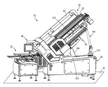
[0017] FIG. 1 is atop, front perspective view of one example of a food product
slicing apparatus, according to one aspect of the present disclosure;
[0018] FIG. 2 is a cross-sectional view of the food product slicing apparatus,
according to one aspect of the present disclosure;
[0019] FIG. 3 is a top view of the food product slicing apparatus illustrating
one
example of a first zone sensed by a first sensor, according to one aspect of
the present
disclosure;
[0020] FIG. 4 is a rear elevation view of the food product slicing apparatus
illustrating one example of a second zone sensed by a second sensor, according
to one
aspect of the present disclosure;
CA 02948158 2016-11-04
WO 2015/171858
PCT/US2015/029630
[0021] FIG. 5 is a cross-sectional view taken along a vertical plane extending
through
the food product slicing apparatus, according to one aspect of the present
disclosure;
[0022] FIG. 6 is a cross-sectional view taken along a vertical plane extending
through
the food product slicing apparatus, according to one aspect of the present
disclosure;
[0023] FIG. 7 is a cross-sectional view of a portion of the food product
slicing
apparatus showing the height adjustment assembly;
[0024] FIG. 7A is an alternate cross-sectional view of a portion of the food
product
slicing apparatus showing the height adjustment assembly;
[0025] FIG. 8 is an enlarged partial view of the food product slicing
apparatus
showing one example of a portion of an upper drive assembly with pressure
adjustment assemblies, according to one aspect of the present disclosure;
[0026] FIG. 9 is a cross-sectional view taken along a vertical plane extending
through
the food product slicing apparatus, according to one aspect of the present
disclosure;
[0027] FIG. 10 is side elevation view of a portion of the food product slicing
apparatus showing details of a tray;
[0028] FIG. 11 is an elevation view of the food product slicing apparatus with
an
example of a food product block loaded onto one example of a tray, according
to one
aspect of the present disclosure;
[0029] FIG. 12 is an elevation view of the food product slicing apparatus with
the tray
in an upward and forward position, according to one aspect of the present
disclosure;
[0030] FIG. 13 is an elevation view of the food product slicing apparatus with
the tray
moved further upward to a loading position, according to one aspect of the
present
disclosure;
6
CA 02948158 2016-11-04
WO 2015/171858
PCT/US2015/029630
[0031] FIG. 14 is an elevation view of the food product slicing apparatus with
one
example of grippers grasping a rear of the food product block, according to
one aspect
of the present disclosure;
[0032] FIG. 15 is an elevation view of the food product slicing apparatus with
one
example of a product gate moved to a downward position, according to one
aspect of
the present disclosure;
[0033] FIG. 16 is an elevation view of the food product slicing apparatus with
the
food product block driven forward toward a slicing station by one example of
an
upper drive assembly and one example of a lower drive assembly, according to
one
aspect of the present disclosure;
[0034] FIG. 17 is an elevation view of the food product slicing apparatus with
a
second food product block loaded onto the tray while slicing is being
performed on
the first food product block, according to one aspect of the present
disclosure;
[0035] FIG. 18 is an elevation view of the food product slicing apparatus with
slicing
operation of the first food product block near completion and the second food
product
block raised to an upward and rearward position, according to one aspect of
the
present disclosure;
[0036] FIG. 19 is an elevation view of the food product slicing apparatus with
slicing
operation of the first food product block completed and the grippers moving a
butt of
the first food product block rearward away from the slicing station, according
to one
aspect of the present disclosure; and
[0037] FIG. 20 is atop, front perspective view of a portion of the food
product slicing
apparatus with the butt of the first food product block dropped into one
example of a
7
CA 02948158 2016-11-04
WO 2015/171858
PCT/1JS2015/029630
butt or end cavity defined by the slicing apparatus, according to one aspect
of the
present disclosure.
8
CA 02948158 2016-11-04
WO 2015/171858
PCT/US2015/029630
DETAILED DESCRIPTION
[0038] While the disclosure may be susceptible to embodiment in different
forms,
there is shown in the drawings, and herein will be described in detail, a
specific
embodiment with the understanding that the present disclosure is to be
considered an
exemplification of the principles of the disclosure, and is not intended to
limit the
disclosure to that as illustrated and described herein. Therefore, unless
otherwise
noted, features disclosed herein may be combined together to form additional
combinations that were not otherwise shown for purposes of brevity. It will be
further
appreciated that in some embodiments, one or more elements illustrated by way
of
example in a drawing(s) may be eliminated and/or substituted with alternative
elements within the scope of the disclosure.
[0039] Food product slicing apparatuses and methods associated with the same
are
included in the present disclosure. The food product slicing apparatuses and
methods
have benefits over convention food product slicing apparatuses. For example,
the
food product slicing apparatuses and methods have one or more of improved food
product block control, increased safety without inhibiting cleaning of the
food product
slicing apparatus, a smaller footprint, and capability of accommodating food
product
blocks of various heights, among other benefits.
[0040] With reference to the figures, one example of a food product slicing
apparatus 20 is shown. The food product slicing apparatus 20 is used to slice
food
product blocks 22 into slices. The food product blocks 22 may be comprised of
a
wide variety of edible materials including, but not limited to meat, such as
beef,
9
chicken, fish, pork, etc., and cheese. In some examples, the food product
blocks 22 are
frozen.
[0041] The food product slicing apparatus 20 includes a base 24, an input and
slicing portion
26 pivotally mounted on the base 24, an output portion 28 mounted on the base
24 and
downstream of the input and slicing portion 26, and a control system 30
configured to control
operation of the food product slicing apparatus 20. The control system 30 may
be mounted on
the base 24. The base 24 supports the input and slicing portion 26, the output
portion 28, and
the control system 30 on a ground surface 32 and includes various mechanisms
and power
systems for powering the food product slicing apparatus 20. The input and
slicing portion 26
is configured to support and handle the food product blocks 22, to move the
food product
blocks 22 and to slice the food product blocks 22 into slices. The sliced food
product is
supported on the output portion 28 of the food product slicing apparatus 20 in
stacks and is
moved away from the input and slicing portion 26 by the output portion 28. The
control
system 30 includes all the necessary hardware and software to perform all of
the operations
and functions of the food product slicing apparatus 20.
[0042] With reference to FIGS. 1 and 2, the input and slicing portion 26
includes a frame 34,
a lower drive assembly 36 mounted on the frame 34, an upper drive assembly 38
mounted on
the frame 34 and which is movable relative to the frame 34 and relative to the
lower drive
assembly 36, a shear edge 40 mounted on the frame 34 and which is downstream
of the lower
drive assembly 36, a slicing station 42 mounted on the frame 34 and which is
downstream of
the shear edge 40, a removal member 44
CA 2948158 2018-03-13
CA 02948158 2016-11-04
WO 2015/171858
PCT/US2015/029630
mounted on the frame 34 upstream of the lower drive assembly 36, and a tray 46
mounted on the base 24 and upstream of the lower drive assembly 36.
[0043] The input and slicing portion 26 is pivotally mounted to the base 24
around
pivot 48. The tray 46 is pivotally mounted to the frame 34 around pivot 48,
such that
the tray 46 is pivotable relative to the lower and upper drive assemblies 36,
38, the
shear edge 40 and the slicing station 42. The lower and upper drive assemblies
36, 38
move food product blocks 22 from the tray 46 to the shear edge 40 and into the
slicing
station 42.
[0044] The frame 34 includes a pair of upstanding plates 50, 52, each of which
has
a least one aperture 54 therethrough. As a result, each plate 50, 52 includes
a lower
section 56, an upper section 58, a downstream section 60 and an upstream
section 62.
A pair of spaced apart support arms extend between the lower sections 56 of
the
plates 50, 52. A support rod 64, 65 extends upwardly from each support arm
between
the plates 50, 52 such that first and second support rods are defined, and an
upper end
of each support rod 64, 65 is affixed to the upper section 58 of the plate 50.
[0045] The lower drive assembly 36 is mounted on an upstream portion of the
plate
52. With reference to FIGS. 5 and 6, the illustrated example of the lower
drive
assembly 36 includes a plurality of endless drive belts 66, one for each food
product
block 22. Each endless drive belt 66 wraps around a plurality of wheels 68,
with at
least one of the wheels 68 being a drive wheel or being driven by a separate
drive
wheel. The wheels 68 are supported by shafts 70 which are cantilevered from
and
rotatably mounted to the upstream section of the plate 52. The endless drive
belts 66
define planar upper surfaces 72 upon which food product blocks 22 will
translate. A
11
motor (not shown) is provided to drive the shaft supporting the drive wheel. A
second end of
each shaft 70 is rotatably attached to a plate 74. The plate 74 is attached to
the upstream
section of the frame 34 by a belt tensioning assembly 76, the specifics of
which are not
described herein.
[0046] Each belt 66 includes a tactile surface 78 configured to engage bottom
surfaces of the
food product blocks 22. In the illustrated example, the tactile surface 78 of
each belt 66 is an
exterior surface of the belt 66. The tactile surfaces 78 of the belts 66 may
have a variety of
configurations to ensure adequate engagement, grip, friction, etc., between
the belts 66 and
the food product blocks 22. In one example, the tactile surface 78 may include
a corrugation
shape, thereby providing alternating projections and recesses. In another
example, the tactile
surface 78 may include projections extending therefrom having any shape.
[0047] A downstream end of the upper drive assembly 38 is mounted on the
support rods 64,
65 of the frame 34 and is movable relative thereto. The upper drive assembly
38 extends from
the downstream end of the frame 34 to the upstream end of the frame 34. As
such, the
upstream end of the upper drive assembly 38 is positioned above the lower
drive assembly
36.
[0048] As shown in FIGS. 5, 6 and 8, the upper drive assembly 38 includes a
housing 80, a
plurality of belt and wheel assemblies 82 mounted to the housing 80, and
pressure adjustment
assemblies 84. The pressure adjustment assemblies 84 are attached to the
upstream ends of
the belt and wheel assemblies 82 to apply varying pressures to top surfaces of
the food
product blocks 22 as food product blocks 22 engage with the upper drive
assembly 38. A
height adjustment assembly 86 is
12
CA 2948158 2018-03-13
mounted within the housing 80 to adjust the height of the upper drive assembly
38 relative to
the frame 34 and relative to the lower drive assembly 36.
[0049] The housing 80 has a pair of upright side walls 87, 88, a bottom wall
90 and a top wall
92. The support rods 64, 65 extend through the bottom and top walls 90, 92 and
the housing
80 is slidable on the support rods 64, 65 as discussed herein.
[0050] The distance the upper drive assembly 38 is spaced from the lower drive
assembly 36
is adjustable by the height adjustment assembly 86 to correspond to a height
of food product
blocks 22 that will be sliced by the food product slicing apparatus 20. Food
product blocks 22
come in a variety of heights and such heights may vary depending on a variety
of factors such
as, for example, type of food product, type of machine used to form the food
product blocks
22, etc. The height adjustment assembly 86 includes an actuator 94, a first
pivot member 98,
a first pivot shaft 100, a first plurality of slide members 102, a first
connecting frame 104, a
second pivot member 106, a second pivot shaft 108, a second plurality of slide
members 110,
a second connecting frame 112, and a connecting bar 114, and a cam slot 116,
117 which is
formed on each of the rods 64, 65.
[0051] The actuator 94 is mounted on the side wall 88 of the housing 80. A
piston of the
actuator 94 is extendable and retractable. A rocker member 96 of the actuator
94 is attached
to the end of the piston and is fixedly mounted on the first pivot shaft 100
such that the rocker
member 96 does not pivot relative to the first pivot shaft 100
[0052] The first pivot shaft 100 extends between the side walls 87, 88 of the
housing 80 and
is rotatably attached thereto. The first pivot shaft 100 is attached to the
housing 80 proximate
to the upstream end of the housing 80. The first pivot
13
CA 2948158 2018-03-13
member 98 is fixedly mounted on the first pivot shaft 100 such that the first
pivot member 98
does not pivot relative to the first pivot shaft 100. The lower end of the
first pivot member 98
is attached to the rod 64. The rod 64 has the cam slot 116 formed therein and
the lower end of
the first pivot member 98 has a pin 119 extending therefrom which seats in the
cam slot 116.
Upon rotation of the first pivot member 98 relative to the housing 80, the pin
119 slides along
the cam slot 1 16. The motion of the pin 119 is restrained by the length of
the cam slot 116.
[0053] The second pivot shaft 108 extends between the side walls 87, 88 of the
housing 80
and is rotatably attached thereto. The second pivot member 106 is fixedly
mounted proximate
to the downstream end of the housing 80 on the second pivot shaft 108 such
that the second
pivot member 106 does not pivot relative to the second pivot shaft 108. The
lower end of the
second pivot member 106 is attached to the rod 65. The rod 65 has the cam slot
117 formed
therein and the lower end of the second pivot member 106 has a pin 121
extending therefrom
which seats in the cam slot 117. Upon rotation of the second pivot member 106
relative to the
housing 80, the pin 121 slides along the cam slot 117. The motion of the pin
121 is restrained
by the length of the cam slot 17.
[0054] The cam slots 116, 117 are horizontal when the bottom wall 90 of the
housing 80 is
parallel to the ground surface 32.
[0055] The connecting bar 114 extends between upper ends of the first and
second pivot
members 98, 106 such that the rocker member 96, the pivot members 98, 106 and
the pivot
shafts 100, 108 will move in unison relative to the housing 80 and the rods
64, 65.
14
CA 2948158 2018-03-13
[0056] The first slide members 102 form rings around the support rod 64 and
are slidable
relative to the support rod 64. The connecting frame 104 is fixedly attached
to each slide
member 102 on an opposite side of the support rod 64 to that where the first
pivot member 98
is attached. The connecting frame 104 is affixed to the side walls 87, 88 of
the housing 80.
The second slide members 110 form rings around the support rod 65 and are
slidable relative
to the support rod 65. The connecting frame 112 is fixedly attached to each
slide member 110
on an opposite side of the support rod 65 to that where the second pivot
member 106 is
attached. The connecting frame 112 is affixed to the side walls 87, 88 of the
housing 80.
[0057] With reference to FIGS. 2, 6, 9, the illustrated example of the belt
and wheel
assemblies 82 includes a plurality of endless drive belts 118, one for each
food product block
22. Each endless drive belt 118 wraps around a plurality of wheels 120, with
at least one of
the wheels 120 being a drive wheel or being driven by a separate drive wheel.
The wheels
120 are supported by shafts 122, some of which extend from the side wall 88 of
the housing
80 to a plate 124 and other of which extend between plate 124 and an opposite
plate (not
shown) or are provided as part of the pressure adjustment assemblies 84. The
endless drive
belts 118 define planar lower surfaces 126 upon which food product blocks 22
will translate
(the drive belts 118 are planar subject to use of the pressure adjustment
assemblies 84 as
described herein). A motor (not shown) is provided to drive the shaft
supporting the drive
wheel. A belt tensioning assembly 128, the specifics of which are not
described herein, is
provided at the upstream section of each belt and wheel assembly 82.
CA 2948158 2018-03-13
CA 02948158 2016-11-04
WO 2015/171858
PCT/US2015/029630
[0058] The drive belts 118 include a tactile surface 130 configured to engage
top
surfaces of the food product blocks 22. In the illustrated example, the
tactile surface
130 of each belt 118 is an exterior surface of the belt 118. The tactile
surfaces 130
may have a variety of configurations to ensure adequate engagement, grip,
friction,
etc., between the belts 118 and the food product blocks 22. In one example,
the tactile
surface 130 may include a corrugation shape, thereby providing alternating
projections and recesses. In another example, the tactile surface 130 may
include
projections extending therefrom having any shape.
[0059] With additional reference to FIG. 11, each belt 118 has a gripper 132
coupled thereto. Such grippers 132 are known in the art. The grippers 132 move
with
the belts 118. The grippers 132 have an adjustment mechanism for moving the
grippers 132 relative to the belts 118.
[0060] The pressure adjustment assemblies 84 are attached at the upstream end
of
the end of the belt and wheel assemblies 82. Referring now to FIGS. 5 and 8,
the
pressure adjustment assemblies 84 are used to apply varying pressures to top
surfaces
of the food product blocks 22 as they engage with the upper drive assembly 38.
Each
pressure adjustment assembly 84 includes the fonvardmost wheels 120 of the
individual belt and wheel assemblies 82 and are capable of moving the
forwardmost
wheels 120 toward or away from the lower drive assembly 36.
[0061] A pivot shaft 134 extends between the front ends of the plates (124 and
the
other plate is not shown) and is used to mount the pressure adjustment
assemblies 84
thereon. In addition, a mounting bar 136 extends between the front ends of the
plates
16
124 and the other plate is not shown) at a position which is above and
rearwardly of the pivot
shaft 134.
[0062] Each pressure adjustment assembly 84 is identically formed and only one
of the
pressure adjustment assemblies 84 is described for ease in description. The
pressure
adjustment assembly 84 includes a pair of mounting plates 138 (only one of
which is shown)
which are mounted on the pivot shaft 134 at a rearward end of each mounting
plate 138. The
forwardmost wheels 120 are mounted between the mounting plates 138. The
pressure
adjustment assembly 84 further includes a pair of adjusting plates 140 (only
one of which is
shown) which have a shaft 142 extending therebetween. Each adjusting plate 140
is attached
to the pivot shaft 134 at its lower, rearward end and to the shaft 142 at its
upper, rearward
end. The mounting plates 138 and adjusting plates 140 are affixed together by
a shaft 143.
Alternatively, the respective mounting plates 138 and respective adjusting
plates 140 can be
formed as a single component. The pressure adjustment assembly 84 additionally
includes a
drive member 144. The drive member 144 is mounted on the mounting bar 136 and
engages
with the shaft 142. The drive member 144 may be a wide variety of types of
drive members
including, but not limited to, pneumatic, hydraulic, screw drive, electronic,
etc., and all of
such possibilities are intended to be within the spirit and scope of the
present disclosure.
[0063] The removal member 44 is mounted on the lower section 56 of the plate
52 proximate
to the upstream end of the lower drive assembly 36. The removal member 44
translates in a
direction generally perpendicular to feed paths 146 of the food product blocks
22. The
removal member 44 may be driven in a variety of
17
CA 2948158 2018-03-13
CA 02948158 2016-11-04
WO 2015/171858
PCT/US2015/029630
manners including, but not limited to, pneumatically, hydraulically, screw
drive, or
any other appropriate manner.
[0064] The shear edge 40 is conventional and defines a plurality of apertures
148,
one for each food product block 22. The shear edge 40 is attached to the
upstream
portion of the frame 34, and is upstream of the lower and upper drive
assemblies 36,
38.
[0065] The belts 66 of the lower drive assembly 36 linearly align with the
belts 118
of the upper drive assembly 38. The belts 66, 118 linearly align with the
apertures
148 in the shear edge 40.
[0066] The slicing station 42 is conventional and the specifics are not
described
herein. The slicing station 42 includes a blade which moves upwardly and
downwardly relative to the shear edge 40 to slice the food product blocks 22
into
individual slices.
[0067] A food product block sensor 150 is mounted on the downstream section of
the frame 34 and aligns with the lower drive assembly 36. The food product
block
sensor 150 is in communication with the control system 30.
[0068] The tray 46 is pivotally mounted to the frame 34 and is pivotable
relative to
the lower and upper drive assemblies 36, 38, the shear edge 40 and the slicing
station
42. The tray 46 is configured to support a plurality of food product blocks
22.
[0069] Referring now to FIG. 9, the tray 46 includes a housing 151 including a
pair
of arms 152 pivotally mounted on the frame 34 at pivot 48, a base 154 attached
to the
arms 152, a first drive mechanism 155 for translating the base 154 relative to
the
arms, a butt receiving wall 156 provided on the base 154, a product gate 158
mounted
18
CA 02948158 2016-11-04
WO 2015/171858
PCT[1JS2015/029630
on the base 154, a support member 160 mounted on the base 154 by a second
drive
mechanism 162 for adjusting the position of the support member 160 relative to
the
base 154, and a third drive mechanism 164 for pivoting the tray 46 relative to
the base
154 and to the frame 34. The product gate 158 is upstream of the support
member
160, and the butt receiving wall 156 is upstream of the product gate 158. The
pivot
48 is upstream of the butt receiving wall 156.
[0070] The arms 152 are elongated and extend from the pivot 48. The arms 152
can
pivot relative to the frame 34 at pivot 48.
[0071] The base 154 is attached between the arms 152 by the first drive
mechanism
155, which are formed by drive members. Each drive member has a first end
attached
to a respective arm 152 and a second end attached to the base 154. The drive
members may be a wide variety of types of drive members including, but not
limited
to, pneumatic, hydraulic, screw drive, electronic, etc., and all of such
possibilities are
intended to be within the spirit and scope of the present disclosure. When the
drive
members are activated, the base 154 translates along the length of the arms
152.
[0072] The butt receiving wall 156 is mounted at the upstream end of the base
154.
The butt receiving wall 156 extends upwardly from a top surface of the base
154, and
may be generally U-shaped as shown. The inner surface of the butt receiving
wall
156 defines a cavity 157 and may have corrugations thereon.
[0073] The product gate 158 is formed of an upright housing 166 having a
plurality
of rods 168 mounted therein. Each rod 168 has a rotatable roller 170 mounted
at is
upper end. The rods 168 can be extended upwardly from the housing 166 and
retracted back into the housing 166, such that the rollers 170 can be moved
upwardly
19
CA 02948158 2016-11-04
WO 2015/171858
PCT/US2015/029630
and then downwardly relative to the base 154. The rods 168 are driven by a
drive
member and may be a wide variety of types of drive member including, but not
limited to, pneumatic, hydraulic, screw drive, electronic, etc., and all of
such
possibilities are intended to be within the spirit and scope of the present
disclosure.
100741 The support member 160 has a planar top surface 172 which engages
a
bottom of the food product blocks 22 to support the food product blocks 22
from
below.
[0075] The second drive mechanism 162 is disposed between the base 154 and the
support member 160 to move the support member 160 and the food product blocks
22
away from the base 154. In one example, the drive mechanism 162 moves the
support member 160 and food product blocks 22 in a direction perpendicular to
a
longitudinal extent of the lower base 154. In one example, the drive mechanism
162
is a scissor drive mechanism.
[0076] The third drive mechanism 164 extends between the base 24 and the
bottom
of the base 154. The third drive mechanism 164 may be a wide variety of types
of
drive members including, but not limited to, pneumatic, hydraulic, screw
drive,
electronic, etc., and all of such possibilities are intended to be within the
spirit and
scope of the present disclosure.
[0077] Referring now to FIGS. 1 and 3, the output portion 28 of the food
product
slicing apparatus 20 is illustrated and will be described in more detail. The
output
portion 28 includes a plurality of conveyors 174, one for each stack of food
products
sliced from the corresponding food product blocks 22. In the illustrated
example, the
output portion 28 includes three conveyors 174 to correspond to three food
product
blocks 22. In other examples, the output portion 28 may include any number of
food product
blocks 22 and a corresponding number of conveyors 174 to accommodate the
sliced food
stacks resulting from the food product blocks 22. The conveyors 174 are all
linear and
parallel to each other to convey the sliced food product stacks in a linear
path 176 away from
the slicing station 42. The conveyors 174 linearly align with the belts 66,
118 of the lower
and upper drive assemblies 36, 38.
[0078] The output portion 28 also includes a plurality of weighing stations
180 formed by
weighing scales, one associated with each conveyor 174. The weighing scales
weigh each
stack of sliced food product to ensure an appropriate amount of food product
in each stack.
The weighing scales are oriented under the conveyors 174 and are positioned
close together.
[0079] The linear and parallel output conveyors 174, along with the closely
positioned
weighing scales, decrease the overall footprint occupied by the conveyors 174
and the output
portion 28 as a whole. Additionally, the linear and parallel output conveyors
174 along with
the closely weighing scales provide a shortest possible travel path for the
sliced food stacks
from the slicing station 42 to various downstream points such as, for example,
the weighing
station 180 (i.e., the location of the weighing scales), the packaging station
182 (i.e., the
location where the sliced food product stacks are placed in packaging), etc.
Thus, the sliced
food product stacks move along linear paths 176 from the slicing station 42 to
the weighing
station 180, and move along linear paths 176 from the slicing station 42 to
the packaging
station 182.
21
CA 2948158 2018-03-13
[0080] Now that the specifics of the components of the food product slicing
apparatus 20
have been described, the operation of the food product slicing apparatus 20 is
described.
[0081] Initially, the food product slicing apparatus 20 is in a load position
as shown in FIG.
11 to facilitate loading of food product blocks 22 onto the tray 46. The tray
46 is in a lowered
and rearward position. The butt receiving wall 156 is provided upstream of the
tray 46
between the tray 46 and the lower drive assembly 36. The grippers 132 are
proximate to the
upstream end of the upper drive assembly 38. FIG. 11 shows a food product
block 22 loaded
onto the support member 160 of the tray 46. The lower surface of the food
product block 22
seats on the upper surface of the support member 160 and the front end of the
food product
block 22 engages against the housing of the product gate 158.
[0082] Once the food product block 22 is loaded onto the support member 160,
the drive
mechanism 164 is engaged to rotate the tray 46 upward around pivot 48, as
shown in FIG. 12,
such that the planar top surface 172 of the support member 160 is parallel to
the planar upper
surfaces 72 of the lower drive assembly 36 and parallel to the planar lower
surfaces 126 of
the upper drive assembly 38. Next, the drive mechanism 155 is engaged to
translate the tray
46 forward toward the lower drive assembly 36, as shown in FIG. 12. The
support member
160 translates relative to the base 154 in a direction parallel to a
longitudinal extent of the
tray 46. In this position, the butt receiving wall 156 is positioned
underneath the lower drive
assembly 36. The product gate 158 remains positioned in front of the food
product blocks 22.
The support member 160 supports the food product blocks 22 from below and the
product
22
CA 2948158 2018-03-13
CA 02948158 2016-11-04
WO 2015/171858
PCT[1JS2015/029630
gate 158 supports the food product blocks 22 from the front. The food product
sensor
150 determines the length of the food product blocks 22 and communicates this
information to the control system 30.
10083] As shown in FIG. 13, the drive mechanism 162 is engaged to move the
support member 160 upwardly relative to the base 154 and to engage the
portions of
the planar surfaces 126 of the upper drive assembly 38 that are upstream of
the lower
drive assembly 36. The product gate 158 is also activated to extend the rods
168
upwardly such that the food product blocks 22 engage against the rods 168. In
this
position, the rods 168 of the product gate 158 remain positioned in front of
the
support member 160. The grippers 132 are activated to engage and grasp the
rear
ends of the food product blocks 22 as shown in FIG. 14. The support member 160
supports the food product blocks 22 from below, the product gate 158 supports
the
food product blocks 22 from the front, and the upper drive assembly 38 engages
the
upper surfaces of the food product blocks 22, thereby limiting forward
movement of
the food product blocks 22 in a forward direction and preventing the food
product
blocks 22 from moving toward the slicing station 42. In the illustrated
example, the
belts 118 engage the food product blocks 22 along an entire length of the
blocks 22.
Engaging the blocks 22 along an entire length thereof provides a significant
engagement area between the belts 118 and the food product blocks 22, thereby
improving control of the food product blocks 22 during various operations of
the food
product slicing apparatus 20. In other examples, the belts 118 may engage the
food
product blocks 22 along significant portions of the lengths of the food
product blocks
23
CA 02948158 2016-11-04
WO 2015/171858
PCT[1JS2015/029630
22. In further examples, the belts 118 may engage the food product blocks 22
along a
majority of the lengths of the food product blocks 22.
[0084] Referring now to FIG. 15, the rods 168 and rollers 170 of the product
gate
158 are lowered out from in front of the food product blocks 22 until the tops
of the
rollers 170 are aligned with the upper surface of the support member 160. The
food
product blocks 22 remain in position after lowering of the product gate 158
due to the
grippers 132 grasping a rear of the food product blocks 22 and engagement of
the
belts 118 with the top surface of the food product blocks 22. A food product
block 22
may have a substantial weight depending on a size of the food product block 22
and
the type of food product. In some cases, grippers 132 may disengage or fail to
grip a
rear end of the food product block 22. Without engagement of the belt 118 with
the
top surface of the food product block 22, the food product block 22 would move
uncontrollably along the feed path 146 toward the slicing station 42 if the
grippers
132 fail. Uncontrolled falling or movement of the food product block 22 along
the
feed path 146 toward the slicing station 42 may damage components of the food
product slicing apparatus 20 or may cause misalignment of the food product
block 22,
thereby causing operation downtime to repair and/or reposition/realign the
food
product block 22. Thus, engagement of the food product blocks 22 with the
belts 118
of the upper drive assembly 38 provides continuous control of the food product
blocks
22.
[0085] Referring now to FIG. 16, the upper drive assembly 38 is engaged to
move
the food product blocks 22 along their feed paths 146 toward and along the
lower
drive assembly 36. The food product blocks 22 roll over the rollers 170 of the
24
product gate 158 as they translate onto the lower drive assembly 36. The upper
drive
assembly 38 drives the food product blocks 22 into engagement with the lower
drive
assembly 36. In one example, the belts 66, 118 of the lower and upper drive
assemblies 36,
38 are driven at the same rate. In another example, the belts 66, 118 of the
lower and upper
drive assemblies 36, 38 may be driven at different rates. In further examples,
sets of upper
and lower belts 66, 118 associated with individual food product blocks 22 may
be driven
independent of other sets of upper and lower belts 66, 118 to drive food
product blocks 22
along their feed paths 146 at different rates. Upon engagement of the food
product blocks 22
with the lower belts 66, the food product blocks 22 are driven along their
respective feed
paths 146 by both the lower and upper drive assemblies 36, 38.
[0086] The pressure adjustment assemblies 84 may be activated to apply varying
pressures to
top surfaces of the food product blocks 22 near the front ends of the food
product blocks 22
to inhibit movement of the front ends of the food product blocks 22 prior to
inserting into the
shear edge 40. The pressure adjustment assemblies 84 assist with ensuring the
food product
blocks 22 are properly aligned with the apertures 148 in the shear edge 40 to
facilitate
insertion of the blocks 22 into the apertures 148 without interference with
edges of the
apertures 148, other portions of the shear edge 40 or other portions of the
food product slicing
apparatus 20. During activation of the pressure adjustment assemblies 84 which
are best
shown in FIG. 8, the drive members 144 are activated which causes the drive
members 144 to
bear against the shafts 142. This causes the plates 138, 140 and associated
wheels 120 to
pivot around pivot shaft 134, which moves wheels downwardly toward the lower
drive
assembly 36. In one
CA 2948158 2018-03-13
example, the pressure adjustment assemblies 84 all apply a similar pressure to
top surfaces of
the food product blocks 22. In other examples, the pressure adjustment
assemblies 84 may be
individually controlled to apply different pressures to different food product
blocks 22.
Additionally, heights of the pressure adjustment assemblies 84 may be adjusted
by using the
drive members 144 to pivot the wheels 120 to accommodate various heights of
food product
blocks 22. In one example, the pressure adjustment assemblies 84 all have the
same height. In
other examples, the pressure adjustment assemblies 84 may be individually
controlled to have
different heights relative to each other to accommodate food product blocks 22
having
different heights. In one example, the pressure adjustment assemblies 84 may
be moved to
accommodate a height difference of the food product blocks 22 of about 1.5
inches. In
another example, the pressure adjustment assemblies 84 may be moved to
accommodate a
height difference of the food product blocks 22 of more than 1.5 inches.
10087] Referring now to FIG. 17, with the food product blocks 22 sufficiently
advanced
along their feed paths 146 into the slicing station 42 (not shown in FIG. 17),
the tray 46 may
return back to its initial position as shown in FIG. 11. The support member
160 moves toward
the base 154 by activating the drive mechanism 162, then the tray 46
translates away from the
slicing station 42 by activating the drive mechanism 155 such that the butt
receiving wall 156
is proximate to the upstream end of the lower drive assembly 36 and aligns
with the removal
member 44. The tray 46 then rotates downward toward the base 24 by using drive
mechanism
164. Another set of food product blocks 22 may then be loaded onto the tray
46.
26
CA 2948158 2018-03-13
[0088] With reference to FIG. 18, the lower and upper drive assemblies 36, 38
continue to
drive the food product blocks 22 along their feed paths 146 into the slicing
station 42. Upon
loading of new food product blocks 22, the tray 46 rotates upward using drive
mechanism
164, but is positioned below the feed paths 146 and displaced below the upper
drive assembly
38. This spacing 186 of the new food product blocks 22 and the upper drive
assembly 38
allows retraction of the grippers 132 to a rear of the new food product blocks
22.
[0089] Referring now to FIG. 19, the food product slicing apparatus 20 does
not facilitate
slicing of the entire food product blocks 22. The remaining, unsliced portion
of a food
product block 22 is referred to as a "butt'' 188. Upon completion of the
slicing operation of
the food product blocks 22, the lower and upper drive assemblies 36, 38
reverse driving
directions and the butts 188 of the food product blocks 22 move rearward away
from the
slicing station 42 while still be grasped by the grippers 132. As the butts
188 and the grippers
132 pass over the butt receiving wall 156, the grippers 132 release the butts
188 and the butts
188 drop into the cavity 157 formed by the butt receiving wall 156. The
removal member 44
is activated to move butts 188 out of the butt receiving wall 156. In the
illustrated example,
the removal member 44 pushes the butts 188 out of the cavity 157 to a side of
the food
product slicing apparatus 20. The food product slicing apparatus 20 includes a
side chute 200
through which the butts 188 pass out of the cavity 157 of the butt receiving
wall 156 and to a
side of the food product slicing apparatus 20. During operation, the removal
member 44
moves outward to push the butts 188 out of the cavity 157 of the butt
receiving wall 156 to a
side of the food product slicing apparatus 20 and then retracts
27
CA 2948158 2018-03-13
to its inward at rest position. In some examples, the removal member 44 may
pull the butts
188 out of the cavity 157 of the butt receiving wall 156 . In other examples,
the removal
member 44 may rotate to cause the butts 188 to move out of the cavity 157 of
the butt
receiving wall 156. In further examples, the removal member 44 may move in a
variety of
directions relative to the feed paths 146 and the food product slicing
apparatus 20 such as, for
example, parallel to the feed paths 146, transverse to the feed paths 146, in
a direction
between parallel and perpendicular to the feed paths 146, or any other
direction. It should be
understood that the removal member 44 may be configured in a wide variety of
manners and
move in a variety of different directions, and all of such possibilities are
intended to be within
the spirit and scope of the present disclosure.
[0090] Thereafter, the food product slicing apparatus 20 moves to the
condition shown in
FIG. 11 as described herein and the operation is restarted.
[0091] With particular reference to FIGS. 7 and 7A, the height adjustment
assembly 86 is
used adjust the height of the upper drive assembly 38 relative to the lower
drive assembly 36
to accommodate food product blocks 22 of different heights. The height
adjustment assembly
86 is controlled by the control system 30.
[0092] In use, the actuator 94 is extended which causes the rocker member 96
and the pivot
members 98, 106 to pivot relative to the side walls 87, 88 of the housing 80.
When the pivot
members 98, 106 pivot, the pins 119, 121 slide along the cam slots 116, 117.
Since the pivot
shafts 100, 108 are attached to the side walls 87, 88, when the pivot members
98, 106 pivot,
this causes the housing 80 to translate upwardly. Since the connecting frames
104, 112, are
attached to the side members 102, 110, the
28
CA 2948158 2018-03-13
slide members 102, 1 10 slide upwardly along the rods 64, 65. Since the upper
drive
assembly 38 is attached to the housing 80, the movement increases the spacing
between the
lower and upper drive assemblies 36, 38. To reduce the spacing between the
lower and upper
drive assemblies 36, 38, the actuator 94 is retracted which causes the rocker
member 96 and
the pivot members 98, 106 to pivot relative to the side walls 87, 88, and the
pins 119, 121 to
slide the opposite direction in the cam slots 116, 117. The housing 80
translates downwardly
and the slide members 102, 110 slide downwardly along the rods 64, 65.
100931 The housing 80 and attached upper drive assembly 38 move to provide a
sufficient
distance or space 192 between the upper and lower belts 66, 118 to allow the
food product
blocks 22 to move along their feed paths 146 between the upper and lower belts
66, 118. The
position to which the upper drive assembly 38 moves also ensures contact of
the upper belts 1
18 with top surfaces of the food product blocks 22. The food product slicing
apparatus 20 has
significant flexibility to accommodate food product blocks 22 of varying
heights. This
flexibility is provided by the combination of the movable upper drive assembly
38 and the
movable pressure adjustment assemblies 84 at the front of the upper drive
assembly 38.
[0094] A drive mechanism 184 is mounted between the base 24 and the input and
slicing
portion 26 to lift the entire input and slicing portion 26 relative to the
base 24 for cleaning
purposes. The mechanism 184 may include a wide variety of types of drive
members
including, but not limited to, pneumatic, hydraulic, screw drive, electronic,
etc., and all of
such possibilities are intended to be within the spirit and scope of the
present disclosure. This
enables the food product slicing apparatus 20 to
29
CA 2948158 2018-03-13
CA 02948158 2016-11-04
WO 2015/171858
PCT[1JS2015/029630
be oriented at an angle a relative to the base 24 and the ground surface 32
upon which
the food product slicing apparatus 20 is supported. The input and slicing
portion 26
may be oriented at a variety of different angles relative to the base 24 and
the ground
surface 32, and all of such possibilities are intended to be within the spirit
and scope
of the present disclosure.
[0095] With reference to FIGS. 1 and 3, the food product slicing apparatus 20
includes two safety sensors 210, 212 for sensing various areas around the food
product slicing apparatus 20 to inhibit users or other individuals from
entering
dangerous areas of the food product slicing apparatus 20. The sensors 210, 212
are in
communication with the control system 30. The two sensors 210, 212 operate on
two
different planes. The first sensor 210 is coupled to the base 24 and senses a
first area
214 in a plane generally parallel to a top surface 218 of the base 24 (see
FIGS. 3 and
4). The second sensor 212 is coupled to the input and slicing portion 26 and
senses a
second area 216 in a generally vertical plane perpendicular to the first
sensed area 214
and the ground surface 32 upon which the food product slicing apparatus 20 is
supported. The first and second areas 214, 216 are defined to cover areas
around the
food product slicing apparatus 20 in which a user or other individual may be
injured
by the food product slicing apparatus 20 during operation. If one or more of
the first
or second areas 214, 216 is breached, operation of the food product slicing
apparatus
20 will cease until the food product slicing apparatus 20 is reset and the
first and
second areas 214, 216 are clear. It should be understood that the sensed areas
and
planes may have different shapes, sizes, configurations, and orientations than
those
CA 02948158 2016-11-04
WO 2015/171858
PCT/US2015/029630
illustrated and described herein, and all of such possibilities are intended
to be within
the spirit and scope of the present disclosure.
[0096] While a particular embodiment is illustrated in and described with
respect to
the drawings, it is envisioned that those skilled in the art may devise
various
modifications without departing from the spirit and scope of the appended
claims. It
will therefore be appreciated that the scope of the disclosure and the
appended claims
is not limited to the specific embodiment illustrated in and discussed with
respect to
the drawings and that modifications and other embodiments are intended to be
included within the scope of the disclosure and appended drawings. Moreover,
although the foregoing descriptions and the associated drawings describe
example
embodiments in the context of certain example combinations of elements and/or
functions, it should be appreciated that different combinations of elements
and/or
functions may be provided by alternative embodiments without departing from
the
scope of the disclosure and the appended claims.
31