Note: Descriptions are shown in the official language in which they were submitted.
CA 02948189 2016-11-04
WO 2015/187421 PCT/US2015/032605
-I-
TWO Oil. CH,WBER COUNTERWEIGHT
BACKGROUND
[0001] The present disclosure generally relates to rock crushing
equipment. .More
specifically, the present disclosure relates to a cone crusher including a
connterweight that
rotates along with an .eccentric and includes two separate oil chambers.
[0002] Rock crushing systems, such as those referred to as cone crushers,
generally break
apart rock, stone or other material in a crushing gap between a stationary
element and a moving
element. For example, a conical rock crusher is comprised of a head assembly
including a
crushing head .that gyrates about a vertical axis within a stationary bowl
indirectly attached to a
main frame of the rock crusher. The crushing head is assembled surrounding an
eccentric that
rotates about a fixed main shaft to impart the gyrational motion of the
crushing head which
crushes rock, stone or other material in a crushing gap between the crushing
head and the bowl.
The eccentric can be driven by a variety of power drives, such as an attached
gear, driven by a.
pinion and countershaft assembly, and a number of mechanical power sources,
such as electrical
motors or combustion engines.
[0003] The exterior of the conical crushing head is covered with a
protective or wear-
resistant mantle that engages the material that is being crushed, such as
rock, stone, or other
material. The bowl, which is indirectly mechanically fixed to the main frame,
is fitted with a
bowl liner. The bowl liner and bowl are stationary and spaced .from the
crushing head.. The
bowl liner provides an opposing, surface from the mantle for crushing, the
material. The material
is crushed in the crushing gap between the mantle and the bowl liner.
[0004] The gyrational motion of the crushing head with respect to the
stationary bowl
crushes rock, stone or other material within the crushing gap. Generally, the
rock, stone or other
material is fed onto a feed plate that directs the material toward the
crushing gap where the
material is crushed as it travels through the crushing gap. The crushed
material exits the
crushing chamber through the bottom of the crushing gap. The size of the
crushing gap
determines the maximum size of the crushed material that exits the crushing
gap.
[0005] In currently available cone crushers, a supply of lubricating oil
is directed to the
bushing located between the eccentric and the stationary main shaft and to the
bushing located
between the head assembly and the eccentric. The lubricating oil drains
through holes that are
CA 02948189 2016-11-04
WO 2015/187421 PCT/US2015/032605
- -
formed in the crushing hea.d and. eventually drops onto a. moving
counterweight. that is attached.
to the eccentric. As the rotational speed of the eccentric and the attached
counterweight
increases, oil is flung around the interior of the counterweight. Some of this
oil may escape out
through seals within the. cone crusher., which can result in the need for
replacing the lost oil.
[0006] The counterweight has two main functions in a cone crusher. First,
the
counterweight functions to balance the centrifugal forces of the head and
eccentric. Second, the
counterweight functions to create a path and seal oil between the gyrating
head and the stationary
main frame.
[0007] Often, positive pressure air is added to the internals of the cone
crusher to keep
dust from being pulled in through the seals. The positive air pressure can
amplify oil leakage in
current designs.
SUMMARY
[0008] The present disclosure relates to a counterweight for use in rock
crushing
equipment, such as a cone crusher. The counterweight includes two separate oil
chambers that
receive lubricating oil and direct the lubricating oil to an oil sump.
[0009] The counterweight of the present disclosure is for use with a cone
crusher that
includes a stationary bowl. A head assembly is positioned for movement within
the stationary
bowl to create a crushing gap between the stationary bowl and the head
assembly. The head
assembly includes a crushing head and mantle. The head assembly is received
around an
eccentric that is in turn rotatable about a stationary main shaft. The
configuration of the
eccentric causes the head assembly to gyrate within the stationary bowl upon
rotation of the
eccentric around the main shaft.
[0010] The counterweight constructed in accordance with the present
disclosure is
mounted to the eccentric and rotates with the eccentric. The counterweight
includes both an.
inner oil chamber and an outer oil chamber that each receive lubricating oil
and direct the
lubricating oil to a main oil sump of the cone crusher.
[0011] The eccentric includes a generally horizontal .floor that extends
from an inner
edge to an outer edge. A vertical separating wall extends .from the generally
horizontal floor and
is positioned at a location between the inner edge and the outer edge. The
vertical separating.
wall separates the inner oil chamber from the outer oil chamber.
CA 02948189 2016-11-04
WO 2015/187421 PCT/US2015/032605
- 3 -
[0012] A splash shield is mounted to the vertical separating wall and is
positioned to
overhang at .least a portion of the horizontal floor that is radially inward
from the vertical
separating wall. The splash shield further- separates the inner oil chamber
from the outer oil
chamber and defines an upper barrier for the inner oil chamber as well as a
lower barrier for the
outer oil chamber. In one embodiment of the disclosure, the .splash shield is
formed from a
plurality of shield plates that are each separately attached to the vertical
separating mill. The.
splash shield extends around the entire internal circumference of the
counterweight such that the
inner oil chamber also extends around the entire circumference of the
counterweight. The inner
oil chamber includes a plurality of spaced inner chamber drain holes that
allow oil to pass
through the floor of the counterweight.
[0013] The counterweight further includes an outer oil chamber that is
formed between
the vertical separating wall and an inclined inner wall of the counterweight.
The outer oil
chamber is spaced radially outward relative to the inner oil chamber and
separated from the inner
oil chamber by the vertical separating wall and the splash shield. The outer
oil chamber includes
a plurality of spaced outer chamber drain holes that allow oil to pass from
the outer oil chamber
through the counterweight floor and into the main sump of the cone crusher.
The outer chamber
also extends the circumference of the counterweight.
[0014] An outer end of the splash shield is attached to the separating
wall while an inner
end of the splash shield is closely spaced to an outer surface of the crushing
head. The small gap
created between the crushing head and the inner end of the splash shield
entraps most of the
drained lubricating oil within the inner oil chamber. The portion of oil or
oil mist that escapes.
through the gap between the splash shield and the crushing head is directed
into contact with a
head skirt. The head skirt is positioned to direct oil or the oil mist away
from the seal between
the counterweight and the crushing head such that the oil can be drained from
the counterweight
through the drain holes formed in the outer oil chamber.
[0015] The combination of the inner and outer oil chambers collects and
drains the
lubricating oil and prevents the lubricating oil from passing through the seal
assemblies between.
the counterweight and the crushing head. The splash shield that forms a part
of the inner oil
chamber quickly directs most of the oil into the sump and greatly reduces the
amount of oil that
contacts the inclined inner wall of the counterweight, thereby reducing the
amount of oil loss.
CA 02948189 2016-11-04
WO 2015/187421 PCT/US2015/032605
- 4 -
The splash shield is constructed of multiple shield plates such that the
splash shield can be easily
assembled within the interior of the counterweight.
[0016] Various other features, objects and advantages of the invention
will be made
apparent from the following, description taken together with the drawings.
BRIEF DESCRIPTION OF THE DRAWINGS
[0017] The drawings illustrate the best mode presently contemplated of
carrying out the
disclosure. In the drawings:
[0018] Fig. 1 is a section view of a cone crusher incorporating the
counterweight of the
present disclosure.
[0019] Fig. 2 is a magnified section view similar to Fig. 1 illustrating
the flow of
lubricating oil within the cone crusher.
[0020] Fig. 3 is a further magnified view illustrating the inner and
outer oil chambers
created by the counterweight of the present disclosure;
[0021] Fig. 4 is a further magnified view similar to Fig. 3;
[0022] Fig. 5 is a view similar to Fig. 4 showing the movement of oil
within the inner
and outer oil chambers of the counterweight;
[0023] Fig. 6 is a bottom section view illustrating the oil drain holes
in both the inner oil
chamber and the outer oil chamber;
[0024] Fig. 7 illustrates the inner and outer oil chambers aligned with
the thick side of the
eccentric;
[0025] Fig. 8 is a top section view of the counterweight;
[0026] Fig. 9 is a bottom section view of the counterweight;
[0027] Fig. 10 is an isometric view illustrating the counterweight;
[0028] Fig. 11 is a bottom view of the counterweight: and
[0029] Fig. 12 is a partial section view with the splash plate removed.
DETAILED DESCRIPTION
[0030] Fig. 1 illustrates a section view of a cone crasher 10 that is
operable to crush
material, such as rock, stone, ore, minerals or other substances. The cone
crusher 10 includes a
main frame 12 having a mounting flange 14. The cone crusher 10 can be any size
rock crusher
CA 02948189 2016-11-04
WO 2015/187421 PCT/US2015/032605
- 5 -
or include any type of crusher head. Mounting flange 14 rests upon a platform-
like foundation
that can include concrete piers (not shown), a foundation block, a platform or
other supporting
member. A central hub 16 of the main frame 12 includes an upwardly diverging
.vertical bore or
tapered bore 18. The bore 13 is adapted to receive a main shaft 20. The main
shaft 20 is held
.stationary in the bore 18 with respect to the central hub 16 of the frame 12,
[0031] The main shaft 20 radially supports an eccentric 22 that surrounds
the main Shaft
20. The head assembly 24 is supported on the top end of the main shaft 20. The
eccentric 22
rotates about the stationary main shaft 20õ thereby causing the head assembly
24 to gyrate within
the cone crusher 10. Gyration of the head assembly 24 within a bowl 26 that is
directly fixed to
an adjustment ring 28 supported by the main frame 12 allows rock, stone, ore,
minerals or other
materials to be crushed between a mantle 30 and a bowl liner 32. The
gyrational motion of the
head assembly 24 crushes rock in a crushing gap 34 and the force of gravity
causes additional
material to move toward the crushing gap 34. The bowl liner 32 is held against
the bowl 26 by a
wedge 44 and the mantle 30 is attached to a crushing head of the head assembly
24. The
gyrational movement of the head assembly 24 forces the mantle 30 toward the
bowl liner 32 to
create the rock crushing force within the crushing gap 34.
[0032] As can be understood in Fig. 1, when the cone crusher 10 is
operating, drive shaft
40 rotates the eccentric 22 through the interaction between the pinion 38 and
the gear 42. Since
the outside diameter of the eccentric 22 is offset from the inside diameter,
the rotation of the
eccentric 22 creates the gyrational movement of the head assembly 24 within
the stationary bowl
26. The gyrational movement of the head assembly 24 changes the size of the
crushing gap 34
Which allows the material to be crushed to enter into the crashing gap.
Further rotation of the
eccentric 22 creates the crushing force within the crushing gap 34 to reduce
the size of particles
being crushed by the cone crusher 10. The cone crusher 10 can be one of many
different types of
cone crushers available from various manufacturers, such as Metso Minerals of
Waukesha,
Wisconsin. As an example, the cone crusher 10 shown in Fig. 1 can be an MP
series rock
cruSher, such as the MPC2500 available from Metso Minerals. However, different
types of cone
crushers could be utilized while operating within the scope of the present
disclosure.
[0033] During operation of the cone crasher 10õ material is crushed by
the gyrating
movement of the head assembly 24 in the crushing gap 34 formed between the
outer surface of
CA 02948189 2016-11-04
WO 2015/187421 PCT/US2015/032605
- 6 -
the mantle 30 and the 'bowl liner 32.. Both the bowl .liner 32 and the mantle
30 are designed as.
replaceable equipment such that the cone crusher can be refurbished upon wear.
[0034] The cone crusher 10 includes an oil lubrication system that
provides a supply of
lubricating oil between the moving components within the cone crusher. The
lubrication system
includes an inlet 46 that receives a supply of lubricating oil. The inlet 46
directs lubricating oil
to a central passage 48 that extends through the center of the main shaft .20.
The central passage.
48 extends to the top end 50 of the main shaft 20 where the oil leaves the
main shaft 20 and
lubricates the gyrational point of contact between the head ball 52 and the
socket liner 54. The
lubricating oil distributed through the top end 50 of the main shaft 20 pools
within an upper
sump 56 and passes through the lower portion 58 of the crushing, head 36
through a series of
drain holes 60.
[0035] In addition to the central passage 48, the main shaft 20 includes
a radial passage
62 that distributes lubricating oil between the rotating eccentric 22 and the
main shaft 20 and
between the crushing head 36 and the eccentric.
[0036] The lubricating oil passes through the crushing head 36 and is
collected within a
main frame oil sump 64, which in turn is drained through a lubrication outlet
66. The lubrication
outlet 66 directs the lubricating oil back to a pumping, cooling and filtering
system where the
lubricating oil is filtered and supplied back to the inlet 46 for
redistribution within the cone
crusher.
[0037] Fig. 2 illustrates the flow of lubricating oil through the central
passageway 48, as
illustrated by a series of arrows. As described, the lubricating oil exits the
top end 50 of the main
Shaft 20 and lubricates the head ball 52 and socket liner 54. There is also
oil from end leakage
from the eccentric to the main shaft bushing and crushing head to the
eccentric bushing. The oil
then .flows into the upper sump 56. The oil collected within the upper sump 56
passes through
the series of drain holes 60 formed in the lower portion 58 of the crushing
head 36. The oil
leaving the lower end of each of the drain holes 60 falls onto a radial flange
68 of the eccentric
22 or onto the floor 84 of the counterweight 70.
[0038] Since the eccentric 22 is rotating at a relatively high rate of
speed, oil falling onto
the radial flange 68 is flung radially outward and into contact with the
counterweight 70 that is
securely attached to and rotatable with the eccentric 22. In accordance with
the present
disclosure, the counterweight 70 includes a pair of oil chambers, to be
described below, that each
CA 02948189 2016-11-04
WO 2015/187421 PCT/US2015/032605
- 7 -
include separate drain holes that allow .the oil to pass through the
counterweight and be collected
within the main frame oil sump 64.
[0039] Fig. 10 is an isometric view of the counterweight 70 constructed
in accordance
with the present disclosure. The counterweight 70 is a generally cylindrical
component that is.
mounted to.. the 'eccentric for rotation with the eccentric. The counterweight
assembly 70
balances the eccentric and crushing head. The counterweight 70 includes a
series of tanks 72
formed on a heavy side 74 of the counterweight. The light side 76 of the
counterweight does not
include any tanks. When the counterweight 70 is mounted to the eccentric, the
heavy side 74 is
aligned with the thin side of the eccentric while the light side 76 of the
counterweight 70 is
alined with the thick side of the eccentric. The series of tanks 72 are
typically filled with dense
material, such as lead or tungsten rods, to provide the required weighting for
the heavy side 74.
A cover 78 is attached to the upper surface 80 of the counterweight 70 through
a series of
individual fasteners 82. The cover 78 is attached to the counterweight 70
after each of the tanks
72 are filled with the weighted material to protect the counterweight 70 from
wear. In the
embodiment shown in Fig. 10, the cover 78 is formed from welding a flat top
plate 79 to a.
depending cylindrical bottom plate 81. However, the cover 78 could be formed
as a complete,
unitary component..
[0040] Figs. 8 and 9 are upper and lower cross-sectional views of the
counterweight 70.
As can be seen in Fig. 8, the counterweight 70 includes a generally horizontal
floor 84 that
extends radially outward from an inner edge 86 to an outer edge 88. A recessed
mounting
groove 90 is formed in the floor 84 and receives a T-seal 92, which in turn is
received within a
U-seal 94 mounted to the main frame. The counterweight further includes a
lower vertical
flange 96 that extends vertically below the floor 84.
[0041] The horizontal floor 84 includes a series of attachment holes 98
positioned near
the inner edge 86. The attachment holes 98 allow the entire counterweight 70
to be attached to.
the eccentric for rotation with the eccentric.
[0042] The counterweight 70 further includes a vertical separating wall
100 that extends
upward from the horizontal floor 84 at a location between the inner edge 86
and an inner wall
102. As illustrated in Fig. S. the inner wall 102 extends both upwardly and
inwardly relative to
the horizontal floor 84. The inner wall 102 defines the height of the
counterweight and supports.
CA 02948189 2016-11-04
WO 2015/187421 PCT/US2015/032605
- 8 -
a U-seal 104, as best ilhistrated in Fig. 9. The U-seal 104 interacts with a
mating T-seal 1.06
formed in a groove 108 formed in the crushing head 36, as best shown in Fig.
5.
[0043] Referring back to Fig. 8, a. splash shield 110 is mounted to the
vertical separating
wall 100 and extends over a portion of the horizontal floor 84. In the
embodiment illustrated, the
splash shield 110 is formed from multiple sections that are joined to each
other. The use of
multiple sections to form the splash Shield 110 facilitates the ease of
installation since each of the
separate sections can be individually placed within the counterweight 70 prior
to attachment to.
each other to form the splash shield 110. The multi-section splash shield 110
is also required due
to the geometry of the counterweight 70. Specifically, the top opening of the
counterweight 70 is
smaller in diameter than the diameter of the vertical separating wall 100 that
supports the splash
shield 110. Thus, forming the splash shield in multiple sections is required
in the embodiment
illustrated. The splash shield 110 includes a series of outer fasteners 112
that each are received.
within a bore 114 formed in the vertical separating wall 100. A series of
inner fasteners 116 are
used to attach the separate sections that form the splash shield 110.
[0044] Although a series of inner fasteners 116 are illustrated to attach
the separate
sections of the splash shield 110, it is contemplated that other attachment
methods could be
utilized while operating within the scope of the present disclosure. As an
example, the splash
Shield sections could be joined using other types of hardware, welding or
attachment methods.
Additionally, although the embodiment illustrates mounting the splash shield
sections to the
vertical separated wall 100, it is contemplated that the vertical separating
wall and splash shield
sections could be integrally molded and the integrally molded piece would be
bolted to the
horizontal floor 84.
[0045] When the splash shield 110 is mounted to the vertical separating
wall 100, an
outer end 118 of the splash shield is generally aligned with the outermost
surface of the vertical
separating wall 100. An inner end 120 of the splash shield 110 extends
radially inward, as.
shown in Fig. 9. As can be understood in Fig. 9, the inner end 120 is spaced
radially inward
from the inner edge 86 of the floor 84. The combination of the floor 84, the
vertical separating
wall 100 and the splash shield 110 define an inner oil chamber 122.
[0046] As further illustrated in Fig. 9, the inner wall 102, the splash
shield 110 and the.
vertical separating wall 100 combine to define an outer oil chamber 124. The
inner and outer oil
chambers are thus separated by the vertical separating wall 100 and the splash
shield 110. The
CA 02948189 2016-11-04
WO 2015/187421 PCT/US2015/032605
- 9 -
outer oil chamber 124 includes an open upper end 12.6 that allows oil .to
enter into the outer oil
chamber 124,. as will be described.
[0047] Referring now to Figs. 9 and 11, the floor 84 of the counterweight
70 includes a.
series of drain holes that allow oil to pass through the floor and be drained
out of the cone
crusher. Specifically, the floor includes a series of spaced inner chamber
drain holes 1.28 .and
second series of outer chamber drain holes 1.30_ The inner and outer chamber
drain holes 128.,
130 are located on opposite sides of the vertical separating wall 100, as best
shown in Fig. S.
The inner chamber drain holes 128 allow oil accumulated within the inner oil
chamber 122 to.
drain through the counterweight while the outer chamber drain holes 130 allows
oil accumulated
within the outer oil chamber to also drain through the counterweight 70õ
Although the inner and
outer oil chamber drain holes 128, 130 are shown in Fig. 9 as being generally
aligned with each
other and separated by solid divider 131, it should be understood that the
spacing between the
inner chamber drain holes 128 and the outer Chamber drain holes 130 could be
varied While
operating within the scope of the present disclosure.
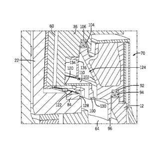
[0048] Figs. 3 and 4 illustrate the position of the counterweight 70
relative to the
crushing head 36 along the thin side of the eccentric 22. As discussed
previously, the drain holes
60 deposit oil collected from the upper sump 56 onto the radial flange 68 of
the eccentric 22 and
the horizontal floor of the counterweight 84. The counterweight 70 is attached
to the radial
flange 68 through the series of fasteners 132. In this position, the inner oil
chamber 122 receives
the oil from the drain holes 60 that is flung radially outward by the rotating
eccentric 22.
[0049] As illustrated in Fig. 4, the inner end 120 of the splash shield
110 is very closely.
spaced relative to the surface 134 of the crushing head 36. The close spacing
between the inner
end 120 of the splash shield 110 and the surface 134 greatly restricts the
amount of oil that can
splash over the splash shield 110. As stated previously, the inner oil chamber
is generally
defined by the splash shield 110, the floor 84 and the vertical separating
wall 100. During
operation, oil .flung radially outward by the rotating eccentric 22 is
entrapped within the inner oil
chamber 122 and quickly drains through the series of inner chamber drain holes
128. Since the
oil is forced radially outward by the centrifugal force created by the
rotating eccentric 22, the
inner chamber drain oil holes 128 are positioned as close as possible to the
vertical separating
wall 100 to prevent oil from pooling within the inner oil chamber 122. The oil
drained through
CA 02948189 2016-11-04
WO 2015/187421 PCT/US2015/032605
- 10 -
the inner chamber drain holes 128 passes through the counterweight and is
ultimately collected
within the main frame oil sump 64.
[0050] During high speed operation of the cone crusher, the eccentric 22
is rotating at a
relatively high speed which causes oil being drained through the drain holes
60 to be flung into
the inner oil chamber 122. This oil can create very small particles of oil or
a mist that may not
be entrapped and contained within the inner oil chamber 122. This additional
oil is then received
within the outer oil chamber 124. The outer oil chamber 124 is defined as the
area above the
splash shield 110 and between the vertical separating wall 100 and the inner
wall 102 of the
counterweight 70. Any oil received within the outer oil chamber 124 collects
and is drained out
of the outer oil chamber through the outer chamber drain holes 130. As
described above, since
the eccentric 22 is rotating, any oil received within the outer oil chamber
124 is forced radially
outward through the centrifugal force created by the rotating eccentric. Thus,
the outer chamber
drain holes 130 are positioned adjacent the inclined inner wall 102 of the
counterweight 70 to
help eliminate pooling of the oil within the counterweight. The oil drained
through the outer
chamber drain holes 130 is also directed to the main frame oil sump 64 by the
vertical flange 96.
The flange 96 protects the lower seal formed between the T-seal 92 mounted to
the
counterweight and the U-seal 94 mounted to the main frame 12.
[0051] As illustrated in Fig. 4, a head skirt 136 is mounted to the
crushing head 36 to
further deflect oil away from the seal created by the U-seal 104 and the T-
seal 106. The head
skirt 136 is attached to the crushing head 36 through a series of spaced
connectors, such as bolts.
Although the head skirt 136 deflects the oil-air mist away from the seals 104,
106, the head skirt
136 may not be required depending upon the close spacing between the inner end
120 of the
splash shield 110 and the surface 134 of crushing head 36, which controls how
much oil enters
the outer oil chamber 124 and the direction and velocity at which the oil
enters the outer oil
chamber 124.
[0052] Fig. 5 illustrates the general flow of lubricating oil within both
the inner oil
chamber 122 and the outer oil chamber 124. As previously described,
lubricating oil from the
drain hole 60 contacts the radial flange 68 of the eccentric 22 and the floor
84 of the
counterweight and enters into the inner oil chamber 122. The oil within the
inner chamber 122 is
entrapped by the generally horizontal splash shield 110 and the vertical
separating wall 100.
This collected oil drains through the inner chanther drain holes 128 and
ultimately travels to the
CA 02948189 2016-11-04
WO 2015/187421 PCT/US2015/032605
- 11 -
main .frame oil sump. Although most of this oil is captured in the inner oil
chamber 122, an oil-
air mist may pass between the slight gap formed between the inner end 120 of
the splash 'shield
110 and the surface .134. This oil mist contacts the head skirt 136 and is
directed downward onto
the upper .surface of the splash shield 110. The rotational movement of the
eccentric and
counterweight cause this small amount of oil to be thing radially outward and
into Contact with
the inclined inner wall 102. The oil .quickly drains out through the outer
chamber drain holes
130 positioned on the opposite side of the vertical separating wall 100 from
the inner chamber
drain holes 128. In this manner, the oil from both the inner chamber drain
holes 128 and the
outer chamber drain holes 130 move toward the main frame oil sump.
[0053] Fig. 6 clearly illustrates the position of the outer chamber drain
holes 130 and the
inner chamber drain holes 128 on the opposite sides of the vertical separating
wall 100. The
lower portion of the vertical separating wall 100 forms the divider 131
between the drain holes
128 and 130. Further, Fig. 6 illustrates the separation between the inner oil
Chamber 122 and the
outer oil chamber 124.
[0054] Fig. 7 illustrates the inner and outer chambers relative to the
thick side of the
eccentric 22. As illustrated in Fig. 7, the radial width of the splash plate
110 is less at the
location aligned with the thick portion of the eccentric as compared to the
thin portion of the
eccentric shown in Fig. 3 due to the increased eccentric thickness. However,
the splash shield
110 still combines with the vertical separating wall 100 to define the inner
oil chamber 122. The
outer oil chamber 124 is positioned on an opposite side of the vertical
separating wall 100. Oil
from drain holes 60 in this position drops directly onto the horizontal
counterweight floor 84.
[0055] Fig. 12 illustrates that the height of the vertical separating
wall 100 Changes from
the heavy side 74 to the light side 76 of the counterweight 70. Since the
heavy side 74 of the
counterweight 70 is aligned with the thin side of the eccentric, the height of
the vertical
separating wall 100 changes to accommodate the configuration of the eccentric
and the resulting
position of the head.
[0056] This written description uses examples to disclose the invention,
including the
best mode, and also to enable any person skilled in the art to make and use
the invention. The
patentable scope of the invention is defined by the claims, and may include
other examples that
occur to those skilled in the art. Such other examples are intended to be
within the scope of the
claims if they have structural elements that do not differ from the literal
language of the claims,
CA 02948189 2016-11-04
WO 2015/187421
PCT/US2015/032605
- 12 -
or if they include equivalent structural elements with .insubstantial
differences from the literal
languages of the claims.