Note: Descriptions are shown in the official language in which they were submitted.
CA 02948319 2016-11-07
1
Title of the Invention:
Method of Filling Liquid Content and Packing
Container Filled with Liquid Content
Technical Field:
[0001]
This invention relates to a method of filling a container
with a liquid content and, specifically, to a method of filling
a container with a highly viscous liquid content. The invention,
further, relates to a packing container filled with a liquid
content.
Background Art:
[0002]
Plastic containers are easy to form, can be inexpensively
produced, and have, therefore, been widely used in a variety
of applications. Specifically, olefin resin containers
directly blow-formed in the shape of a bottle and having an inner
surface formed by using an olefin resin such as low-density
polyethylene, have been favorably used as containers for
containing viscous slurry or paste-like liquid contents such
as ketchup and the like from such a standpoint that the contents
can be easily squeezed out.
[0003]
Further, the bottles containing highly viscous liquid
contents are, in many cases, stored in an inverted state so that
the contents can be quickly discharged or can be all used up
to its last drop without remaining in the bottles. When the
bottles are inverted, therefore, it is desired that the viscous
contents do not adhere or remain on the inner wall surfaces of
the bottles but fall down quickly.
[0004]
As a bottle for satisfying the above requirements, for
example, a patent document 1 is proposing a bottle of a
multilayered structure in which the innermost layer comprises
CA 02948319 2016-11-07
2
an olefin resin having an MFR (melt flow rate) of not less than
g/10 min.
In the above bottle of the multilayered structure, the
innermost layer has excellent wettability for the oily contents.
5 Therefore, if the bottle is inverted or is titled, the oily
content such as mayonnaise or the like falls down spreading over
the surface of the innermost layer and is completely discharged
without adhering or staying on the inner wall surface (surface
of the innermost layer) of the bottle.
10 [0005]
As bottles for containing viscous non-oily contents in
which plant fibers are dispersed in water like ketchup, patent
documents 2 and 3 are proposing polyolefin resin bottles having
an innermost layer that is blended with a saturated or
unsaturated aliphatic amide as the lubricant.
[0006]
The above patent documents 1 to 3 are all concerned to
plastic containers having improved slipping property to the
contents relying upon the chemical compositions of the
thermoplastic resin compositions forming the inner surfaces of
the containers, and are achieving slipping properties improved
to some extent. Due to limitation on the kinds of the
thermoplastic resins and on the additives, however, limitation
is also imposed on improving the slipping properties, and
striking improvements have not been achieved yet.
[0007]
In recent years, further, there has been proposed a
container having an inner surface that is a liquid-permeable
surface, i.e., having a surface that is a liquid-permeable
surface on the side that comes in contact with the content
(patent document 4) . In the above container, a film of a liquid
is formed on a portion that comes in contact with the liquid
content in the container, the film of the liquid exhibiting very
improved slipping property to the liquid content such as ketchup,
sauce, mayonnaise or the like.
CA 02948319 2016-11-07
3
In the containers of this kind, however, there still
remains a problem in regard to how to thinly, uniformly and
efficiently form the film of the liquid to improve slipping
property to the contents.
[0008]
A generally employed means comprises, for example,
forming a container, spraying a liquid onto a portion of the
container to where the content comes in contact to form a film
of the liquid thereon and, thereafter, filling up the content.
This means, however, necessitates the step of forming the liquid
film prior to filling the content causing, therefore, a decrease
in the productivity. Further, if it is attempted to uniformly
form the liquid film in the container by the above means, it
becomes necessary to spray the liquid in unnecessarily large
amounts. As a result, liquid reservoirs tend to form in the
container causing a large dispersion in the thickness of the
liquid film.
The present applicant has is proposed a means of forming
a liquid film by mixing a liquid into a resin that forms the
inner surface of a container (JP-A-2013-23468-
PCT/JP2014/052879) . According to this method, there is no need
of providing the step of forming the liquid film prior to filling
up the content and, therefore, the productivity is satisfactory.
The liquid film, however, is formed on the inner surface of the
container as the liquid bleeds out from the blend of resin that
is forming the inner layer. Therefore, the thickness of the
liquid film often becomes considerably small, and it is
difficult to reliably control the thickness of the liquid film.
Prior Art Documents:
Patent Documents:
[0009]
Patent document 1: JP-A-2007-284066
Patent document 2: JP-A-2008-222291
Patent document 3: JP-A-2009-214914
CA 02948319 2016-11-07
4
Patent document 4: W02014-010534
Outline of the Invention:
Problems that the Invention is to Solve:
[0010]
It is, therefore, an object of the present invention to
provide a method of filling a container with a liquid content,
the method being capable of efficiently forming a film of a
liquid on the inner surface of the container.
Another object of the present invention is to provide a
packing container filled with a liquid content by the above
filling method.
Means for Solving the Problems:
[0011]
According to the present invention, there is provided a
method of filling a container with a liquid content, comprising:
providing a liquid which is different from the liquid
content; and
forming a film of the liquid between an inner wall of the
container and the liquid content by filling the container with
the liquid content of which an outer circumference is at least
partly covered with the liquid or with a mixed liquid of the
immiscible liquid and the fluid content.
According to the above filling method, it is desired that:
(1) The liquid is a liquid immiscible with the liquid content;
(2) A multilayer filler is ejected, the multilayer filler
comprising a core layer of the liquid content and an outermost
layer of the liquid or the mixed liquid;
(3) The filling starts in a state where the ejected end of
the liquid content is covered with the liquid or with the mixed
liquid;
(4) Use is made of a multi-pipe nozzle comprising a center
pipe and an annular pipe surrounding the center pipe; and
the container is filled with the liquid content by
81801165
inserting the multi-pipe nozzle into the container, ejecting
the liquid content from the center pipe of the multi-pipe
nozzle, and ejecting the liquid or the mixed liquid from the
annular pipe of the multi-pipe nozzle;
5 (5) Filling is continued by ejecting the liquid or the mixed
liquid and the liquid content while gradually removing the
multi-pipe nozzle from the container as the amount of the
liquid content filled in the container increases; and
(6) The liquid or the mixed liquid is ejected at a timing
earlier than a timing at which the liquid content is ejected
from the center pipe.
[0012]
According to the present invention, further, there is
provided a packing container filled with a liquid content,
wherein in an unused and erected state, a head space is present
in the packing container, and a film of a liquid different from
the liquid content is selectively formed in a portion except
the head space.
In the packing container, it is desired that:
(7) The liquid is a liquid immiscible with the liquid
content; and
( 8 ) The container is in the shape of a bottle or a pouch.
[0012a]
According to an embodiment, there is provided a method
of filling a container with a liquid content, comprising:
providing a liquid which is different from the liquid content;
CA 2948319 2018-03-23
81801165
5a
forming a film of the liquid between an inner wall of the
container and the liquid content by filling the container with
the liquid content of which an outer circumference is at least
partly covered with the liquid or with a mixed liquid of the
immiscible liquid and the fluid content; and wherein the liquid
is a liquid immiscible with the liquid content.
[0012b]
According to another embodiment, there is provided a
method of filling a container with a liquid content, comprising:
providing a liquid which is different from the liquid content;
forming a film of the liquid between an inner wall of the
container and the liquid content by filling the container with the
liquid content of which an outer circumference is at least partly
covered with the liquid or with a mixed liquid of the immiscible
liquid and the fluid content; and wherein the container is filled
with the liquid content of which the outer circumference is at
least partly covered with the mixed liquid.
[0012c]
According to another embodiment, there is provided a
method of filling a container with a liquid content,
comprising: providing a liquid which is different from the
liquid content; forming a film of the liquid between an inner
wall of the container and the liquid content by filling the
container with the liquid content of which an outer
circumference is at least partly covered with the liquid or
with a mixed liquid of the immiscible liquid and the fluid
content; and wherein the filling starts in a state where the
CA 2948319 2018-03-23
81801165
5b
ejected end of the liquid content Is covered with the liquid or
with the mixed liquid.
Effects of the Invention:
[0013]
In the filling method of the present invention, the
container is filled with a liquid content and, at the same
time, a film of a liquid (e.g., liquid for reforming the
surface) is formed making it possible to effectively avoid a
decrease in the productivity caused by the operation for
forming the liquid film.
In the above method, further, the container is filled with
the liquid content which is in a state of being wrapped with
the liquid film. Therefore, the liquid film is necessarily
present between the inner surface of the container and the
CA 2948319 2018-03-23
CA 02948319 2016-11-07
6
liquid content filled in the container. As a result, the liquid
exhibits improved slipping property to the liquid content
maintaining reliability and stability without dispersion.
Further, when the container of the shape of a bottle is
filled with the liquid content, the container, usually, forms
a space called head space. If the filling method of the present
invention is adopted, however, the film of the liquid is
selectively formed in a region where the content is present
provided the container is in an unused and erected state, and
no liquid film is formed in the head space. Namely, in the
present invention, the film of the liquid is formed in only the
region where it is desired to improve the slipping property to
the liquid content. Therefore, the cost is effectively
prevented from increasing unnecessarily.
Brief Description of the Drawings:
[0014]
Fig. 1: a partial sectional view showing the state of an inner
surface of a packing container formed relying on a filling
method of the present invention.
Fig. 2: a view showing the state of an empty container which
is a directly blow-formed bottle representing the most
preferred packing container having the cross section shown in
Fig. 1.
Fig. 3: a perspective view showing an end portion of a multiple
nozzle used for the filling method of the present invention.
Fig. 4: a view illustrating the filling method of the present
invention.
Modes for Carrying Out the Invention:
[0015]
<Form of the packing container>
Reference is now made to Fig. 1 which shows the state of
an inner surface of a packing container to which the filling
method of the present invention is adopted. The container has
CA 02948319 2016-11-07
7
a film 3 of a liquid formed on the inner surface of a container
material 1 to reform the surface thereof. A liquid content is
filled up on the liquid film 3. Namely, in the filling method
of the present invention, the liquid film 3 is formed and,
substantially at the same time, the liquid content is filled
up.
[0016]
The container material 1 has a structure that is capable
of stably holding the film 3 of the liquid formed on the inner
surface thereof. The container material will be a resin, a
glass, a paper or a metal. Of them, it is desired that the
container material has a structure of which the inner surface
is made of a resin in which the liquid permeates to a suitable
degree to improve affinity between the liquid and the container
material effectively avoiding the liquid from splitting off.
As the resin, there can be exemplified thermoplastic
resins that can be formed into containers, such as polyesters
as represented by polyethylene terephthalate, and olefin resins.
Specifically, there can be exemplified olefin resins and, in
particular, low-density polyethylene, straight chain
low-density polyethylene, medium- or high-density
polyethylene, polypropylene, poly 1-butene, and poly
4-methyl-1-pentene from such a standpoint that they can be
favorably used for forming containers such as directly
blow-formed containers for containing viscous liquid contents
that require improved slipping property. There can be also
favorably used, as a matter of course, random or block
copolymers of a-olefins, such as ethylene, propylene, 1-butene,
and 4-methyl-1-pentene. There can be, further, used cyclic
olefin copolymers as disclosed in JP-A-2007-284066.
[0017]
So far as the inner surface is formed by using the
above-mentioned thermoplastic material, the container
material 1 is not limited to the single-layer structure but may
have a multilayer structure comprising a resin layer forming
CA 02948319 2016-11-07
8
the inner layer and, formed thereon, other layers such as of
resin, glass, paper or metal.
[0018]
In the above multilayer structure, it is desired to
provide an intermediate layer between the inner layer and the
outer layer of the above-mentioned olefin resin, the
intermediate layer being a gas barrier layer formed by using
an ethylene-vinyl alcohol copolymer (saponified product of an
ethylene-vinyl acetate copolymer) or an aromatic polyamide.
Most desirably, the intermediate layer is a gas barrier layer
of the ethylene-vinyl alcohol copolymer. By forming the gas
barrier layer as the intermediate layer, the oxygen barrier
property can be imparted. Specifically, the ethylene-vinyl
alcohol copolymer exhibits very excellent oxygen barrier
property and, therefore, effectively suppresses the oxidation
or deterioration of the content caused by oxygen that has
permeated through and ensures excellent content
preservability.
[0019]
If the above gas barrier layer is provided, it is also
desired to provide an adhesive resin layer to improve
adhesiveness to the inner and outer layers, and to prevent
delamination. This enables the intermediate gas barrier layer
to be firmly adhered and fixed to the inner and outer layers.
The adhesive resins used for forming the adhesive resin layer
have been known per se. For instance, there have been used
resins that have a carbonyl group (>C=0) on the main chain or
on the side chains in an amount of 1 to 100 meq/100 g of the
resin and, specifically, 10 to 100 meq/100 g of the resin.
Concretely, there are used, as adhesive resins, an olefin resin
graft-modified with a carboxylic acid such as maleic acid,
itaconic acid or fumaric acid or an anhydride, amide or ester
thereof; an ethylene-acrylic acid copolymer; an ionically
crosslinked olefin copolymer; and an ethylene-vinyl acetate
copolymer.
CA 02948319 2016-11-07
9
[0020]
The thickness of the container material 1 is set depending
on the form of the container so as to exhibit desired strength,
flexibility, capability and squeezing property. For instance,
the thickness is set to be about 100 to about 800 ktm in the
case of a directly blow-formed plastic container that is used
preferably for being filled with a viscous content.
If the multilayer structure is employed, further, the gas
barrier layer (intermediate layer) may, desirably, have a
thickness of, usually, 1 to 50 um and, specifically, 9 to 40
,um while the adhesive resin layer may have such a thickness
as to exhibit a suitable degree of adhesive force and, usually,
a thickness of about 0.5 to about 20 urn and, preferably, about
1 to about 8 ,um.
[0021]
In the container material 1 having the multilayer
structure, further, any one of the multiplicity of layers may
be a reground resin layer formed by using a mixture of a scrap
resin generated during the formation of the containers and a
virgin resin used for forming the outermost layer. In this case,
the amount of the scrap resin should be about 10 to about 60
parts by weight per 100 parts by weight of the virgin resin
forming the outermost layer from a standpoint of reutilizing
the resources yet maintaining the formability. The thickness
of the layer neighboring the outermost layer may differ
depending on the size of the packing container or the kind of
the content, but should be such that the whole thickness of the
container wall does not become unnecessarily large and that the
scrap resin can be effectively utilized. That is, the thickness
of the layer neighboring the outermost layer is set to be about
20 to about 400 um.
[0022]
The container used in the invention can assume the forms
of pouch, bottle, cup and the like. In the invention, the liquid
film 3 helps improve slipping property (slide-down property)
CA 02948319 2016-11-07
to the liquid content. As described earlier, therefore, the
directly blow-farmed container that is capable of easily
discharging the viscous content upon being squeezed, is suited
as the container material 1. Fig. 2 shows the state of an empty
5 container which is a directly blow-formed container for
containing food right after it was formed.
The empty container generally designated at 10 has a mouth
portion 13 with a screw thread at an upper portion thereof. A
blow-formed portion 15 is continuous to the mouth portion 13,
10 and includes a body portion and a bottom portion so formed as
to close the body portion.
A closing portion 17 is formed at the upper part of the
mouth portion 13 to close it. The closing portion 17 is forming
a small hole 17a in which a feed pipe will be inserted to feed
a fluid for blow-forming. The small hole 17a is communicated
with the interior of the empty container 10.
That is, like in the conventional known method, a molten
resin (melt of a resin for forming) is extruded
(extrusion-formed) into a preform of the shape of a pipe of which
the bottom portion is closed by pinch-off. Through the small
hole 17a formed in the preform, a fluid for blow-forming is fed
into the preform maintained at a predetermined temperature for
blow-forming to impart the shape of a container thereto. The
container is thus directly blow-formed.
[0023]
If it is attempted to form a container different from the
directly blow-formed container, a preform of the shape of a test
tube is formed by the injection-forming, and a fluid maintained
at a predetermined temperature for stretch-forming is blown
therein to biaxially stretch-blow-form the preform. The
preform is thus formed into the shape of a container; i.e., an
empty container is obtained for being filled with a content.
[0024]
<Liquid and liquid content>
The liquid film 3 is formed on the inner surface of the
CA 02948319 2016-11-07
11
container by using a liquid which is immiscible with the fluid
content filled up in the container, and works to improve
slipping property (slide-down property) to the liquid content.
If the liquid is miscible with the content, then the liquid
is mixed with the content and is split off the inner surface
of the container. Namely, the liquid film 3 is broken down.
The liquid immiscible with the content and works to
improve slipping property to the content is a liquid that is
immiscible with the content or, roughly speaking, is a liquid
which is oleophilic to the aqueous content or is water or a liquid
which is hydrophilic to the oily content. Usually, a liquid
can be used if it is capable of holding the liquid film 3 in
an amount of not less than 0.1 g/m2 and, specifically, not less
than 0.5 g/m2 in a state where the container is filled with the
content. Specifically, a liquid produces a high lubricating
effect if its surface tension to the inner surface of the
container is greatly different from its surface tension to the
content, and the liquid of this kind is suited for the present
invention.
[0025]
In the invention, the liquid content to be contained in
the container is, preferably, a liquid content that has no
shape-retaining property but has fluidity so as to utilize the
slipping property of the liquid film 3 to a maximum degree.
Namely, preferred examples of the liquid content are viscous
paste-like or slurry liquid substances (e.g., having
viscosities at 25 C of not less than 100 mPa.$) or, concretely,
ketchup, aqueous paste, honey, various sauces, mayonnaise,
cosmetic liquid such as lotion, liquid detergent, shampoo,
rinse, conditioner and the like. Namely, in the invention, the
liquid film 3 exhibits a favorable slipping property.
Therefore, even a viscous liquid material can be quickly
discharged without adhering or remaining on the inner surface
of the container if the container is tilted or inverted.
Specifically, with the directly blow-formed container for foods
CA 02948319 2016-11-07
12
described above, the content can be squeezed out by squeezing
the body portion. Therefore, ketchup and mayonnaise are
contained as contents.
[0026]
In the invention, as concrete examples of the liquid
selected depending on the kind of the content contained in the
container, i.e., as the most desirable liquids for the
water-containing contents (e.g., ketchup, sauce), there can be
used silicone oil, glycerin fatty acid ester, liquid paraffin
and edible oil and fat. Particularly preferred examples are
glycerin fatty acid esters as represented by medium-chain fatty
acid triglyceride, glycerin trioleate and glycerin
diacetomonooleate, as well as liquid paraffin and edible oil
and fat. They are difficultly volatile and have been approved
as food additives and, further, have such advantages that they
are odorless and do not impair the flavors of the contents.
For the oily contents, further, there can be used water
or ionic liquid which is highly hydrophilic provided its boiling
point lies within the above-mentioned range.
Further, for the emulsion type liquid materials, there
can be favorably used, as liquids, silicone oil, glycerin fatty
acid ester, liquid paraffin and edible oil and fat.
[0027]
<Filling up the content and forming the liquid film>
In the present invention, the liquid film 3 is formed on
the container material 1 that has the above-mentioned form
substantially simultaneously with the filling up of the liquid
content. Though not limited thereto only, described below is
a concrete example of the invention using a multi-pipe nozzle
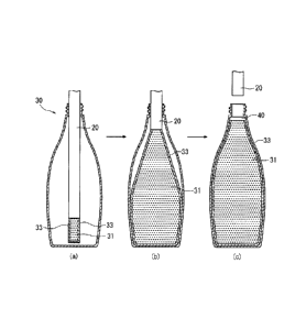
20 of a structure shown in Fig. 3.
[0028]
In Fig. 3, the multi-pipe nozzle 20 includes a center pipe
21 and an annular pipe 23 formed on the outer side so as to
surround the center pipe 21. That is, the center pipe 21 is
used for filling up the liquid content that forms the core layer
CA 02948319 2016-11-07
13
while the annular pipe 23 is used for feeding the liquid that
forms the outermost layer.
[0029]
By using the above multi-pipe nozzle 20, the content is
filled up and the liquid film 3 is formed according to a process
shown in Fig. 4.
[0030]
That is, referring to Fig. 4(a), the multi-pipe nozzle
20 is inserted in an empty container 30 (e.g., the empty
container 10 shown in Fig. 2 from which the closing portion 17
is cut away), and the interior of the container starts filled
up with a liquid content 31 from the center pipe 21 and with
a liquid 33 from the annular pipe 23. Here, the liquid 33 is
fed slightly earlier than the liquid content 31. Namely, the
liquid content 31 is filled up in a state where the end of the
center pipe 21 of the multi-pipe nozzle 20 is covered with the
liquid 33.
As shown in Fig. 4(a), therefore, the liquid content 31
fills up the interior of the empty container 30 in a manner of
being covered with the liquid 33.
[0031]
The liquid content 31 is thus filled up. Referring next
to Fig. 4(b), the multi-pipe nozzle 20 is gradually pulled up
so that the content 31 (and the liquid 33) filling up surrounding
the multi-pipe nozzle 20 will not enter into the multi-pipe
nozzle 20. After the container is filled up with the content
31 in a predetermined amount, feeding of the content 31 and
feeding of the liquid 33 are discontinued, and the multi-pipe
nozzle 20 is pulled out from the container 30 as shown in Fig.
4(c). Operation for filling up the content 31 and the liquid
33 is now completed. Finally, the upper end of the container
30 is sealed with a lid member or the like. There is thus
obtained a desired packing container filled up with the liquid
content 31.
[0032]
CA 02948319 2016-11-07
14
In the packing container obtained as described above, a
film of the liquid 33 is necessarily formed between the content
31 and the inner surface of the container 30 as shown in Fig.
4(c). The liquid film exhibits improved slipping property
maintaining reliability without dispersion.
[0033]
In carrying out the above operation, the rate of feeding
the liquid 33 and the rate of filling up the content 31 may be
so set that the thickness of the film of the liquid 33 lies in
a suitable range. For instance, the rates thereof may be so
set that the content 31 will not be fed at such a large rate
as to break the surrounding film of the liquid 33.
As described above, it is made possible to eject a
multilayer filler comprising the core layer of the liquid
content and the outermost layer of the liquid. The filling
method of the present invention fills up the liquid content of
which the outer circumference is at least partly covered with
the liquid. In addition to the above-mentioned method, it is
also allowable to eject the multilayer filler by bringing the
liquid content into contact with the liquid 33 on the side
(upstream) of feeding the liquid content. Moreover, the liquid
content that is ejected may be coated with the liquid. Or a
mist of liquid may be sprayed onto the liquid content.
[0034]
In order that the film of the liquid 33 is little broken,
it is desired that the liquid 33 has a viscosity smaller than
a viscosity of the content 31 at a temperature at which the
content 31 is filled. This is because by setting the viscosity
of the liquid 33 to be smaller than the viscosity of the content
31, the liquid 33 having a small viscosity is allowed to easily
follow the deformation of the content 31 despite it is filled
up at a large rate and, therefore, the liquid film is effectively
prevented from breaking.
It is, further, desired that a surface tension of the
liquid 33 is smaller than a surface tension of the content 31.
CA 02948319 2016-11-07
This is because by setting the surface tension of the liquid
33 to be smaller than the surface tension of the content 31,
the liquid 33 is allowed to easily wet and spread on the content
31 when it is filled up. Therefore, this is also effective in
5 preventing the film of the liquid 33 from breaking despite the
content 31 is filled up at an increased rate.
[0035]
According to the filling method of the present invention,
as described above, the liquid content 31 is filled up and, at
10 the same time, the film of the liquid 33 is formed preventing
a decrease in the productivity caused by the operation for
forming the liquid film. The thickness of the liquid film, too,
can be easily adjusted by adjusting the rates of feeding the
content 31 and the liquid 33.
15 Further, as will also be understood from Fig. 4(c), ahead
space 40 is, usually, formed in the thus obtained packing
container. In the present invention, however, when the
container is in an unused and erected state, the film of the
liquid 33 is selectively formed in only a region where the
content 31 is present but is not formed in the head space.
Therefore, the amount of the liquid 33 that is used can be
minimized to effectively avoid an increase in the cost.
[0036]
In the above embodiment, further, the liquid immiscible
with the content was most desirably used as the liquid 33 to
improve the slipping property. It is, however, also allowable
to use a mixed liquid of the liquid for improving the slipping
property and the liquid content. In this case, the mixed liquid
is ejected from the annular pipe 23 to cover the liquid content
31 that is ejected from the center pipe 21. Here, however, the
covering layer undergoes phase separation; i.e., the liquid
content in the mixed liquid merges with the liquid content 31
ejected from the center pipe 21 and the liquid for improving
the slipping property is repelled into the outer layer to form
the liquid film.
CA 02948319 2016-11-07
16
[0037]
In the foregoing was described the filling method with
reference to the case of filling up the container of the shape
of a bottle. So far as the multi-pipe nozzle 20 is used to fill
up the content 31 and to feed the liquid 33, however, the filling
method of the invention is not limited to the case of filling
up the container of the bottle shape only but can, as a matter
of course, be adopted to the cases of filling up the containers
of any other shapes such as bags and the like, too.
Description of Reference Numeral:
[0038]
1: container material
3: liquid film
10: empty container
13: mouth portion
15: blow-formed portion
17: closing portion
20: multi-pipe nozzle
21: center pipe
23: annular pipe
30: empty container
31: liquid content
33: liquid