Note: Descriptions are shown in the official language in which they were submitted.
81800924
RADIUS HINGE
SUMMARY
[0001] According to one aspect of the present invention, there is
provided a computing
device, comprising: a display portion that includes a display screen and an
input portion that
includes an input device; and, a hinge assembly rotatably securing the display
and input
portions, the hinge assembly including: at least first and second adjacent
offset stacks, the first
stack comprising a first display portion element, a first timed link element,
and a first input
portion element, the second stack comprising a second display portion element,
a second
timed link element, and a second input portion element, the first and second
timed link
elements having generally opposing first and second ends and a first hole
formed through the
first end and a second hole formed through the second end, and, a first axis
pin passing
through the second hole of the first timed link element of the first stack and
the first hole of
the second timed link element of the second stack and a second axis pin that
passes through
the first hole of the first timed link element of the first stack and the
second display portion
element of the second stack and a third axis pin that passes through the first
input portion
element of the first stack and the second hole of the second timed link
element of the second
stack, such that the first, second, and third axis pins secure the second
stack in an offset
manner relative to the first stack.
[0001a] According to another aspect of the present invention, there is
provided a
computing device, comprising: a display portion that includes a display screen
and an input
portion that includes an input device; and, a radius hinge assembly rotatably
securing the
display and input portions and configured to facilitate a curvilinear
articulation that allows
360 degrees of relative rotation between the display and input portions, the
radius hinge
assembly including: at least first and second adjacent offset stacks, the
first stack comprising a
first display portion element directly engaging the display portion and a
first input portion
element directly engaging the input portion, the first display portion element
positioned next
to a first timed link element of the first stack, the second stack comprising
a second display
portion element directly engaging the display portion and a second input
portion element
1
Date Recue/Date Received 2020-05-25
81800924
directly engaging the input portion, the second display portion element
positioned next to a
second timed link element of the second stack, the first stack being offset
from the second
stack such that an individual axis of the curvilinear articulation that allows
the 360 degrees of
relative rotation passes through the first timed link element and does not
pass through the
second timed link element.
[0001b] According to still another aspect of the present invention, there is
provided a
computing device, comprising: a first portion that includes an electronic
component and is
electrically connected by conductors to a second portion that includes a
second electronic
component; and, a radius hinge assembly rotatably securing the first and
second portions, the
radius hinge assembly including at least first, second, and third offset
stacks that collectively
control rotation of the first and second portions relative to one another
while preserving a
minimum bend radius for the conductors between the first portion and the
second portion, the
first, second, and third offset stacks having a same number of parts including
respective first
portion elements directly engaging the first portion, respective second
portion elements
directly engaging the second portion, and timed link elements, the second
stack being offset
from the first and third stacks such that an axis of the rotation of the first
and second portions
passes through an individual first portion element of the first stack, an
individual timed link
element of the second stack, and an individual first portion element of the
third stack.
[0001c] According to yet another aspect of the present invention, there is
provided a
computing device, comprising: a display portion that includes a display screen
and a display
housing, and an input portion that includes an input device and an input
housing; and, a hinge
assembly rotatably securing the display and input portions, the hinge assembly
including: at
least first and second adjacent offset stacks, each individual stack of the at
least first and
second adjacent offset stacks comprising a display portion element secured to
the display
housing, a single timed link element, and an input portion element secured to
the input
housing, the single timed link element having opposing first and second ends
and a first hole
formed through the first end and a second hole formed through the second end,
said first and
second ends and first and second holes being identified along the stack
starting from the
display portion element toward the input portion element, and, a first axis
pin passing through
the second hole of the timed link element of the first stack and the first
hole of the timed link
la
Date Recue/Date Received 2020-05-25
81800924
element of the second stack that secures the second stack in an offset manner
relative to the
first stack, the offset manner being defined by a pitch diameter of the second
end of the timed
link element of the first stack and a first end of the timed link element of
the second stack;
wherein relative to the first stack, the first end of the timed link element
does not engage the
display portion element and the second end engages the input portion element
in a no-slip
one-to-one rotational engagement, and, relative to the second stack, the first
end of the timed
link element engages the display portion element in a no-slip one-to-one
rotational
engagement and the second end does not engage the input portion element.
10001d1 According to a further aspect of the present invention, there is
provided a
computing device, comprising: a display portion that includes a display screen
and a display
housing and an input portion that includes an input device and an input
housing; and, a hinge
assembly rotatably securing the display and input portions, the hinge assembly
including: at
least first and second adjacent offset stacks, each individual stack of the at
least first and
second adjacent offset stacks comprising a display portion element secured to
the display
housing, a plurality of serially arranged timed link elements, and an input
portion element
secured to the input housing, wherein the plurality of timed link elements
comprises a first
and a last time link elements, wherein each timed link element has opposing
first and second
ends and a first hole formed through the first end and a second hole formed
through the
second end, wherein the first and the last time link elements, the first and
second ends and the
first and second holes of a time link element are identified along the stack
starting from the
display portion element toward the input portion element, and wherein, for
successive timed
link elements of the plurality of timed link elements in the stack, the second
end of a timed
link element engages the first end of its successive timed link element; and a
first axis pin
passing through the second hole of the first timed link element of the first
stack and the first
hole of the first timed link element of the second stack that secures the
second stack in an
offset manner relative to the first stack, the offset manner being defined by
a pitch diameter of
the second end of the first timed link element of the first stack and a first
end of the first timed
link element of the second stack; wherein relative to the first stack, the
first end of the first
timed link element does not engage the display portion element and the second
end of the last
timed link element engages the input portion element in a no-slip one-to-one
rotational
lb
Date Recue/Date Received 2020-05-25
81800924
engagement, and, relative to the second stack, the first end of the first
timed link element
engages the display portion element in a no-slip one-to-one rotational
engagement and the
second end of the last timed link element does not engage the input portion
element.
BRIEF DESCRIPTION OF THE DRAWINGS
[0001e] The accompanying drawings illustrate implementations of the concepts
conveyed
in the present document. Features of the illustrated implementations can be
more readily
understood by reference to the following description taken in conjunction with
the
accompanying drawings. Like reference numbers in the various drawings are used
wherever
feasible to indicate like elements. Further, the left-most numeral of each
reference number
conveys the FIG. and associated discussion where the reference number is first
introduced.
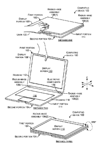
[0002] FIG. 1 is an example device that includes a radius hinge example
in accordance
with some implementations of the present concepts.
[0003] FIGS. 2-4 are elevational views of a radius hinge example in
accordance with
some implementations of the present concepts.
[0004] FIGS. 5-7 are perspective views of a radius hinge example in
accordance with
some implementations of the present concepts.
[0005] FIG. 8 is an exploded perspective view that is similar to the
perspective view of
FIG. 7.
[0006] FIG. 9 is an elevational view of a portion of the radius hinge
example shown in
FIGS. 1-8.
[0007] FIGS. 10-11 are perspective views of a radius hinge example in
accordance with
some implementations of the present concepts.
[0008] FIGS. 12-13 are perspective views of a radius hinge example in
accordance with
some implementations of the present concepts.
1 c
Date Recue/Date Received 2020-05-25
81800924
[0009] FIG. 14 is an exploded perspective view that is similar to the
perspective view of
FIG. 12.
[00010] FIG. 15 is a perspective view of a portion of the radius hinge example
shown in
FIG. 14.
[00011] FIG. 16 is an elevational view of a portion of the radius hinge
example shown in
FIGS. 10-15.
DESCRIPTION
[00012] The present concepts relate to a seamless radius hinge assembly that
can offer up
to full 360 degree rotation. The seamless radius hinge assembly can be
employed to rotatably
connect two portions of electronic or computing devices while protecting
electronic
components that span between the two portions. Traditional hinges tend to
pivot
id
Date Recue/Date Received 2020-05-25
CA 02948527 2016-11-08
WO 2015/191408 PCT/US2015/034611
around a single axis and can lead to pinching or other damage to the
electronic components.
In contrast, the seamless radius hinge assembly can offer (e.g., maintain) a
minimum bend
radius that can protect the electronics.
[00013] Introductory FIG. 1 shows an example of a computing device 100 that
has first
and second portions 102 and 104 that are rotatably secured together by a
radius hinge
assembly 106 (in this case, two radius hinge assemblies 106(1) and 106(2). In
this instance,
first portion 102 is manifest as a display portion 108 that includes a display
screen 110 in a
housing 112. Second portion 104 is manifest as an input portion 114 that
includes an input
device 116 and a housing 118. In this case the input device 116 is manifest as
a keyboard
and/or a track pad or touch pad. Other implementations can employ other input
devices.
For instance, the input device 116 could be manifest as a touch sensitive
display screen.
Electronic components 120 in the form of conductors can pass from the first
portion 102 to
the second portion 104 proximate to the radius hinge assembly 106.
[00014] The radius hinge assembly 106 can offer 360 degrees of rotation
between the
first portion 102 and the second portion 104 while protecting the electronic
components 120
from damage associated with normal hinges. For example, instance one shows
about five
degrees of rotation between the first and second portions as a user 122
inserts his/her thumb
between the portions. Instance two shows about 100 degrees of rotation and
instance three
shows about 360 degrees of rotation.
[00015] Further, the radius hinge assembly 106 can be thought of as a
progressive hinge
that can offer progressive resistance as the angle between the first portion
102 and the second
portion 104 increases. For instance, in some implementations, at instance one
the radius
hinge assembly 106 can offer relatively low resistance to movement so the user
122 can tilt
first portion 102 up and away from second portion 104 without holding the
second portion
104 down with their second hand. Instance 2 shows the first portion 102
rotated
approximately 100 degrees from second portion 104. At this angle the radius
hinge
assembly 106 can offer relatively greater resistance to movement and thus can
hold the first
portion stable for use. Instance three shows the second portion rotated all
the way around
to 360 degrees relative to the first portion (the computing device 100 has
also been flipped
so that the display screen 110 is facing up). In this configuration, the
display screen can be
used in a tablet-like manner.
[00016] The radius hinge assembly 106 can offer 360 degrees of rotation
between the
first and second portions while protecting the electronic components 120 from
damage
associated with normal hinges.
2
CA 02948527 2016-11-08
WO 2015/191408 PCT/US2015/034611
[00017] FIGS. 2-9 collectively show one implementation of radius hinge
assembly 106
introduced above. This variation is distinguished via use of a suffix "A"
(e.g., 106(A)).
FIGS. 2-3 and 7-8 show the radius hinge assembly 106(A) in the 'open' position
(e.g., 180
degrees). FIGS. 4-6 show the radius hinge assembly 106(A) in a 'closed'
position (e.g.,
zero degrees). FIGS. 10-16 show another radius hinge implementation which is
designated
106(B).
[00018] Radius hinge assembly 106(A) may include at least first and
second adjacent
offset stacks 202. The illustrated configuration includes five stacks 202(1)-
202(5),
however, more or less stacks may be employed. The number of stacks can be
increased to
add additional resistance to the radius hinge assembly as may be desired for a
particular
application. As may be most readily appreciated in the exploded view of FIG.
8, individual
stacks may include a display portion element (e.g., display element) 804, a
timed link
element 806, and an input portion element (e.g., input element) 808. To
improve readability
of the drawing page only elements of the first two stacks 202(1) and 202(2)
are designated.
However, the stacks generally repeat themselves in an alternating manner.
Thus, stack
202(3) and 202(5) are similar to stack 202(1) and stack 202(4) is similar to
stack 202(2).
Also, not every element is designated on every FIG. 2-9. In this
implementation each stack
includes a single timed link element 806. FIGS. 10-16 show another
implementation where
each stack includes multiple serially arranged timed link elements.
[00019] In the illustrated configuration of FIGS. 2-9, display portion element
804 can be
secured to the display housing 112 (FIG. 1, Instance two). Similarly, the
input portion
element 808 can be secured to the input portion housing 118 (FIG. 1, Instance
two). Relative
to stacks 202(1), 202(3), and 202(5) a terminal end 810 of the display portion
element 804(1)
is not geared to engage the timed link element 806(1). In contrast, relative
to stacks 202(2)
and 202(4) the terminal ends 810 are geared to engage the timed link elements
806. Relative
to stacks 202(1), 202(3), and 202(5) a terminal end 812 of the input portion
element 808 is
geared to engage the timed link elements 806. In contrast, relative to stacks
202(2) and
202(4) the terminal ends 812 are not geared to engage the timed link elements
806.
[00020] The timed link elements 806 can have generally opposing first and
second ends
814 and 816 and a first hole 818 formed through the first end 814 and a second
hole 820
formed through the second end 816. These elements are labeled without
specificity in a
callout 822 relative to FIG. 8 to avoid designator lines obscuring the main
drawings. Note
that in the illustrated configuration, individual timed link elements are
geared on both ends.
This configuration can allow radius hinge assemblies 106(A) to be constructed
with fewer
3
CA 02948527 2016-11-08
WO 2015/191408 PCT/US2015/034611
different types of elements. However, note that the first end 814 of timed
link element
806(1) does not engage terminal end 810 of display portion element 804(1) and
thus the
gear teeth are not utilized and thus could be eliminated. Similarly, the
second end 816 of
timed link element 806(2) could also eliminate the gear teeth because they do
not engage
terminal end 812(2) of input portion element 808(2).
[00021] Radius hinge assembly 106(A) may include a generally elongate
axis pin
824(1) that passes through the second hole 820 of the timed link element
806(1) of the first
stack 202(1). The axis pin 824(1) can also pass through the first hole 818 of
the timed link
element 806(2) of the second stack 202(2) to secure the second stack 202(2) in
an offset
manner relative to the first stack 202(1). In this case, the offset manner can
be defined by a
pitch diameter of the timed link elements. FIG. 9 shows timed link element
806(1) and
timed link element 806(2) at instance one. Timed link element 806(2) is shown
in dashed
lines since part of timed link element 806(2) is behind timed link element
806(1). Instance
two shows the addition of pitch diameter 902 as defined by the second end 816
of the first
timed link element 806(1) and a first end 814 of the second timed link element
806(2).
[00022] Returning to FIG. 8, the radius hinge assembly 106(A) may include a
second
axis pin 824(2) and a third axis pin 824(3) that are generally parallel to the
first axis pin
824(1). The second axis pin 824(2) can pass through a hole 826 in the display
element
804(2) of the second stack 202(2) and the hole 818 in the first end of the
timed link element
806(1) of the first stack 202(1). The third axis pin 824(3) can pass through
the hole 820 in
the second end 816 of the timed link element 806(2) of the second stack 202(2)
and a hole
828 in the input portion element 808(1) of the first stack 202(1).
[00023] In the present configuration, the second axis pin 824(2) and the third
axis pin
824(3) are on opposite sides of the (first) axis pin 824(1). This
configuration may include
a fourth axis pin 824(4) that is adjacent to the second axis pin 824(2) and
distal to the axis
pin 824(1) and a fifth axis pin 824(5) that is adjacent to the third access
pin 824(3) and distal
to the axis pin 824(1). The fourth axis pin 824(4) can pass through a second
hole 830 in the
display element 804(2) of the second stack 202(2) and a hole 831 in the
display element
804(1) of the first stack 202(1). The fifth axis pin 824(5) can pass through a
hole 832 in the
input portion element 808(2) of the second stack 202(2) and a second hole 834
of the input
portion element 808(1) of the first stack 202(1).
[00024] In this implementation, the axis pins 824 can be manifest as threaded
bolts. The
bolts can pass through link covers 836 (not all of which are designated with
specificity)
through the stacks 202(1)-202(5) and through another set of link covers 838
and a set of
4
CA 02948527 2016-11-08
WO 2015/191408 PCT/US2015/034611
threaded nuts 840. In the present configuration the second axis pin 824(2) and
the fourth
axis pin 824(4) share common link covers on each side of the first and fifth
stacks and the
axis pin 824(1) and the third axis pin 824(3) share other common link covers
on each side
of the first and fifth stacks. The threaded bolts, link covers, and the nuts
840 may provide
.. a compressive force to squeeze the stacks against one another to create
friction between the
adjacent elements. In some implementations, an axial load may be applied
between
elements through the use of a spring washer between the nuts 840 and the link
covers 838
to create and maintain the desired friction interface between the stacks. The
spring washer
can help to maintain the axial load even as elements wear. At some point if
the spring
washer cannot maintain the load, these implementations can be readily adjusted
by
tightening the bolt/nuts to increase the friction.
[00025] The illustrated configuration may be viewed as employing axial
friction to
control hinge stiffness. Other types of axial friction configurations are
contemplated. An
alternative configuration can utilize oversize axis pins 824 (relative to the
holes). The
oversize axis pins can be force fitted through the holes in the stacks 202 to
create a friction
fit between the axis pin and the elements defining the holes. This
configuration may be
viewed as employing radial friction to control hinge stiffness and other
configurations are
contemplated.
[00026] In this implementation relative to the first stack 202(1), the first
end 814 of the
timed link element 806(1) does not engage the display element 804(1). The
second end 816
can engage the input portion element 808(1) in a no-slip one-to-one rotational
engagement.
Relative to the second stack 202(2), the first end 814 of the timed link
element 806(2) can
engage the display portion element 804(2) in a no-slip one-to-one rotational
engagement
and the second end 816 does not engage the input portion element 808(2). In
this case, the
no-slip one-to-one rotational engagement is accomplished by intermeshing gears
that cause
the radius hinge assembly to rotate around axis pins 824(1), 824(2), and
824(3)
simultaneously. Other implementations can utilize other gear profiles and/or
types of gears
and/or can utilize non-geared solutions such as smooth but high friction
radial surfaces.
Characterized from one perspective, the radius hinge implementation
illustrated in FIGS. 2-
9 can simultaneously pivot around three axes (e.g., axis pins 824(1), 824(2),
and 824(3)).
The discussion that follows describes a radius hinge implementation that can
simultaneously
pivot around five axes. Given equivalent size elements, increasing the number
of axes can
increase the hinge radius. Another way of increasing the hinge radius can
entail increasing
the pitch diameter while maintaining the same number of axes.
5
CA 02948527 2016-11-08
WO 2015/191408 PCT/US2015/034611
[00027] FIGS. 10-16 show another radius hinge assembly 106(B) that is similar
to radius
hinge assembly 106(A) described above relative to FIGS. 2-9. As such, not all
elements are
re-introduced here for sake of brevity. The suffix "(B)" is utilized to
distinguish elements
of radius hinge assembly 106(B) from the implementations described above. In
this case,
FIG. 14 is an exploded perspective view that is similar to FIG. 8 and which
lends itself to
visualization of the elements. This implementation includes nine stacks
202(1)(B)-
202(9)(B). Other numbers of stacks are contemplated. Further, the stacks are
secured by
axis pins 824(B)(1)-824(B)(9), link covers 836(B) and 838(B), and nuts 840(B).
This
implementation employs more axis pins, link covers, and nuts than the
implementation
described above relative to FIGS. 2-9. The functionality, however, remains
similar. As
such, these elements are not discussed in detail relative to FIGS. 10-16. Due
to the amount
of elements in this implementation and the constraints of the drawing page,
example stacks
202(1)(B) and 202(2)(B) are shown in isolation relative to FIG. 15 so that
more room is
available on the drawing page for labeling specific elements.
[00028] As can be appreciated from FIG. 15, the timed link element 806 of an
individual
stack 202 comprises first and second timed link elements 806. For instance,
stack 202(1)(B)
includes first timed link element 806(1)(B)(1) and 806(1)(B)(2) and stack
202(2)(B)
includes first timed link element 806(2)(B)(1) and 806(2)(B)(2). Relative to
the first stack
202(1)(B), the first end 814 of the first timed link element 806(1)(B)(1) does
not engage the
terminal end 810(1)(B) of display portion element 804(1)(B). The second end
816 can
engage a first end 814 of the second timed link element 806(1)(B)(2). A second
end 816 of
the second timed link element 806(1)(B)(2) can engage the terminal end
812(1)(B) of the
input portion element 808(1)(B). Relative to the second stack 202(B)(2), the
first end 814
of the first timed link element 806(2)(B)(1) can engage the display element
804(2)(B) in a
no-slip one-to-one rotational engagement. The second end 816 of the first
timed link
element 806(2)(B)(1) can engage a first end 814 of the second timed link
element
806(2)(B)(2) in a no-slip one-to-one rotational engagement and a second end
816 of the
second timed link element 806(2)(B)(2) does not engage the terminal end
812(2)(B) of the
input portion element 808(2)(B). Each of these engagements can provide a no-
slip one-to-
one rotational engagement such that the radius hinge assembly functions as a
single unit that
rotates around multiple axes simultaneously. For instance, in the example
illustrated in FIG.
14, the multiple axes of rotation are defined by axis pins 824(B)(1)-824(B)(5)
whereas in
the implementation of FIG. 8, the multiple axes of rotation are defined by
axis pins 824(1)-
824(3).
6
CA 02948527 2016-11-08
WO 2015/191408 PCT/US2015/034611
[00029] FIG. 16 shows the input portion element 808(1)(B), timed link elements
806(1)(B)(1) and 806(1)(B)(2) and display portion element 804(1)(B) of radius
hinge
assembly 106(B). FIG. 16 shows how the radius hinge assembly 106(B) can
simultaneously
rotate around multiple axes (represented by the holes which are shown but not
designated
to avoid clutter on the drawing page, but which are designated relative to
FIG. 8 and which
are configured to receive the axis pins). FIG. 16 shows the radius hinge
assembly 106(B)
at zero degrees, 90 degrees, 135 degrees, 180 degrees and 360 degrees.
Further, the radius
hinge assembly can achieve this rotation while maintaining a minimum bend
radius r. In
this case, the bend radius is at its lowest value at 0 degrees and 360 degrees
with higher
values for the intervening values. Note that while the radius hinge assembly
can be capable
of full 360 degree rotation (or even a few degrees more (e.g., about 365
degrees)),
mechanical stops can be included that limit the rotation at a specific value
such as 135
degrees or 180 degrees, for example. Given equivalent size elements, the
minimum bend
radius can be enlarged by adding more timed link elements 806. For example,
compare
FIG. 4 which employs a single timed link element per stack to FIG. 11 which
employs two
link elements per stack.
[00030] In summary, the present radius hinge assembly implementations can
offer a
seamless hinge that allows 360 degree articulation. This design can allow for
a device
screen to be articulated relative to the base 360 degrees without the need to
index at discrete
positions through the use of timed gears and friction to hold a desired
position. The radius
hinge assembly implementations can be embedded in an elastomer or fabric as to
conceal
the mechanism. 360 degree articulation allows the device to be configured in
laptop, stand,
tent, and/or tablet modes.
[00031] The radius hinge assembly can be thought of as a friction hinge with
timed
gearing to control curvature of the hinge through a full range of
articulation. The gearing
can couple the individual timed link elements together to spread friction
requirements over
all of the friction elements. The elements can provide triple duty as gears,
linkages, and
friction elements.
[00032] Individual elements of the radius hinge assembly can be made from
various
materials, such as sheet metals, die cast metals, and/or molded plastics,
among others, or
any combination of these materials. Stacks can be added to create higher
friction for larger
loads.
[00033] In summary, the above discussion relates to devices, such as computing
devices
that have hinged portions. One example can include a display portion that
includes a display
7
CA 02948527 2016-11-08
WO 2015/191408 PCT/US2015/034611
screen and an input portion that includes an input device. This example can
also include a
radius hinge assembly rotatably securing the first and second portions. The
radius hinge
assembly can be configured to provide a curvilinear articulation that can
allow 360 degrees
of relative rotation between the first and second portions.
[00034] Another example can include a first portion and a second portion. Each
of the
first and second portions can include electronic components that are
interconnected by
conductors. This example can also include a radius hinge assembly rotatably
securing the
first and second portions. The radius hinge assembly can include at least
first and second
offset adjacent stacks. The at least first and second offset adjacent stacks
can collectively
control rotation of the first and second portions relative to one another
while preserving a
minimum bend radius for the conductors between the first portion and the
second portion.
[00035] Still
another example can include a display portion that includes a display screen
and an input portion that includes an input device. This example can also
include a hinge
assembly rotatably securing the display and input portions. The hinge assembly
can include
at least first and second adjacent offset stacks. Individual stacks can
include a display
portion element, a timed link element, and an input portion element. The timed
link element
can have generally opposing first and second ends and a first hole formed
through the first
end and a second hole formed through the second end. An axis pin can pass
through the
second hole of the timed link element of the first stack and the first hole of
the timed link
element of the second stack that can secure the second stack in an offset
manner relative to
the first stack. The offset manner can be defined by a pitch diameter of the
second end of
the timed link element of the first stack and a first end of the timed link
element of the
second stack.
FURTHER EXAMPLES
[00036] An example computing device can include a display portion that
includes a
display screen and an input portion that includes an input device and a hinge
assembly
rotatably securing the display and input portions. The hinge assembly can
include at least
first and second adjacent offset stacks, individual stacks include a display
portion element,
a timed link element, and an input portion element. The timed link element
having generally
opposing first and second ends and a first hole formed through the first end
and a second
hole formed through the second end. The hinge assembly can also include an
axis pin
passing through the second hole of the timed link element of the first stack
and the first hole
of the timed link element of the second stack that secures the second stack in
an offset
manner relative to the first stack. The offset manner being defined by a pitch
diameter of
8
CA 02948527 2016-11-08
WO 2015/191408 PCT/US2015/034611
the second end of the timed link element of the first stack and a first end of
the timed link
element of the second stack.
[00037] The computing device of the above and/or below examples,
wherein the
input portion includes a housing, and wherein the input portion element is
secured to the
housing.
[00038] The computing device of the above and/or below examples,
wherein the
display portion includes a housing, and wherein the display portion element is
secured to
the housing.
[00039] The computing device of the above and/or below examples,
wherein the
hinge assembly is configured to allow 360 degrees of rotation of the display
portion and the
input portion relative to one another.
[00040] The computing device of the above and/or below examples,
wherein the
hinge assembly is a progressive hinge that provides less resistance to
rotation when the
display portion and the input portion define a relatively small angle
therebetween and
progressively more resistance as the angle becomes larger.
[00041] The computing device of the above and/or below examples,
wherein each
stack includes a single timed link element or wherein each stack includes
multiple serially
arranged timed link elements.
[00042] The computing device of the above and/or below examples,
wherein each
stack includes a single timed link element and wherein each end of the single
timed link
element is geared or wherein only one of the first or the second ends is
geared.
[00043] The computing device of the above and/or below examples,
wherein relative
to the first stack, the first end of the timed link element does not engage
the display portion
element and the second end engages the input portion element in a no-slip one-
to-one
rotational engagement and relative to the second stack the first end of the
timed link element
engages the display portion element in a no-slip one-to-one rotational
engagement and the
second end does not engage the input portion element.
[00044] The computing device of the above and/or below examples,
wherein the axis
pin includes a first axis pin and further includes a second axis pin that
passes through a hole
in the display portion element of the second stack and the hole in the first
end of the timed
link element of the first stack and a third axis pin that passes through the
hole in the second
end of the timed link element of the second stack and a hole in the input
portion element of
the first stack.
9
CA 02948527 2016-11-08
WO 2015/191408 PCT/US2015/034611
[00045] The computing device of the above and/or below examples,
wherein the first
axis pin, the second axis pin, and the third axis pin are oversized compared
to the holes in
the first and second stacks to create a friction fit.
[00046] The computing device of the above and/or below examples,
wherein the first
axis pin, the second axis pin and the third axis pin compress the first and
second stacks
against one another.
[00047] The computing device of the above and/or below examples,
wherein the first
axis pin, the second axis pin and the third axis pin include threaded bolts
that receive
threaded nuts that can be tightened to compress the first and second stacks
against one
another.
[00048] The computing device of the above and/or below examples,
wherein the
second axis pin and the third axis pin are on opposite sides of the first axis
pin and including
a fourth axis pin that is adjacent to the second axis pin and distal to the
first axis pin and a
fifth axis pin that is adjacent to the third axis pin and distal to the first
axis pin. The fourth
axis pin passes through a second hole in the display portion element of the
second stack and
a hole in the display portion element of the first stack and the fifth axis
pin passes through
a hole in the input portion element of the second stack and a second hole of
the input portion
element of the first stack. The second and fourth axis pins share common link
covers on
each side of the first and second stacks and the first axis pin and the third
axis pin share
other common link covers on each side of the first and second stacks.
[00049] The computing device of the above and/or below examples,
wherein the
timed link element of an individual stack includes first and second timed link
elements and
relative to the first stack. The first end of the first timed link element
does not engage the
display portion element and the second end engages a first end of the second
timed link
element in a no-slip one-to-one rotational engagement and a second end of the
second timed
link element engages the input portion element in a no-slip one-to-one
rotational
engagement and relative to the second stack the first end of the first timed
link element
engages the display portion element in a no-slip one-to-one rotational
engagement and the
second end of the first timed link element engages a first end of the second
timed link in a
no-slip one-to-one rotational engagement and a second end of the second timed
link element
does not engage the input portion element.
[00050] An example computing device including a display portion that
includes a
display screen and an input portion that includes an input device and a radius
hinge assembly
rotatably securing the display and input portions and configured to provide a
curvilinear
CA 02948527 2016-11-08
WO 2015/191408 PCT/US2015/034611
articulation that allow 360 degrees of relative rotation between the display
and input
portions.
[00051] The
computing device of the above and/or below examples, wherein the
radius hinge assembly rotates around a set of elongate parallel axis pins and
the curvilinear
articulation is viewed transverse to a long axis of the axis pins.
[00052] The
computing device of the above and/or below examples, wherein the
radius hinge assembly includes timed gearing to control curvature of the
curvilinear
articulation for the 360 degrees of relative rotation.
[00053] The
computing device of the above and/or below examples, wherein the
input device includes a touch pad, a keyboard, and/or a touch sensitive
display screen.
[00054] An
example computing device that include a first portion that includes an
electronic component and is electrically connected by conductors to a second
portion that
includes a second electronic component and a radius hinge assembly rotatably
securing the
first and second portions. The radius hinge assembly including at least first
and second
offset adjacent stacks that collectively control rotation of the first and
second portions
relative to one another while preserving a minimum bend radius for the
conductors between
the first portion and the second portion.
[00055] The
computing device of the above and/or below examples, wherein the
hinge assembly allows the rotation from 0 degrees to 360 degrees and wherein
the minimum
bend radius occurs at 0 degrees and 360 degrees and a bend radius increases at
intermediate
degree values from the minimum bend radius.
EXAMPLE METHODS
[00056]
Various methods of manufacture, assembly, and use for radius hinge
assemblies are contemplated beyond those shown above relative to FIGS 1-16.
CONCLUSION
[00057]
Although techniques, methods, devices, systems, etc., pertaining to radius
hinge
assemblies are described in language specific to structural features and/or
methodological
acts, it is to be understood that the subject matter defined in the appended
claims is not
necessarily limited to the specific features or acts described. Rather, the
specific features
and acts are disclosed as exemplary forms of implementing the claimed methods,
devices,
systems, etc.
11