Note: Descriptions are shown in the official language in which they were submitted.
CA 02948681 2016-11-10
WO 2015/172237
PCT/CA2015/000325
1
TITLE
ENERGY EFFICIENT HIGH POWER PLASMA TORCH
CROSS REFERENCE TO RELATED APPLICATIONS
[0001] This Application claims priority on U.S. Provisional
Application No.
61/994,672, now pending, filed on May 16, 2014, which is herein incorporated
by
reference.
FIELD
[0002] The present subject-matter relates to energy-efficient high
power
plasma torches.
INTRODUCTION
[0003] Arc plasma torches are often used as gas heaters. The electric
power fed to a torch is proportional to both the electrical current and to the
voltage
across the torch terminals; the amount of heat transferred from the torch
electric arc,
by contact with the injected gas to be heated, depends on the torch
efficiency. The
arc temperature being very high, in the 10 000 degree Celsius, the torch
electrodes
have to be water-cooled. This water-cooling result also in a transfer of heat
from the
arc to the cooling water; thus, the heat transferred to the injected gas,
exiting the
torch, is lower than the electrical energy provided by the electrical power
supply.
[0004] The energy lost will depend, in particular, on the length of
the
water-cooled electrodes. In order to maximize the efficiency of transfer of
heat to the
exiting gas, it would, therefore, be of interest to have the electrodes as
short as
possible. However, in this case, the arc voltage, which is proportional to the
arc
length, will be small. To obtain the required power, the electrical current
would have
SUBSTITUTE SHEET (RULE 26)
CA 02948681 2016-11-10
WO 2015/172237
PCT/CA2015/000325
2
to be increased, resulting in increased electrode erosion and corresponding
maintenance cost higher than with long electrode torches of equal power
operating at
lower current and high arc voltage.
[0005] For high power arc plasma gas heater torches, the choice of
operation is therefore between:
[0006] - High current with high energy transfer efficiency but high
maintenance costs, or
[0007] - High voltage with low maintenance costs but high heat loss to the
cooling water.
[0008] The various torch proposals, which have appeared in the literature
and/or have been commercialized, in the past 50 years, can be classified in
one of
these two categories:
[0009] - To stretch the arc in order to obtain high voltage, as reported by
Ramakrishnan, Camacho, Mogensen, Eschenbach and Hanus, several companies
such as Tioxide, SKF and Acurex have proposed a multi electrode design and
ways
to force the arc attachment to move over from one segment to the other until
the
required high voltage is obtained. A torch of this general type is also
illustrated, for
example, in U.S. Patent No. 4,543,470.
[0010] - Others, as illustrated for example in U.S. Patent No. 5,132,511 or
as reported by Camacho, for devices marketed, for examples, by Westinghouse,
SKF
and Aerospatiale, have chosen to use a magnetic field to force the high
current arc
attachment foot to move rapidly on the electrode surface in an attempt to
limit the
SUBSTITUTE SHEET (RULE 26)
CA 02948681 2016-11-10
WO 2015/172237
PCT/CA2015/000325
3
electrode erosion resulting from their choice of operation at high current.
[0011] Therefore, there is a need for a high power plasma torch that
is
energy efficient.
SUMMARY
[0012] It would thus be highly desirable to be provided with a novel
plasma
torch.
[0013] The embodiments described herein provide in one aspect a gas
heater plasma torch adapted for operating in the non-transferred arc mode,
characterized by a high transfer efficiency of heat to the injected gas, and
comprising:
[0014] - a cylindrical torch body,
[0015] - a cylindrical rear electrode mounted coaxially within the
torch
body,
[0016] - a short pilot tubular electrode bored through, mounted
coaxially
with and in front of the rear electrode,
[0017] - a long tubular insert bored through, mounted coaxially with
and in
front of the short pilot electrode,
[0018] - a short front electrode bored through, mounted coaxially with
and
in front of the long tubular insert,
SUBSTITUTE SHEET (RULE 26)
CA 02948681 2016-11-10
WO 2015/172237 PCT/CA2015/000325
,
4
[0019] - a cylindrical tubular housing mounted between both the
electrodes and the long tubular insert and the cylindrical torch body to
provide sealed
passages for a fluid coolant circulated through said passages to remove heat
from
the electrodes and the long tubular insert during operation of the torch,
[0020] - first vortex generator provided between the rear electrode
and the
pilot electrode for generating a vortex flow of the appropriate gas in the
chamber
between the rear and pilot electrodes,
[0021] - second vortex generator provided between the pilot electrode
and the long tubular insert for generating a vortex flow of the appropriate
gas in the
long tubular insert,
[0022] - third vortex generator provided between the long tubular
insert
and the short front electrode for generating a vortex flow of the appropriate
gas in the
short front electrode,
[0023] - power supply means connected between the rear and the front
electrodes for sustaining an arc through the flow of gas provided by the
vortex
generators,
[0024] - means to ignite an arc discharge between the rear electrode
and
the pilot electrode, said arc being elongated in the long tubular insert far
enough to
reach the front electrode,
[0025] - means for coordinating the arc parameters of electrical
current
and voltage with the gas flows provided by the vortex generators in such way
that the
arc attachment point on the surface of the pilot electrode and on the front
electrode
SUBSTITUTE SHEET (RULE 26)
CA 02948681 2016-11-10
WO 2015/172237
PCT/CA2015/000325
move rapidly on the said electrode surfaces in a circular motion as to
distribute
evenly the erosion of metal from the electrode thereby extending the torch
life.
[0026] Also, the embodiments described herein provide in another
aspect
a gas heater plasma torch, comprising:
[0027] - a torch body,
[0028] - a tubular rear electrode mounted within the torch body,
[0029] - a pilot tubular electrode, mounted in front of the rear
electrode,
[0030] - a tubular insert, mounted in front of the pilot electrode,
[0031] - a front electrode, mounted in front of the tubular insert,
[0032] - a housing mounted between both the electrodes and the tubular
insert and the torch body to provide passages for a fluid coolant circulated
through
said passages,
[0033] - a first feeding system for providing the appropriate gas in a
chamber between the rear electrode and the pilot electrode,
[0034] - a second feeding system for providing the appropriate gas in
the
tubular insert,
[0035] - a third feeding system for providing the appropriate gas in
the
front electrode,
SUBSTITUTE SHEET (RULE 26)
CA 02948681 2016-11-10
WO 2015/172237
PCT/CA2015/000325
6
[0036] - a power supply for sustaining an arc through the flow of gas
provided by the feeding systems,
[0037] - an ignition system to ignite an arc discharge between the
rear
electrode and the pilot electrode, said arc being elongated in the tubular
insert so as
to reach the front electrode,
[0038] - a coordination system for coordinating the arc parameters of
electrical current and voltage with the gas flows provided by the feeding
systems.
BRIEF DESCRIPTION OF THE DRAWINGS
[0039] For a better understanding of the embodiments described herein
and to show more clearly how they may be carried into effect, reference will
now be
made, by way of example only, to the accompanying drawings, which show at
least
one exemplary embodiment, and in which:
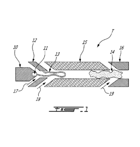
[0040] FIG. 1 is a cross-sectional side view of a plasma torch in
accordance with an exemplary embodiment, wherein a pilot arc between a button
cathode and a pilot insert is illustrated as well as a hot plasma gas
channeled in a
long tubular insert;
[0041] FIG. 2 is another cross-sectional side view of the plasma
torch,
showing a main arc between the button cathode and an anode;
[0042] FIG. 3 is a schematic illustration of an electrical
arrangement, and a
cross-sectional side view of the plasma torch, in accordance with an exemplary
embodiment, which allows the operation of the torch in energizing the pilot
arc by
closing first and second switches; upon transfer of the arc to the anode, such
as
SUBSTITUTE SHEET (RULE 26)
CA 02948681 2016-11-10
WO 2015/172237
PCT/CA2015/000325
7
illustrated in FIG. 2, the second switch may be opened;
[0043] FIG. 4 is a schematic partial sectional view of the relevant
parts of
a first embodiment of the long tubular insert in accordance with an exemplary
embodiment;
[0044] FIG. 5 is a schematic partial sectional view of the relevant
parts of
a second embodiment of the long tubular insert in accordance with an exemplary
embodiment; and
[0045] FIG. 6 is a schematic partial sectional view of the relevant
parts of
a third embodiment of the long tubular insert in accordance with an exemplary
embodiment.
DESCRIPTION OF VARIOUS EMBODIMENTS
[0046] The present apparatus is intended to address at least some of
the
disadvantages, discussed above, of previous gas heaters, mainly, to have to
choose
between an energy efficient torch, operating at high current, with very high
maintenance costs and a torch, operating at high voltage, with low maintenance
costs but very poor energy efficiency.
[0047] Thus, by means of the present apparatus, it is possible for a
high
power arc plasma gas heater torch, operating at low current and high voltage
with a
long arc, to have both high energy transfer efficiency to the gas and low
maintenance
costs.
[0048] To this effect, an energy-efficient high power plasma torch of
the
SUBSTITUTE SHEET (RULE 26)
CA 02948681 2016-11-10
WO 2015/172237
PCT/CA2015/000325
8
type comprising:
[0049] a) a button cathode, for instance made of copper and water
cooled
and equipped with an insert made of Tungsten or Tungsten doped with, for
example,
Thorium, Zircon or Lanthanum, to emit the electrons required for the arc or
equipped
with an Hafnium insert to avoid having to operate with an inert pilot gas as
it would be
the case with the Tungsten or Tungsten doped insert,
[0050] b) a short tubular pilot insert, for instance made of copper
and
water cooled and mounted coaxially with the button cathode and used as a
temporary anode for the pilot arc established following breakdown between the
cathode and the pilot insert,
[0051] c) a long tubular insert, for instance made of an electrically
and
thermally insulating material and mounted coaxially with both the cathode and
the
pilot insert and used, at first, to channel the hot plasma gas generated by
the pilot arc
established between the cathode and the pilot insert, and, in operation, to
lengthen
the arc to obtain the required arc voltage,
[0052] d) a short tubular electrode, for instance made of copper and
water
cooled and mounted coaxially with the cathode, pilot insert and long insert
assembly
and used as the anode for the main arc established between the button cathode
and
that electrode, following the voltage breakdown in the hot plasma gas
generated by
the pilot discharge between the cathode and the pilot insert and channeled by
the
long tubular insert,
[0053] can be operated at high voltage and low current with a high
energy
efficiency of transfer of energy to the gas as the use of an arc extender
comprising an
insulating material limits greatly the heat loss to the cooling water.
SUBSTITUTE SHEET (RULE 26)
CA 02948681 2016-11-10
WO 2015/172237
PCT/CA2015/000325
9
[0054] Therefore, a plasma torch T such as illustrated in the
drawings,
adapted only for operation in the non-transfer mode, embodies the features of
the
present exemplary embodiment. The torch T comprises an outer body (not shown)
for instance made of metal such as stainless steel, in which the four
components
shown in the drawings, namely a cathode 10, a pilot insert 12, a long tubular
insert
15 and an anode 16, are enclosed.
[0055] The cathode 10 is of the button type, for instance made of
copper
and water cooled and it is equipped with an insert 11, for instance made of
Tungsten
or of Tungsten doped with, for example, Thorium, Zircon or Lanthanum to emit
the
electrons required for the arc, or equipped with an Hafnium insert to avoid
having to
operate with an inert pilot gas as it would be the case with the Tungsten or
Tungsten
doped insert.
[0056] As illustrated in FIG. 1, the pilot insert 12, also for
instance made of
copper and water cooled, is mounted coaxially with the cathode 10. The pilot
insert
12 is used, during start-up, as a temporary anode for a pilot arc 13
established
following electrical breakdown between the cathode 10 and the pilot insert 12.
[0057] Also, as illustrated in FIG.1, the long tubular insert 15, for
instance
made of an electrically and thermally insulating material and mounted
coaxially with
both the cathode 10 and the pilot insert 12, is used, during start-up, to
channel hot
plasma gas 14 generated by the pilot arc 13 established between the cathode 10
and
the pilot insert 12. The length of the long tubular insert 15 depends, at
least in part,
on the desired operating voltage and arc length.
[0058] FIG. 2 illustrates the normal torch operation with a main arc
20
established between the cathode 10 and the downstream anode 16. The long
insert
15 is now used to bring into contact with the arc 20, the gases 17 and 18,
injected
SUBSTITUTE SHEET (RULE 26)
CA 02948681 2016-11-10
WO 2015/172237
PCT/CA2015/000325
into the torch T by vortex generators (not shown) located between the cathode
10
and the pilot insert 12 and between the pilot insert 12 and the long insert
15,
respectively. Additional gas 19 is injected by a third vortex generator (not
shown)
located between the long insert 15 and the anode 16.
[0059] The gas 19 is injected tangentially with respect to the anode
surface, primarily, in order to force the arc attachment point to move rapidly
on the
anode surface in a circular motion as to distribute evenly the erosion of
metal from
the electrode to extend the torch operation length of time between required
maintenance. A magnetic coil or a permanent magnet can also be provided around
the anode 16 in order to apply an electromagnetic force on the arc to move the
arc
attachment point even faster on the anode surface and thus to reduce the
electrode
erosion even more.
[0060] An electrical arrangement E is illustrated in FIG. 3. To
proceed with
the start-up, first and second switches 21 and 23 are both closed and a DC
power
supply 24 is turned on. An ignition module (not shown), connected between the
cathode 10 and the pilot insert 12, is used to ionize the pilot gas between
the cathode
and the pilot insert resulting in the establishment of the pilot arc 13 which,
as shown
in FIG. 3, is supported by the DC power supply 24.
[0061] As shown in FIG. 1, the pilot arc 13, driven by the vortex
flows 17
and 18, generated by gas vortex generators (not shown), extends somewhat in
the
tubular passage of the long insert 15. In addition, ionized gases produced by
the
pilot arc 13 lower considerably the electrical resistance path between the
anode 16
and the downstream extension of the pilot arc 13. A resistor 22 is used to
further
increase the voltage difference between the anode 16 and the pilot insert 12.
Because of this higher voltage potential of anode 16, an electrical breakdown
between the extended arc 13 and the anode 16 should occur well before the arc
13
SUBSTITUTE SHEET (RULE 26)
CA 02948681 2016-11-10
WO 2015/172237
PCT/CA2015/000325
11
has reached the anode 16. Upon initiation of the main arc 20, the second
switch 23 is
disengaged.
[0062] As illustrated in FIGS. 1, 2 and 3, the internal diameter of
the pilot
insert 12 is smaller than that of the long tubular insert 15. It has been
found, during
tests, that the ratio between the diameter of the pilot insert 12, dl, and
that of the
long tubular insert 15, d2, affects the arc stability; in one embodiment,
preliminary
tests have used, for a power up to 400 kW, a ratio of d2 / dl in the 1.15 to
1.35
range.
[0063] In FIGS. 4, 5 and 6, there are shown further embodiments of the
apparatus in accordance with exemplary embodiments, whereby only the most
relevant parts of the long tubular insert are shown. In each of these
embodiments,
the long tubular insert, for instance made of mostly insulating material, is
contained
into a tubular arrangement made mostly of metal which is water cooled.
[0064] In the embodiment of FIG. 4, the internal insert 15 is made of
one
piece inserted in a tubular arrangement that includes metal rings 31 sealed
and
insulated from one another by sealing rings 32.
[0065] In the embodiment of FIG. 5, the internal insert includes rings
33 of
insulating material, separated by metal rings 34 which are, themselves, sealed
and
insulated from one another by sealing rings 35.
[0066] In the embodiment of FIG. 6, the internal insert also includes
rings
36 of insulating material, different in cross section from those shown in FIG.
5. The
rings 36 are separated by metal rings 37 which are, themselves, sealed and
insulated
from one another by sealing rings 38.
SUBSTITUTE SHEET (RULE 26)
CA 02948681 2016-11-10
WO 2015/172237
PCT/CA2015/000325
12
[0067] In FIGS. 5 and 6, the number of rings of insulating material 33
and
36 respectively, will depend, at least in part, on the desired operating
voltage and arc
length.
[0068] The long tubular insert comprising either a single long tube 15
(as
shown in FIGS. 1 to 4) or of a number of rings 33 and 36 (as shown in FIGS. 5
and 6,
respectively) is for instance made of a material having a good electrical
resistivity and
low thermal conductivity and simultaneously having a very high melting
temperature
such as, for example, Silicon Carbide or Hexoloy manufactured by Saint-Gobain
Ceramics, or Boron Nitride also manufactured by Saint-Gobain and by ESK.
Silicon
Carbide, Hexoloy and Boron Nitride are considered, for example, because their
thermal conductivity being about five times lower than copper, the heat loss
from the
hot plasma channeled into the long insert between the cathode and the anode
will be
only about 20% of what it would be with copper.
[0069] Although not shown in the drawings, the long tubular insert
that
includes either a single long tube 15, as shown in FIGS. 1, 2, 3 and 4, or of
a number
of rings 33 and 36, as shown respectively in FIGS. 5 and 6, is provided with
orifices
in the wall(s) thereof, at different locations, to inject a gas tangentially.
The resulting
vortex gas flows increase the heat transfer from the arc to the surrounding
gas and in
that way increase the voltage required to sustain the arc. These additional
vortex
flows, in the long tubular insert, not only cool the insert bore surface but
also stabilize
the arc and allow increasing the insert bore diameter, wall stabilization
being less
required.
[0070] The exemplary embodiment is further illustrated by the
following
example:
[0071] EXAMPLE
SUBSTITUTE SHEET (RULE 26)
CA 02948681 2016-11-10
WO 2015/172237
PCT/CA2015/000325
13
[0072] For comparison, tests were conducted with a plasma torch
equipped with either a long tubular copper anode or with the insulating insert
as
described in relation with FIG. 1.
[0073] In both case the power was 400 kW at 800 Amperes and 500 Volts.
Air flow was 920 liters per minute. The cathode and nozzle water cooling
circuit was
independent from the anode water cooling circuit in order to be able to make
separate measurements of the heat loss of these torch components.
[0074] Water flows to the cathode and the anode were 45 liters per
minute
and 40 liters per minute, respectively. The cathode water temperature increase
was
8 C in both cases indicating a heat transfer to the cooling water of 25 kW.
[0075] With the long tubular copper anode the water temperature
increase was 25 C corresponding to a heat transfer to the cooling water of
69.7 kW.
[0076] When equipped with the insulating insert the anode temperature
increase was only 5 C corresponding to a heat transfer of 14 kW.
[0077] The corresponding torch efficiencies were 76% for the torch
equipped with a regular copper anode and 90% for the torch equipped with the
insulating insert, therefore an increase of 14% in efficiency.
[0078] While the above description provides examples of the
embodiments, it will be appreciated that some features and/or functions of the
described embodiments are susceptible to modification without departing from
the
spirit and principles of operation of the described embodiments. Accordingly,
what
has been described above has been intended to be illustrative of the
embodiments
SUBSTITUTE SHEET (RULE 26)
CA 02948681 2016-11-10
WO 2015/172237
PCT/CA2015/000325
14
and non-limiting, and it will be understood by persons skilled in the art that
other
variants and modifications may be made without departing from the scope of the
embodiments as defined in the claims appended hereto.
[0079] References:
- US Patent Documents:
o 4,543,470 9/1985 Santen, et al
o 5,132,511 6/1992 Labrot, et al
- Other Publications:
o Ramakrishnan, et al, Technological Challenges in Thermal Plasma,
CSIRO Publishing www.publish.csiro.au/?act=view file&file id=
PH950377
o Camacho, Industrial-worthy plasma torches State-of-the-art, Pure &
AppL Chem., Vol. 60, No. 5, pp. 619-632, 1988.
o Mogensen, et al, Electrical and Mechanical Technology of Plasma
Generation and Control, in Plasma Technology in Metallurgical
Processing by J. Feinman, The Iron and Steel Society, 1987, pp. 65-76
o Eschenbach, et al, Plasma Torches and Plasma torch Furnaces, in
Plasma Technology in Metallurgical Processing by J. Feinman, The Iron
and Steel Society, 1987, pp. 77-87.
o Hanus, Phoenix Solutions' Plasma Arc Application and High-
Temperature Process Experience, Proceedings Plasma Arc
Technology, October 29-30, 1996, pp. 321-352.
SUBSTITUTE SHEET (RULE 26)