Note: Descriptions are shown in the official language in which they were submitted.
CA 02948766 2016-11-10
WO 2015/177683
PCT/IB2015/053488
1
"Process for producing a package for a foodstuff
product, in particular a confectionery product"
****
Field of the invention
The present invention relates to a process for
producing a package for foodstuff product, in
particular a confectionery product, comprising the
steps of:
- providing a first sheet of wrapping material,
which presents a first portion for receiving said
product and a first peripheral portion surrounding said
first receiving portion;
- providing a second sheet of wrapping material
which presents a second portion for receiving said
product and a second peripheral portion surrounding
said second receiving portion;
- setting said product on said first receiving
portion or said second receiving portion;
- coupling said first sheet to said second sheet
in such a way that said first and second portions for
receiving said product will define together a closed
cavity in which said product is housed, and in such a
way that said first and second peripheral portions are
set in contact with one another so as to form a flange
surrounding said cavity; and
- folding said flange along a folding line such as
to define a proximal flange part and a distal flange
part connected to said proximal part by said folding
line, said distal part being folded back towards said
cavity, against said proximal part, along said folding
line.
General technical problem
A process of the type referred to above is known
from the European patent No. EP2366631 B1 filed in the
name of the present applicant.
CA 02948766 2016-11-10
WO 2015/177683
PCT/IB2015/053488
2
The above type of process is frequently used for
packaging confectionery products, typically chocolate-
based ones, the outer surface of which has a particular
shape, representing, for example, fantasy human or
animal characters, or again objects linked to
traditions of festivals, such as Christmas bells or
Easter eggs, in order to produce packages that
reproduce on the outside exactly the particular shape
thereof. For this purpose, the two sheets of wrapping
material of the package are made to adhere to the
entire outer surface of the product.
In the above type of package, the aesthetic
appearance evidently has the same importance as the
protection that it ensures for the product.
In this connection, precisely in order to enhance
the aesthetic appearance of the package, usually the
folded flange mentioned at the start is obtained so as
to identify as a whole a profile substantially
corresponding to the external contour of the packaged
product so that the product is as if it were framed.
The patent indicated above describes in detail how
to obtain the aforesaid folded flange. In this
connection, it should be noted that the flange in
question has in any case evidently the main function of
holding together the two sheets of the wrapper.
The present applicant has, however, noted that
packages of the type in question may at times be
present on the shelves of sales outlets partially open,
with the peripheral portions of the two sheets locally
detached. This is due to the fact that, during handling
and transport of the packages, the flange can
accidentally unfold in one or more parts, and at that
point, given that the corresponding peripheral portions
of the two sheets are no longer constrained together,
they start to separate, thus rendering the inside of
3
the packages accessible.
Clearly, this possibility constitutes a problem
both from an aesthetic standpoint, because the
partially open package has in any case lost its
pristine appearance, and obviously from a safety
standpoint, in so far as the package can no longer
perform its protective function in a complete way.
Object and summary of the invention
The present invention falls within the above
context and its object is to provide a process of the
type indicated at the start that will enable a package
to be obtained that is less subject to the aforesaid
drawbacks.
The aforementioned object is achieved via a
process as described herein. The present invention
moreover regards a package obtained via the process in
question, and a device for implementing the sealing
step envisaged in said process.
Brief description of the drawings
The invention will now be described purely by way
of non-limiting example, with reference to the annexed
representations, wherein:
- Figure 1 is a perspective view of a package
obtained according to the process described herein;
- Figure 1A illustrates a top plan view of the
package of Figure 1;
- Figure 1B illustrates a detail of the package of
Figure 1 in a cross-sectional view according to the
line A-A of Figure 1A;
- Figures 2 to 22 are schematic representations
that illustrate successive steps of the process
described herein in a preferred embodiment;
WSLEGAL\068915 \00011\29653055v1
Date Recue/Date Received 2022-02-03
CA 02948766 2016-11-10
WO 2015/177683
PCT/IB2015/053488
4
- Figure 23 is a perspective view of a crimping
tool used in the framework of the process; and
- Figure 24 is a top plan view of the tool of
Figure 23, shown in an operating position thereof
together with the article on which the tool operates
for carrying out the crimping operation.
Detailed description of the invention
In the ensuing description, various specific
details are illustrated aimed at providing an in-depth
understanding of the embodiments. The embodiments may
be obtained without one or more of the specific
details, or with other methods, components, or
materials, etc. In other cases, known structures,
materials, or operations are not shown or described in
detail so that the various aspects of the embodiment
will not be obscured.
The references used herein are only provided for
convenience and hence do not define the sphere of
protection or the scope of the embodiments.
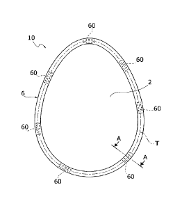
Figure 1 illustrates an example of package for a
product P, in the specific case an Easter egg, obtained
according to the process described herein.
In general, the above type of package, designated
in Figure 1 by the reference number 10, comprises a
first sheet of wrapping material 2 and a second sheet
of wrapping material 4 coupled together.
The sheet 2 has a portion for receiving the
product 2a and a peripheral portion 2b that surrounds
the receiving portion 2a. Likewise, the sheet 4 has a
portion for receiving the product 4a and a peripheral
portion 4b that surrounds the receiving portion 4a.
The sheets 2 and 4 are coupled together in such a
way that the receiving portions 2a, 4a will define
together a closed cavity C in which the product P is
housed, and in such a way that the peripheral portions
CA 02948766 2016-11-10
W02015/177683
PCT/IB2015/053488
2b, 4b are set in contact with one another so as to
form a flange 6 surrounding the cavity C (see Figure
1A).
The flange 6 is folded on itself so as to identify
5 a proximal part 6a and a distal part 6b joined together
along a folding line "s". The distal part 6b is folded
back towards the cavity C, against the proximal part
6a, along the line "s". It should be noted that Figure
1B is an enlarged representation that does not respect
the real proportions of the various elements, provided
to enable an immediate understanding of the structure
of the flange 6. In this figure the folding line "s" is
constituted by a perimetral band. However, in the real
package the thicknesses of the sheets 2 and 4 have
dimensions that are so small, compared to the structure
of the package, that the band can actually be
approximated by a line, namely, a folding line.
In various embodiments, as in the one illustrated,
the portions for receiving the product 2a and 4a, which
together identify the cavity C, each reproduce the
conformation of the outer surface of the corresponding
part of the product P so as adhere substantially to the
product. This configuration enables the package to
reproduce, substantially identically, the shape of the
product contained therein. The receiving portions 2a
and 4a may hence be of any shape that depends only upon
the shape of the packaged product, and may consequently
also differ from one another, for example in the cases
where the product has different opposite faces. In this
connection, there may also be embodiments in which the
receiving portions 2a and 4a do not both have a generic
half-shell shape as in the example illustrated, but,
instead, one of them is completely plane.
In various embodiments, as in the one illustrated,
the line of connection of the sheets 1 and 2 inside
CA 02948766 2016-11-10
WO 2015/177683
PCT/IB2015/053488
6
the cavity C is, throughout its extension or at least
part thereof, directly in contact with the product P,
and the folding line "s" of the flange 6 extends
parallel thereto, so that as a whole the flange
reproduces almost exactly the profile that the product
P has in the plane of the flange. The aesthetic result
is that of a greater enhancement of the global shape of
the product.
In order to produce a package of the type
described above the process in question envisages in
general the steps of:
- providing a first sheet of wrapping material,
which presents a first portion for receiving said
product and a first peripheral portion surrounding said
first receiving portion;
- providing a second sheet of wrapping material,
which presents a second portion for receiving said
product and a second peripheral portion surrounding
said second receiving portion;
- setting said product on said first receiving
portion or said second receiving portion;
- coupling said first sheet to said second sheet
in such a way that said first and second portions for
receiving said product will define together a closed
cavity in which said product is housed, and in such a
way that said first and second peripheral portions are
set in contact with one another so as to form a flange
surrounding said cavity; and
- folding said flange along a folding line such as
to define a proximal flange part and a distal flange
part connected to said proximal part along said folding
line, said distal part being folded back towards said
cavity, against said proximal part, along said folding
line.
The process described herein is characterized in
CA 02948766 2016-11-10
WO 2015/177683
PCT/IB2015/053488
7
that it envisages forming on said flange a plurality of
sealing areas 60, distinct and separate from one
another, designed to keep the aforesaid first and
second sheets together, and in that the sealing areas
are obtained at at least a minimum distance from the
aforesaid first receiving portion and/or second
receiving portion. In various preferred embodiments,
the aforesaid minimum distance is such that the sealing
areas are located, after the folding step, in the
distal part of the folded flange, and are not traversed
by the folding line. In alternative embodiments, the
aforesaid minimum distance is, instead, such that,
after the folding step, the sealing areas are in any
case traversed by the folding line.
It should be noted that by the expression "sealing
area" is here to be understood any region of the two
sheets 1 and 2 at which they are joined together as a
result, for example, of a sealing operation, a gluing
operation, or any other operation that has the effect
of getting the two sheets to adhere together in a
permanent way.
In various embodiments, as in the one illustrated,
the aforesaid sealing areas are set in succession along
a closed path - designated in Figure lA by the
reference T - that surrounds the first and second
receiving portions 2a, 4a. In various preferred
embodiments, each sealing area has, in a direction
substantially orthogonal to the corresponding stretch
of the aforesaid closed path, a dimension preferably
smaller than or equal to the width of the distal part
6b of the folded flange 6. In various even more
preferred embodiments, this dimension constitutes the
minimum dimension of the above area. The areas 60 have
a preferably rectangular shape but may even have any
other shape, and may all be the same as one another, or
CA 02948766 2016-11-10
WO 2015/177683
PCT/IB2015/053488
8
else the same in subsets, or, again, all different from
one another.
As has been said, the sealing areas in question
have the function of holding together the two sheets
that make up the package in such a way that these do
not separate from one another. This overcomes the
drawbacks described at the start regarding traditional
packages, since, in the case where the folded flange 6
opens locally or completely, the sheets 1 and 2 in any
case remain constrained together in the areas 60. In
this connection, the maximum distance between two
consecutive areas 60 may be chosen in such a way that
the sheets 1 and 2 will remain in any case in contact
along the portions 2b and 4b between the two areas,
even in the absence of the folded flange, as a result
of the internal stresses determined by the presence of
the two contiguous areas 60. In various preferred
embodiments, the distance in question is smaller than
or equal to 50 mm, according to the perimeter of the
flange and the size of the product. The sealing
obtained is not, instead, such as to close the package
hermetically.
The characteristic indicated above, inherent in
provision of the sealing areas 60 at the aforesaid
minimum distance from the receiving portions 2a, 2b,
evidently entails, in its preferred embodiment, that
the subsequent folding step will involve directly -
subjecting them to deformation - only non-sealed
portions of the flange 6, and not, instead, also the
sealing areas themselves. This makes it possible to
obtain a perfectly folded flange, which remains stably
in this condition, without the risk of any elastic
return towards an unfolded condition. In this
connection, the present applicant has in fact noted
that the above phenomena of elastic return occurs when
CA 02948766 2016-11-10
WO 2015/177683
PCT/IB2015/053488
9
the folding step involves, instead, also or only the
sealing areas, i.e., in the cases where these are
traversed by the folding line "s". The reason for this
behaviour is to be attributed to the fact that, where
the sheets 2 and 4 are sealed together, the flange 6 is
as a whole more rigid, and consequently assumes a
mechanical behaviour substantially more elastic than
the remaining parts.
The characteristic indicated above is moreover
advantageous in the cases where the areas 60 are
obtained via a proper welding process, in so far as it
prevents the heat necessary for sealing the two sheets
from causing at the same time melting or in any case a
variation of consistency of the product P. Providing
the sealing areas at a distance from the portions for
receiving the product presupposes, in fact, that the
sealing means themselves are located at a distance from
these portions (which already in itself reduces the
amount of heat coming from the sealing means that
reaches the product). In the space provided between
these and the product, it is then possible to insert
means for protecting the product P from the heat
generated during sealing.
Finally, it should be noted that positioning of
the sealing areas 60 on the distal portion 6b of the
folded flange 6 guarantees that the end edges of the
two sheets 1 and 2 are perfectly coincident, i.e.,
aligned - thus preventing the internal sides of the two
sheets from remaining in view - and that the portions
2b, 4b are laid out perfectly on top of one another
without forming any creases.
In view of what has been said above, it is hence
evident how the characteristics of the process
described herein enable the drawbacks of the known art
linked to accidental opening of the packages to be
CA 02948766 2016-11-10
WO 2015/177683
PCT/1B2015/053488
overcome, at the same time also guaranteeing optimal
aesthetic finish of the packages themselves.
The packaging process will now be described in
detail, in its different possible embodiments. For this
5 purpose, reference will be made to Figures 2 to 25,
which are schematic illustrations having merely the
purpose of enabling an immediate understanding of the
main aspects of the process and of the means used to
implement it. In particular, in what follows reference
10 will be made to production of a single package, but it
is clear that the same means described may be easily
configured for producing simultaneously a number of
packages at the same time.
The process envisages in the first place providing
the first and second sheets of wrapping material 2 and
4 that will constitute the package. The sheets 2 and 4
are preferably made of a plastically deformable
material, typically aluminium, of a thickness of from
10 m to 40 m, and are coated with a layer of heat-
meltable or heal-sealable material, for example
polyethylene or any other plastic material of a similar
type, or else are coated with a heat-sealing lacquer.
In various embodiments, as in the one illustrated,
the process envisages shaping the first and second
sheets so as to define on them the portions 2a and 4a
for receiving the product shown in Figure 1B.
In various embodiments, as in the one illustrated,
for this purpose the process envisages use of moulds 8'
and 8", which have respective mould cavities 9 and 11
of a shape corresponding to complementary portions of
the outer surface of the product to be packaged. The
sheets 2 and 4 are set on the moulds 8' and 8", and for
example with the aid of a pad 10, having a shape
complementary to the surface of the mould cavity, are
subjected to a drawing operation through which formed
CA 02948766 2016-11-10
WO 2015/177683
PCT/1B2015/053488
11
on the sheets 2 and 4 are the parts 2a and 4a for
receiving the product, surrounded respectively by the
peripheral portions 2b and 4b, of a substantially plane
conformation.
In various embodiments, as in the one illustrated,
the shaped sheets 2 and 4 are then transferred into the
auxiliary supports 12 and 14, which have respective
seats 16 and 18, for receiving the shaped parts 2a and
4a, and respective plane surfaces 20 and 22, which
surround the seats 16 and 18 and are designed to
support the flange portions 2b and 4b. In various
embodiments, as in the one illustrated, one of the
above supports, the support 12 in the example
illustrated, has an annular slit or groove 24 (see
Figure 5) surrounding the seat 16 of the support, the
function of which will be described in what follows.
In various embodiments, as in the one illustrated,
the supports 12 and 14 can be moved with respect to one
another between an open condition, for example
illustrated in Figure 4, and a closed condition, for
example illustrated in Figure 7, and moreover, in the
latter condition, be rotated together, about an axis
orthogonal to the plane of the figures. The means for
obtaining these movements of the supports 12 and 14 may
be of any type already known to the person skilled in
the sector and consequently will not be described in
detail herein.
In the condition illustrated in Figure 5, the
article P is positioned, with transfer means in
themselves known, for example of the suction-pad type,
in the receiving part 4a of the sheet 4, and, then, by
turning over the support 12 through 1800 onto the
support 14 (Figures 6 and 7), the sheet 2 is coupled to
the sheet 4 in a position overlying the surface portion
of the article P that emerges from the seat 18. A
CA 02948766 2016-11-10
WO 2015/177683
PCT/IB2015/053488
12
configuration is thus obtained in which the two sheets
2 and 4 are set with their peripheral portions 2b and
4b in contact with one another to form the flange 6,
and with their receiving portions 2a and 4a that
together define the cavity C containing the product P.
Next, the supports 12 and 14 are brought into their
open condition as illustrated in Figure 8.
The process described herein envisages at this
point providing the sealing areas 60, in order to join
the sheets 2 and 4 together.
As has been said previously, the process described
herein is characterized in providing the various
sealing areas 60 at a given distance from the receiving
portions of the two sheets of wrapping material that is
greater than or equal to a minimum distance.
Preferably, this is selected in such a way that, after
the folding step, the sealing areas come to be located
on the distal part of the folded flange 6, and are not
traversed by the folding line defined therein. This
value is hence a function of the width of the proximal
part of the folded flange and, in general, with respect
to said width, may be the same or greater. The width of
the areas 60 themselves - measured for each area in a
direction transverse to the corresponding stretch of
the aforesaid closed path T - evidently cannot be,
instead, greater than the width of the distal part of
the folded flange.
In various embodiments, as in the one illustrated,
in order to obtain the areas 60 the process described
herein envisages the use of a sealing device 52.
This device in general comprises supporting means
configured for receiving the sheets 2 and 4 coupled
together, which identify a seat on which the receiving
portion 2a or 4a of the above sheets is to be set, and
a contrast surface, preferably plane, on which the
CA 02948766 2016-11-10
WO 2015/177683
PCT/IB2015/053488
13
peripheral portions 2b, 4b is to be set. The device 52
further comprises a pressure element 54 having a series
of heating sections 54a corresponding in number and
shape to the series of the areas 60 to be obtained on
the flange 6. The element 54 is actuated by motor means
53 for pressing with the sections 54a the parts 2b, 4b
against the aforesaid contrast surface. In various
embodiments, as in the one illustrated, these
supporting means are constituted by one of the supports
12 and 14 themselves, in this case the aforesaid seat
being constituted by the seats 16 and 18 of the above
supports, whereas the aforesaid contrast surface is
constituted by their surfaces 20, 22. In alternative
embodiments, the supporting means in question are,
instead, constituted by a support that is altogether
similar to the supports 12 and 14 but is exclusively
designed for use with the sealing device 52. In various
preferred embodiments, optionally set on the aforesaid
contrast surface is an elastic element 44, for example
made of silicone, against which the parts 2b, 4b are
pressed. The element 44 has the function of
compensating, as a result of its elastic consistency,
any possible imperfections of the contrast surface
and/or of the sections 54a. In various embodiments, as
in the one illustrated, the elastic element 44 is
received in a corresponding groove obtained in the
contrast surface 22.
In the region where the portions 2b, 4b are
pressed by the sections 54a, they are sealed together,
as a result of the combined action of pressure and heat
exerted by the above sections. As has been said, in
order to obtain the sealing areas 60, the sections 54a
are in a number corresponding to the number of the
areas 60 and moreover have a corresponding shape. In
particular, the plurality of sections 54a extend along
CA 02948766 2016-11-10
WO 2015/177683
PCT/IB2015/053488
14
a closed path such that, in the operative condition of
the element 54, they arrange themselves around the
receiving portions 2a, 4a, remaining at a distance
equal at least to the aforesaid minimum distance of the
areas 60, designated by H in Figure 9A.
As may be seen in Figures 9 and 9A, in the
aforesaid operative position of the element 54, between
the heating sections 54a and the shaped part 4a a free
space is provided. In various embodiments, as in the
one illustrated, the process envisages inserting in
this space means designed to protect the product P from
the heat transmitted by the heating sections.
In this connection, in various embodiments, as in
the one illustrated, the device 52 preferably comprises
a cooling body 56, set within the element 54 and
configured for covering the shaped part 4a of the
package and the portion of product contained therein,
preventing direct exposure thereof to the heating
sections and absorbing the heat transmitted by them.
The body 56 has in particular a cavity 56a, designed to
receive the shaped part 4a, and an edge 56b, which
surrounds the cavity and has a width such that it can
be inserted in the space between the sections 54a and
the shaped part 4a.
The device 52 further comprises means for
circulation of a cooling fluid (not illustrated) within
the body 56. In particular, the body 56 comprises one
or more ducts that are set around the cavity 56a and
are associated to supply means designed to cause
circulation in these ducts of the cooling fluid. During
operation of the device, the cooling fluid absorbs the
heat emitted by the heating sections 54a, thus
preventing it from heating the portion 4a and the
product P.
The body 56 can be carried by the pressure element
CA 02948766 2016-11-10
WO 2015/177683
PCT/IB2015/053488
54 itself, or else by a separate movement structure,
actuation of which is co-ordinated with the element 54.
In alternative embodiments, instead of the cooling
body 56 it is possible to envisage simply a body made
5 of insulating material designed to prevent transfer of
heat to the product P.
It should be noted that the protection means
described above are optional and, according to the
applications, they could even be absent, taking amongst
10 other things into account that the sealing areas 60 are
precisely at a given distance from the product and
extend locally for limited stretches and not all around
the product itself so that the amount of heat that
reaches the product is in any case limited. In
15 different embodiments, the distance H between the
heating sections 54a and the product P may hence be
sufficient to prevent damage to the product due to the
heat emitted by the above sections.
The means described above may, instead, become
necessary for very delicate articles and/or for very
small packages in which sealing is in any case
performed very close to the product.
The sealing device 52 described above may
constitute a station within a packaging plant, which
carries out on line one or more of the operations
previously described, or else may constitute a stand-
alone device, supplied to which by the line of the
plant are the products P with the corresponding sheets
2 and 4 associated thereto.
At the end of the sealing operation, the sheets 2
and 4 are joined together.
After the sealing step, the process described
herein finally envisages providing the folded flange of
the package.
In general, this step envisages folding the flange
CA 02948766 2016-11-10
W02015/177683
PCT/IB2015/053488
16
6 on itself, along the folding line "s", so as to
identify the proximal part 6a and the distal part 6b.
Along the folding line "s", the distal part 6b is
folded back towards the cavity C, so that it is brought
up against the proximal part 6a. As a result of what
has been said previously, the operation of folding of
the flange 6 does not subject the sealing areas 60 to
deformation, and, once completed, causes these areas to
be located in a position corresponding to the distal
part 6b (see Figures 1A and 15 to 23).
Optionally, prior to the folding operation
described above, a cutting operation is provided to
reduce the flange 6 to the desired width.
In various embodiments, as in the one illustrated,
the cutting and folding operations indicated above are
carried out using the methods and devices according to
the patent No. EP2366631 cited at the start, which will
also be described herein in detail in what follows for
completeness of treatment. It is clear, however, that
the operations in question can be obtained also using
alternative methods and/or devices. It should be noted
in this connection that the advantages discussed above
linked to the positioning of the sealing areas at a
distance from the product P are clearly achieved also
in the case of use of methods and/or devices different
from those described in what follows.
In various embodiments, as in the one illustrated,
starting from the condition represented in Figure 11,
the wrapping obtained by the sealing operation is
transferred from the support 14 to the support 12. For
this purpose, a movement of the supports 12 and 14 is
carried out comprising in succession i) turning over
the support 12 through 1800 onto the support 14 (Figure
11), ii) turning over through 180 the ensemble formed
by the supports 12 and 14 coupled together (Figure 12),
CA 02948766 2016-11-10
WO 2015/177683
PCT/IB2015/053488
17
in such a way that the product and the wrapping will
pass from a condition where they are carried by the
support 14 to a condition where they are carried by the
support 12, and finally iii) removing the support 14
from the support 12 (Figure 13).
In various embodiments, as in the one illustrated,
the process then envisages an operation of cutting of
the flange 6, aimed at obtaining the desired width of
the above flange.
This cutting operation is preferably carried out
causing, simultaneously with cutting, folding of a
distal portion of the flange in a condition set at an
angle, preferably orthogonal, with respect to the
remaining proximal portion, so as to identify already
in this step the aforesaid proximal and distal parts 6a
and 6b that will come to form the folded flange in the
next process step.
In various embodiments, as in the one illustrated,
the above operation can be carried out by means of a
device of the type illustrated in Figure 14, which co-
operates with the support 12, provided with the annular
groove 24. This cutting device comprises a vertically
mobile support 26, associated to which are an annular
cutting or dinking member 28 and pressure means 30, 32,
preferably elastically constrained to the support 26,
which surround internally and externally the annular
cutting member 28. The cutting device is positioned
with the pressure means 30, 32 in contact with the
flange 6, and with the cutting member 28 designed to
penetrate into the groove 24. The cutting end 28a of
the cutting member 28 is able to penetrate into the
groove 24 at a slight radial distance from the radially
internal wall 24a of the groove 24, this distance being
sized so as to be able to receive the folded flange
part.
CA 02948766 2016-11-10
WO 2015/177683
PCT/IB2015/053488
18
In this way, during the cutting operation, the
pressure means 30, 32 constrain the flange 6, and
lowering of the cutting member inside the groove 24
causes, simultaneously with cutting of the peripheral
portions of the flange, folding downwards of the distal
portion 6b with respect to the proximal portion 6a. The
offcuts, designated as a whole by 13, can be removed
after the cutting operation, for example by suction in
a subsequent process step.
Next, the process preferably contemplates an
operation of turning the wrapping material over through
180 , so as to position the folded flange parts
upwards. This operation can for example be carried out
according to the operating steps of Figures 16, 17, 18,
and 19, which comprise turning the support 14 over onto
the support 12 to obtain the configuration of Figure
17, in which the wrapping material is closed between
the supports 12 and 14, turning the two associated
supports 12, 14 over through 1800 (Figure 18), and
subsequently opening the top support 14 to obtain the
configuration of Figure 19.
Then the process envisages that the distal part 6b
of the flange will be folded back against the
corresponding proximal part 6a.
In various embodiments, as in the one illustrated,
in order to carry out the above operation the process
described herein envisages use of the crimping device
described in the European patent No. EP2366631. The
term "crimping", which in mechanical technologies is
used to indicate the operation of clinching the edge of
riveted metal sheets, is here used in a broad sense to
indicate an operation of deformation, folding, and/or
clinching of the flange 6.
This device may constitute a station that operates
in line within a packaging plant, or else may
CA 02948766 2016-11-10
WO 2015/177683
PCT/IB2015/053488
19
constitute a stand-alone device to which the wrappers
to be treated can be supplied by the line of the plant.
The device in question may be provided for co-
operating directly with one of the supports 12 or 14
described previously, or else, as an alternative, may
comprise its own means for supporting the wrapping
material, which, like the supports 12 and 14, in
general comprise a seat designed to support one of the
two shaped parts 4a or 2a of the wrapping, and a
substantially plane surface, which surrounds this seat
and is designed to support the flange 6.
The device in question comprises crimping means
provided for bringing about folding and/or clinching of
the distal part 6b with respect to the article P,
starting from a configuration of the type illustrated
in Figure 20, in which this part is already folded in
an angled position, generally practically orthogonal to
the surface 22 of the support 14.
The aforesaid crimping means comprise a crimping
tool, designated by 36, which may be a body in the form
of a plate provided with an opening 38 (Figure 23),
having a perimetral profile 40 homologous and enlarged
with respect to the perimetral profile defined by the
end of the flange 6.
The crimping tool 36 may thus be positioned in
contact with the surface 22 of the support 14, with the
opening in a position surrounding at a distance the
distal portion 6b, i.e., in the configuration of Figure
24, in which the receiving portion 2a is visible, the
perimetral profile defined by the distal portion 6b and
the profile 40 of the opening 38 that is positioned at
a practically uniform distance from the portions 6a,
6b.
The crimping tool is vertically mobile with
respect to the supporting means between a raised
CA 02948766 2016-11-10
WO 2015/177683
PCT/IB2015/053488
position and a lowered position, in which it is
practically in contact with the surface 22. The
crimping tool 36 is moreover mobile in a horizontal
plane. Motor means 42 (see Figure 20) are provided for
5 actuating the crimping tool for its vertical and
horizontal movement.
In particular, the motor means 42 are provided for
bringing consecutive or non-consecutive stretches of
the profile 40 of the opening 38 into contact with a
10 homologous stretch of the profile defined by the distal
portion 6b previously folded. This operation can be
carried out in the position in which the bottom end of
the crimping tool is in contact with the surface 22 and
is useful also for achieving, if need be, a correct
15 positioning of the distal portion 6b in the position
orthogonal to the surface 22 (Figure 20). Next, the
crimping tool is subjected to a vertical movement for a
distance d greater than the thickness of the flange 6
and such that the bottom end of the profile 40 and of
20 the opening 38 may still interfere, following upon a
horizontal displacement, with the top end of the distal
portion 6b (Figure 21).
Consecutively, the crimping tool 36 is subjected
to a horizontal movement of approach to the body of the
article P in such a way as to cause further folding
inwards of the distal portion 6b (Figure 22) over the
proximal portion 6a.
Optionally and in any case preferably, the
crimping tool 36 is then subjected to a vertical
movement of approach to the surface 22 of the support
14, in order to cause clinching (Figure 23).
The aforesaid operations, i.e., the operations of
Figures 20, 21, and 22 and optionally also the
operations of Figure 23 (and clinching operations) are
carried out for further consecutive or non-consecutive
CA 02948766 2016-11-10
WID2015A77683
PCT/IB2015/053488
21
stretches of the profile of the flange. For example,
when the article has a generally quadrangular profile,
the aforesaid operations are carried out for each side
defining the profile.
In various embodiments, as in the one illustrated,
to reach the consecutive or non-consecutive stretches
of the flange 6, the crimping tool is operated
according to a translational movement in two mutually
orthogonal directions. In the case of the egg-shaped
profile of the figures, the crimping tool can
alternatively be pre-arranged for a rotary and
eccentric movement in the horizontal plane so as to
reach one after another consecutive or non-consecutive
stretches of the profile 40 of the opening 38 in
contact with the corresponding portions of the flange
6.
It should be noted that carrying out the crimping
operation along the entire flange profile does not
constitute an essential and imperative aspect of the
process, in so far as, in given applications, it may be
desirable to keep a portion of the flange profile not
crimped, i.e., to keep a stretch of the flange profile
not folded on itself. The process according to the
invention thus presents also the advantage of enabling
execution of the crimping operation only on a portion
of the perimetral profile of the flange or on specific
portions thereof even not adjacent to one another.
As indicated above, the final clinching operation
is optional. For example, in the case of the egg-shaped
body illustrated in the figures, the clinching
operation (where necessary) can be carried out in a
subsequent stage with an auxiliary tool 36b (Figure
23), vertically mobile under the action of motor means
42a, and provided with an opening the internal profile
of which substantially corresponds to the profile
CA 02948766 2016-11-10
WO 2015/177683
PCT/IB2015/053488
22
formed by the folded distal part 6b (i.e., by the
folding line "s"). The aforesaid auxiliary tool 36b can
be operated in a vertical movement until it comes into
contact with the flange folded on itself, so as to
carry out clinching all along its contour, in a single
operation.
The crimping device described makes it possible to
operate on articles of different shapes, by simply
modifying the profile 40 of the opening or openings 38.
Of course, without prejudice to the principle of
the invention, the details of construction and the
embodiments may vary, even significantly, with respect
to what has been illustrated herein purely by way of
non-limiting example, without thereby departing from
the scope of the invention, as defined by the annexed
claims.