Note: Descriptions are shown in the official language in which they were submitted.
ROLL-UP WALL AND
ACOUSTIC BARRIER SYSTEM
FIELD OF THE INVENTION
The present invention generally relates to a retractable wall system. More
particularly, this
invention relates to a retractable wall system which may be used to divide a
room or space and create
an acoustic barrier.
BACKGROUND
Roller shades may be useful for blocking light and enhancing privacy for
windows.
Retractable walls may provide the ability to divide a room or provide shade
for exterior porches. Still,
a need exits for retractable wall systems that may provide sound blocking
properties and allow for
customized panel designs.
SUMMARY
Hence, the present invention is directed to a roll-up wall and acoustic
barrier system, which
may comprise a tube that includes a longitudinal axis, and a first vertical
track that may include a first
elongated member. The first elongated member may include a first cross-
sectional profile which
comprises a first charmeL Further, the roll-up wall and acoustic barrier
system may include a second
vertical track that may include a second elongated member. The second
elongated member may
include a second cross-sectional profile which comprises a second channel.
A horizontal track may be disposed between the first vertical track and the
second vertical
track. The horizontal track may comprise a third elongated member. The third
elongated member may
include a third cross-sectional profile which comprises a front wall, a rear
wall spaced from the front
wall, a bottom wall connecting the front wall and the rear wall, a top wall
adjacent the front wall,
another top wall adjacent the rear wall, and an open channel disposed between
the top wall and the
other top wall.
The open channel may comprise a first side wall connected to the top wall, a
second side wall
connected to the other top wall, a first ledge extending from the first side
wall toward the second side
wall, and a second ledge extending from the second side wall toward the first
side wall. The first and
second ledges may define a slot between the first side wall and the second
side wall. The third cross-
sectional profile further may include a conduit disposed between the front
wall and the rear wall. The
1
Date recue/date received 2021-10-19
conduit may be connected to the open channel via the slot. Additionally, the
roll-up wall and acoustic
barrier system may include a flexible membrane barrier connected to the tube
which comprises a first
barrier side, a second barrier side, and a third barrier side. The third
barrier side may include a zipper, the
first barrier side may be disposed in the first channel, the second barrier
side may be disposed in
the second channel, and the zipper may be disposed in the conduit of the
horizontal track.
[0001] In another aspect, the first cross-sectional profile may further
comprise a first front wall, a first
rear wall spaced from the first front wall, a first bottom wall which connects
the first front wall and
the first rear wall, a first top wall adjacent the first front wall, a second
top wall adjacent the first rear
wall, a first interior wall connected to the first top wall, the first
interior wall being
disposed parallel to the first front wall, and a second interior wall
connected to the second top
wall. The second interior wall may be disposed parallel to the first rear
wall, and the first channel may
be situated between the first and second top walls and the first and second
interior walls. The first
channel may extend toward the first rear wall.
[0002] In another aspect, the first front wall may comprise a first front wall
length, and the first
channel may comprise a first channel length, the first channel length may be
substantially equal to
or greater than one half the first front wall length. Moreover, the first
bottom wall may comprise a first
bottom wall length, the first channel may comprise a first channel width, and
the first channel width
may be substantially equal to or less than one third the first bottom wall
length.
[0003] In another aspect, first side wall is separable from the first ledge
and the front wall is
separable from the bottom wall.
[0004] In another aspect, the flexible membrane barrier may comprise a sound
dampening material. The
sound dampening material may be mass loaded vinyl. The flexible membrane
barrier may comprise a
two pound per square foot sheet of flexible mass loaded vinyl. The mass loaded
vinyl may be
B-10 RTM noise barrier.
[0005] In another aspect, the sound dampening material may comprise an
engineered sound
abatement material. The engineered sound abatement material may transform
sound energy into
inaudible friction energy. The engineered sound abatement material may
comprise a viscoelastic
polymer material.
[0006] In another aspect, the flexible membrane barrier may possess a Sound
Transmission Class
rating of at least 26 in accordance with ASTM E413.
In another aspect, the roll-up wall and acoustic barrier system may comprise
first and second
operable configurations such that in the first operable configuration a first
amount of the flexible
membrane barrier is wound around the tube and the horizontal track is in a
raised position, and such that in
the second operable configuration the horizontal track is in a lowered
position. The measured
insertion loss of pink noise across the roll-up wall and acoustic barrier
system in the second operable
configuration may be approximately 20 dBA.
2
6992950
Date recue/date received 2021-10-19
CA 02949089 2016-11-14
WO 2015/176047 PCT/US2015/031258
In another aspect, the roll-up wall and acoustic barrier system may comprise
another flexible
membrane barrier which is spaced from the flexible membrane barrier. The roll-
up wall and acoustic
barrier system further may comprise a third operable configuration such that
in the third operable
configuration the measured insertion loss of pink noise across the roll-up
wall and acoustic barrier
system may be approximately 25 dBA.
In another aspect, the roll-up wall and acoustic barrier system may further
comprise a center
track assembly, the flexible membrane barrier may comprise an upper segment
and a lower segment,
and the center track assembly may securely connect the upper segment to the
lower segment.
In another aspect, the roll-up wall and acoustic barrier system may further
comprise an entry
guide piece disposed between the tube and the first elongated member such that
the entry guide piece
comprises a guide surface which facilitates travel of the flexible membrane
barrier between the tube
and the first channel.
In yet another aspect, the roll-up wall and acoustic barrier system further
may comprise a
skeleton which comprises a U-shape, and a center support positioned inside the
U-shape. The first
vertical track may be secured to the center support. The roll-up wall and
acoustic barrier system may
further comprise an access cover connected to the center support. The skeleton
may comprises sound
blocking material, and the access cover may comprise sound blocking material
and sound absorbing
material.
In yet another aspect, the tube may be a thin wall hollow member. The tube may
include a
cross-sectional profile that comprises a substantially circular outer wall.
In yet another aspect, the present invention is directed to a track for a roll-
up wall and
acoustic barrier system. The track for a roll-up wall and acoustic barrier
system may include an
elongated member having a first cross-sectional profile.
The first cross-sectional profile may comprise a front wall which comprises a
first length, a
rear wall spaced from the front wall, and a bottom wall which connects the
front wall and the rear
wall. The bottom wall may comprise a second length. The first cross-sectional
profile further may
comprise a first top wall adjacent the front wall, a second top wall adjacent
the rear wall, a first
interior side wall disposed parallel to the front wall that is connected to
the first top wall, and a second
interior side wall disposed parallel to the rear wall that is connected to the
second top wall. The first
and second top walls and the first and second interior side walls may form a
channel that extends
toward the rear wall such that the channel comprises a channel length and a
channel width. The
channel length may be substantially equal to or greater than one half the
first length. The channel
width may be substantially equal to or less than one third the second length.
3
CA 02949089 2016-11-14
WO 2015/176047 PCT/US2015/031258
DESCRIPTION OF THE DRAWINGS
In the accompanying drawings, which form a part of the specification and are
to be read in
conjunction therewith and in which like reference numerals (or designations)
are used to indicate like
parts in the various views:
FIG. 1 is a perspective view of a covered patio enclosed on two sides by an
embodiment of
the retractable wall system of the present invention;
FIG. 2 is an exploded view of an exemplary embodiment of the retractable wall
system of the
present invention;
FIG. 3 is a partial sectional view of the first retractable wall system along
line 3-3 of FIG. 1;
FIG. 4 is a sectional view of the tube of FIG. 3;
FIG. 5 is a sectional view of another embodiment of the tube of FIG. 3;
FIG. 6 is a perspective view of an exploded view of an idler and tube of FIG.
3;
FIG. 7 is a perspective view of the idler and tube of FIG. 6 being assembled;
FIG. 8 is a partial sectional view of the tube, horizontal track, and flexible
barrier of FIG 1;
FIG. 8a is a partial sectional view of FIG. 8;
FIG. 9 is a partial cross-sectional view of the left side track and horizontal
track of FIG. 1,
taken perpendicular to the longitudinal axis of the left side track;
FIG. 10 is a cross-sectional view of the horizontal track of FIG. 1, taken
perpendicular to its
longitudinal axis;
FIG. 11 is a cross-sectional view of another embodiment of the horizontal
track of FIG. 1,
taken perpendicular to its longitudinal axis;
FIG. 12 is a partial sectional view of the head rail of FIG. 1, taken
perpendicular to the
vertical tracks and from below the tube and motor assembly;
FIG. 13 is a partial sectional view of the head rail, tube and motor assembly
of FIG. 1, taken
parallel to the vertical tracks;
FIG. 14 is an exploded view of the right side end-cap assembly of the
retractable wall system
of FIG. 1;
FIG. 15 is a cross-sectional view of the right side track along with a partial
cross-sectional
view of the horizontal track of FIG. 1;
FIG. 16 is a perspective view of a pair of adjacent tracks and end caps from
abutting
retractable wall systems of FIG. 1;
FIG. 17 is a detailed view of a pair of tracks aligned to form a corner
assembly;
FIG. 17a is a view of the tracks of FIG. 17 fastened together to form a corner
assembly;
FIG. 18 is a perspective view of a free standing retracting wall system
structure;
FIG. 19 is a plan view of the free standing structure of FIG. 18;
FIG. 20 is a perspective view of an exemplary retractable awning system;
4
CA 02949089 2016-11-14
WO 2015/176047 PCT/US2015/031258
FIG. 21 is a sectional view of the left track of the retractable awning system
of FIG. 20;
FIG. 22 is a side view of the retractable awning system of FIG. 20;
FIG. 23 is a sectional view of the front partition of the retractable awning
system of FIG. 20;
FIG. 24 is a cross-sectional view of another embodiment of the horizontal
track of FIG. 1
taken perpendicular to its longitudinal axis and shown in a locked
configuration;
FIG. 25 is a cross-sectional view of the horizontal track of FIG. 24 shown in
a released
configuration;
FIG. 26 is a perspective view of an embodiment of an adaptor flange of the
present invention;
FIG. 27 is a side view of the adaptor flange of FIG. 26;
FIG. 28 is a perspective view of the tube mating portion of the adaptor flange
of FIG. 26;
FIG. 29 is a perspective view of the insert mating portion of the adaptor
flange of FIG. 26;
FIG. 30 is a perspective view of another embodiment of an adaptor flange of
the present
invention;
FIG. 30b is a perspective view of the tube mating portion of the adaptor
flange of FIG. 30;
FIG. 31 is a front perspective view of an exemplary embodiment of an adaptor
insert of the
present invention;
FIG. 32 is a rear perspective view of the adaptor insert of FIG. 31;
FIG. 33 is a perspective view of the adaptor flange of FIG. 26 connected to
the tube of FIG. 5;
FIG. 34 is a perspective view of exemplary adaptor flange and insert assembly
combinations;
FIG. 34B is another perspective view of the exemplary adaptor flange and
insert assembly
combinations of FIG. 34;
FIG. 35 is a front perspective view of an exemplary embodiment of an end piece
of the
present invention;
FIG. 36 is a rear perspective view of the end piece of FIG. 35;
FIG. 37 is a bottom perspective view of an exemplary embodiment of an entry
guide of the
present invention;
FIG. 38 is a top perspective view of the entry guide piece of FIG. 37;
FIG. 39 is a bottom perspective view of another embodiment of an entry guide
of the present
invention;
FIG. 40 is a top perspective view of the entry guide of FIG. 39;
FIG. 41 is another bottom perspective view of the entry guide of FIG. 39;
FIG. 42 is a front perspective view of another embodiment of an end piece of
the present
invention;
FIG. 42B is a rear perspective view of the end piece of FIG. 42;
FIG. 43 is another rear perspective view of the end piece of FIG. 42;
FIG. 44 is another rear perspective view of the end piece of FIG. 42;
FIG. 45 is another rear perspective view of the end piece of FIG. 42;
5
CA 02949089 2016-11-14
WO 2015/176047 PCT/US2015/031258
FIG. 46 is a cross-sectional view of the adaptor flange of FIG. 26 along line
46-46 of FIG. 34;
FIG. 47 is a cross-sectional view of the adaptor flange of FIG. 26 along line
47-47 of FIG. 34;
FIG. 48 is a cross-sectional view of the adaptor flange of FIG. 30 along line
48-48 of FIG. 34;
FIG. 49 is a cross-sectional view of the adaptor flange of FIG. 30 along line
49-49 of FIG. 34;
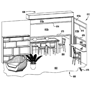
FIG. 50 is a perspective view of an illustrative group of interior rooms with
two roll-up
acoustic barrier systems in accordance with the present invention;
FIG. 51 is a perspective view of an exemplary embodiment of a vertical
assembly of the roll-
up acoustic barrier systems of FIG. 50;
FIG. 52 is partial sectional view of an exemplary top box and the vertical
assembly of FIG.
51;
FIG. 53 is a cross-sectional view of the vertical assembly of FIG. 52;
FIG. 54 is a schematic view of an exemplary tube and flexible barrier material
in relation to
the vertical assembly of FIG. 3;
FIG. 55 is a top view of an exemplary embodiment of an entry guide of the
vertical assembly
of FIG. 51;
FIG. 56 is a bottom perspective view the entry guide of FIG. 55;
FIG. 57 is schematic view of the top box and the vertical assembly of FIG. 52
in a lowered
configuration;
FIG. 58 is schematic view of the top box and the vertical assembly of FIG. 52
in a raised
configuration;
FIG. 59 is an exemplary embodiment of a tube connector insert and zipper in
accordance with
the present invention;
FIG. 60 is a schematic view of an exemplary tube and the tube connector insert
and zipper of
FIG. 59 in an assembled configuration;
FIG. 61 is a schematic view of the tube, tube connector insert, and zipper of
FIG. 60 in an
assembled configuration;
FIG. 62 is a sectional view of an exemplary horizontal track assembly of a
roll-up acoustic
barrier system in accordance with the present invention;
FIG. 63 is a partially exploded view of the horizontal track assembly of FIG.
62;
FIG. 64 is schematic view of an exemplary embodiment of a flexible material
barrier segment
and zipper locking device of FIG. 63 in an unassembled configuration;
FIG. 65 is cross-sectional view of the flexible material barrier segment and
zipper locking
device of FIG. 63 in a rigid receiving channel of an exemplary side track.
FIG. 66 is a partially assembled view of the horizontal track assembly of FIG.
63;
FIG. 67 is a schematic view of the horizontal track assembly of FIG. 63
positioned in an
exemplary side track;
6
CA 02949089 2016-11-14
WO 2015/176047 PCT/US2015/031258
FIG. 68 is a cross-sectional view of exemplary embodiments of a skeleton,
vertical assembly,
and double side track in accordance with the present invention;
FIG. 69 is a cross-sectional view of another configuration of the skeleton,
vertical assembly,
and double side track of FIG. 68;
FIG. 70 is a cross-sectional view of another configuration of the skeleton,
vertical assembly,
and side track of FIG. 68
FIG. 71 is a cross-sectional view of another configuration of the skeleton,
vertical assembly,
and double side track of FIG. 68;
FIG. 72 is cross-sectional view of an exemplary embodiment of a center track
assembly in
accordance with the present invention;
FIG. 73 is cross-sectional view of an exemplary zipper locking device joining
two illustrative
segments of flexible barrier material in accordance with the present
invention;
FIG. 74 is a partially exploded view of the center track assembly of FIG. 72;
FIG. 75 is a perspective view of two center tack components and two segments
of flexible
barrier material in an engaged and unlocked configuration;
FIG. 76 is a cross-sectional view of the center tack components and two
segments of flexible
barrier material of FIG. 75;
FIG. 77 is a perspective view of two center tack components and two segments
of flexible
barrier material in a locked configuration;
FIG. 78 is a cross-sectional view of the center tack components and two
segments of flexible
barrier material of FIG. 77;
FIG. 79 is a perspective view of two center tack components and two segments
of flexible
barrier material in a locked and secured configuration;
FIG. 80 is a cross-sectional view of the center tack components and segments
of flexible
barrier material of FIG. 79;
FIG. 81 is a partial perspective view of the center track assembly of FIG. 72,
the zipper
locking device of FIG. 73, and a side track of FIG. 53;
FIG. 82 is a perspective view of an exemplary embodiment of a locking end cap
in
accordance with the present invention;
FIG. 83 is another perspective view of the locking cap of FIG. 82;
FIG. 84 is a side view of the locking cap of FIG. 82;
FIG. 85 is a rear view of the locking cap of FIG. 82;
FIG. 86 is a front view of the locking cap of FIG. 82;
FIG. 87 is a top view of the locking cap of FIG. 82;
FIG. 88 is a cross-sectional view of exemplary embodiments of a skeleton,
vertical assembly,
and double side track in accordance with the present invention;
7
CA 02949089 2016-11-14
WO 2015/176047 PCT/US2015/031258
FIG. 89 is a cross-sectional view of another exemplary embodiment of a side
track in
accordance with the present invention;
FIG. 90 is a cross-sectional view of another exemplary embodiment of a side
track in
accordance with the present invention;
FIG. 91 is a cross-sectional view of another exemplary embodiment of a side
track in
accordance with the present invention;
FIG. 92 is a cross-sectional view of another exemplary embodiment of a side
track in
accordance with the present invention;
FIG. 93 is a cross-sectional view of another exemplary embodiment of a side
track in
accordance with the present invention;
FIG. 94 is a cross-sectional view of another exemplary embodiment of a side
track in
accordance with the present invention;
FIG. 95 is a cross-sectional view of another exemplary embodiment of a side
track in
accordance with the present invention;
FIG. 96 is a cross-sectional view of another exemplary embodiment of a side
track in
accordance with the present invention;
FIG. 97 is a cross-sectional view of another exemplary embodiment of a side
track in
accordance with the present invention;
FIG. 98 is a cross-sectional view of another exemplary embodiment of a side
track in
accordance with the present invention;
FIG. 99 is a cross-sectional view of another exemplary embodiment of a side
track in
accordance with the present invention;
FIG. 100 is a cross-sectional view of another exemplary embodiment of a side
track in
accordance with the present invention;
FIG. 101 is a cross-sectional view of another exemplary embodiment of a side
track in
accordance with the present invention;
FIG. 102 is a cross-sectional view of another exemplary embodiment of a side
track in
accordance with the present invention;
FIG. 103 is a cross-sectional view of another exemplary embodiment of a side
track in
accordance with the present invention;
FIG. 104 is a cross-sectional view of another exemplary embodiment of a side
track in
accordance with the present invention;
FIG. 105 is a cross-sectional view of another exemplary embodiment of a center
track
assembly in accordance with the present invention;
FIG. 106 is a cross-sectional view of another exemplary embodiment of a center
track
assembly in accordance with the present invention;
8
CA 02949089 2016-11-14
WO 2015/176047 PCT/US2015/031258
FIG. 107 is a cross-sectional view of another exemplary embodiment of a center
track
assembly in accordance with the present invention;
FIG. 108 is a cross-sectional view of another exemplary embodiment of a center
track
assembly in accordance with the present invention;
FIG. 109 is a cross-sectional view of another exemplary embodiment of a center
track
assembly in accordance with the present invention;
FIG. 110 is a cross-sectional view of another exemplary embodiment of a center
track
assembly in accordance with the present invention;
FIG. 111 is a cross-sectional view of another exemplary embodiment of a center
track
assembly in accordance with the present invention;
FIG. 112 is a cross-sectional view of another exemplary embodiment of a center
track
assembly in accordance with the present invention;
FIG. 113 is a plan view of an exemplary embodiment of a roll-up acoustic
barrier 608' in a
commercial office setting;
FIG. 114 is a schematic diagram of acoustic testing equipment in the
commercial office space
of FIG. 113 arrayed for measuring insertion loss across the roll up acoustic
barrier 608';
FIG. 115 is a graph showing measured insertion loss across the roll up
acoustic barrier 608' of
FIG. 114.
DESCRIPTION
FIG. 1 is a perspective view of a patio enclosure 10 formed by three
retractable wall systems
12, 14, 16. The first retractable wall system 12 may be disposed perpendicular
to the house and may
extend from the side of the house to a first corner of the patio. The second
retractable wall system 14
may be disposed perpendicular to the first retractable wall system 12 and may
be parallel to the
sliding door of the house. The third retractable wall system 16 may be next to
the second retractable
wall system 14. The first retractable wall system 12 may be disposed in an
opening under the roof
structure of the house. The first retractable wall system 12 may include a
head rail 18, a left side track
20, right side track 22, and a horizontal track 24 disposed between the left
side track 20 and the right
side track 22. In a preferred embodiment, the left side track 20, the right
side track 22 and the
horizontal track 24 have the same cross-sectional profile.
In FIG. 1, the first retractable wall system 12 is in a raised configuration.
In the raised
configuration the horizontal track 24 abuts the head rail 18. Referring to
FIG. 3, the head rail 18 may
contain a roll of flexible barrier material 26a, as well as a mechanism (not
shown) 28 for raising and
lowering the flexible barrier membrane 26. As shown in FIG. 2, the mechanism
28 may include an
electrical motor 42, which may be controlled by a wireless remote or switch.
Alternatively, the
mechanism may include a hand crank or a chain drive with a looped strap for
manually raising and
lowering the flexible barrier membrane.
9
CA 02949089 2016-11-14
WO 2015/176047 PCT/US2015/031258
Referring to FIG. 1, the left side track 20 of the first retractable wall
system 12 may be
secured to the building. By contrast, the right side track 22 of the first
retractable wall system 12 may
be connected to the left side track 32 of the second retractable wall system
14 at a 90 degree angle to
form a corner assembly. The second retractable wall system 12 is shown in a
partially lowered
configuration. A flexible barrier material 34 may be disposed between the left
side track 32, right side
track 36 and horizontal track 38 of the second retractable wall system 14. The
flexible barrier material
34 may extend from inside each of these three tracks 32, 36, 38 to create a
wall.
As shown in FIG. 3, the flexible barrier material 26 may be disposed on a tube
40 in the head
rail. The flexible barrier material 26 may be rolled onto the tube 40 and
unwound from the tube as the
horizontal track 24 is lowered. Referring to FIG. 1, the third retractable
wall system 16 may be
disposed parallel to the second retractable wall system 14. The right side
track of the second
retractable wall system 14 and the left side track of the third retractable
wall system 16 may be
secured together or connected to a secondary structural member (e.g., a post
or stud). The third
retractable wall system 16 is shown in the lowered configuration.
FIG. 2 shows an exploded view of the first retractable wall system 12. The
retractable wall
system 12 may include a left side track 20, a right side track 22, and a
horizontal track (or weight bar)
24 extending between the left side track and the right side track.
Additionally, the retractable wall
system 12 may include a left side end-cap 46 which is secured into the left
side track 20 and a left side
feeder-clip 48 that is positioned in the left side end-cap 46. Similarly, the
retractable wall system 12
includes a right side end-cap which may be secured into the right side track
22, as well as a right side
feeder-clip 52 that may be disposed in the right side end-cap 50. When the
left side end-cap 46 is fully
seated in the left side track 20 the left side feeder-clip 48 interlocks with
features of the left side track
20 cross sectional profile to further secure the left end-cap to the left side
track. Similarly, when the
right side end-cap 50 is fully seated in the right side track 22, the right
side feeder-clip 52 interlocks
with features of the right side track 22 cross-sectional profile to further
secure the right end-cap to the
right side track. Each end-cap 46, 50 further may include a cylindrical stub
54 in the end-cap wall.
The cylindrical stub 54 may receive the tube assembly and serve as axis of
rotation for the tube 40.
The roller tube assembly may include an idler 56, a tube 40 having a central
axis, and a
mechanism 28 for rotating the tube 40 about the central axis of the tube. In a
preferred embodiment,
the mechanism 28 may include a motor 42 that is partially installed with the
tube 40. The motor 42
may include a built in radio control receiver that provides a user the
capability to operate the motor
with a remote control. For example, the motor may be a Somfy RTS motor.
In FIG. 2, the mechanism 28 for rotating the tube includes a motor 42 with a
remote control.
The motor, which may be slidably received within the tube 40, may include a
drive 58 and a crown
60. The drive 58 and crown 60 may be external features of the motor which
interlock with an interior
surface 62 of the tube so as to provide a mechanism for transferring
rotational movement from the
motor or the tube. The motor 42 further may include a drive wheel 64 at one
end. The drive wheel 64
CA 02949089 2016-11-14
WO 2015/176047 PCT/US2015/031258
may be configured and dimensioned to be fixedly received within a motor
bracket 66. The motor
bracket 66 may be secured to one end-cap 50. The tube assembly 28 further may
include a sheet of
flexible material 26. The sheet of flexible material 26 may include a zipper
border 68 on at least three
sides. The sheet of flexible material 26 may be cut to be received in a pair
of traveling guide pieces
70, 72 that are adapted to be received in the horizontal track 24.
FIG. 3 shows a cross-section of the retractable wall system 12 taken
perpendicular to the
central axis 74 of the tube 40. The tube 40 may be mounted on the cylindrical
stub 54 of the left end-
cap 46. The tube 40 may be secured to the idler 54 with a fastener. Inside the
tube 40 are interior wall
segments 78, which form a mating structure for the motor drive and crown. The
interior wall
segments 78 may be arranged to provide structural rigidity to the tube. In
particular, the interior wall
segments may span the internal space of the tube 40 so as to provide a three
dimensional truss or
space frame. Additionally, the tube may include a fabric pocket receiving
channel 80 and a fabric
zipper receiving channel 82, which may be used to connect the flexible barrier
material 26 to the tube
40. Wrapped around the tube 40 is a sheet of flexible barrier material 26a,
which may include a heat
bonded zipper edge 68 on the left side and the bottom side of the sheet.
The end-cap 46 may be situated within the left side track 20. The left side of
the flexible
barrier material sheet 26 may be fed through the left side feeder-clip 48 into
a rigid receiving channel
84a in the left side track 20. The bottom side of the flexible barrier
material 26 sheet may be received
within the horizontal track 24. The cross-sectional profile of the left side
track 20 and horizontal track
24 may be the same. Accordingly, the flexible barrier material 26 may be
secured to the horizontal
track 24 through a rigid receiving channel 86 in the horizontal track 24. A
slot 88 may connect the
rigid receiving channel 86 to an internal anchoring cavity 90 that is
configured and dimensioned to
receive the bonded zipper edge 68 of the sheet. The rigid receiving channel 86
may be disposed
between a pair of arcuate walls 92. The internal anchoring cavity 90 may be
disposed adjacent to the
rigid receiving channel 86.
The horizontal track 24 further may include a primary accessory receiving
channel 94, a
secondary accessory receiving channel 96, and a tertiary accessory receiving
channel 98. Weights, for
example, steel bars 100 may be placed with the primary accessory receiving
channel 94 or the
secondary accessory receiving channel 96 of the horizontal track 24 to
facilitate lowering of the
flexible material barrier 26. In another example, sound dampening material may
be inserted in these
spaces to increase the sound insulating properties of the retractable wall
system. An elastomeric end
cap, flexible seal, or brush may be inserted in the tertiary accessory
receiving channel 98 to provide an
improved connection with the ground surface for purposes such as, without
limitation, increasing wall
stability, slip resistance, draft prevention, or sound dampening.
FIG. 4 shows a cross section of a preferred embodiment of the tube 40.
Generally, the tube 40
may be a thin-wall hollow member. The outer surface 102 of the tube may be
substantially circular,
and the interior space of the tube may include a series of interior wall
segments (or structural
11
CA 02949089 2016-11-14
WO 2015/176047 PCT/US2015/031258
members) 78, which may reinforce the tube against bending moments that may be
generated from the
weight of flexible barrier material on the tube when the tube is positioned
between the end caps. Each
structural member 78 may form a cord within the tube 40. Each structural
member 78 may connect to
an adjacent structural member 78 to form an external node 104, which is
located about the
circumference of the tube. Additionally, each structural member 78 may
intersect two other structural
members 78 to form a pair of internal nodes 106. The intersection of a pair of
structural members 78
at an external node 104 forms a right angle. The intersection of a pair of
structural members 78 at an
internal node forms an obtuse angle of approximately 135 degrees. The space
between an internal
node 106 and outer wall 108 of the tube may be used to house the pocket
receiving channel 80 and the
zipper receiving channel 82. Additionally, a fastener alignment groove 110 may
be disposed above
one or more internal nodes on the outer surface 102 of the tube. The interior
surface 62 of the tube
may form an eight sided shape for receiving a motor (with a mating drive and
crown) or an octagonal
tube for non-motorized applications (e.g., 40 mm, 60 mm, or 80 mm tubes).
FIG. 5 shows the cross-section of another embodiment of the tube 40'. In this
embodiment,
the outer surface 112 of the tube 40' is substantially circular and the
interior space includes a series of
structural members 114 that reinforce the tube 40' from bending moments as in
the previous
embodiment. In contrast to the tube of FIG. 4, however, each structural member
114 connects to the
outer wall 116 of the tube at one location (or external node) 118.
Additionally, the opposite end of
each structural member 114 may connect to an adjacent structural member 114 to
form an internal
node 120. The interior surface 122 of the tube 40' may form an eight sided
shape for receiving a
motor (with a mating drive and crown) or an octagonal tube for non-motorized
applications (e.g., 40
mm, 60 mm, or 80 mm tubes). In this embodiment, the tube 40' also may include
a pocket receiving
channel 124, a zipper receiving channel 126, and two fastener alignment
grooves 128.
Referring to FIGS. 4 and 5, the tube 40, 40' may have an outer diameter of
approximately 1.0
inches to approximately 6.0 inches, but other dimensions may be used where
appropriate for the
application. In an exemplary embodiment, the tube 40, 40' may have an outer
diameter of
approximately 3.5 inches and an interior surface 62, 122 which is configured
and dimensioned to
receive a 60 mm octagonal tube. Additionally, the tubes 40, 40' may range from
approximately one
foot long to approximately 30 feet in length. The tube 40, 40' may be formed
from aluminum or an
aluminum alloy (e.g., 6061 aluminum alloy (International Alloy Designation
System)), however,
other suitable metals, alloys or materials may be used to form the tube
provided the material has
sufficient strength. For example, the tube 40, 40' may be formed from a carbon
graphite reinforced
polymer material. Preferably, the tube 40, 40' may be formed by materials
having a high strength to
weight ratio and the ability to be manufactured using extrusion technologies.
Referring to FIG. 4, the flexible barrier material 26 may be secured to the
tube 40 by a pocket
of flexible barrier material 130 and rod 132 inserted within the pocket
receiving channel 80. In
another alternative, the flexible barrier material 26 may be attached to a
zipper 68 that is inserted into
12
CA 02949089 2016-11-14
WO 2015/176047 PCT/US2015/031258
the zipper receiving channel 82. Generally, the flexible barrier material 26
may range from
approximately 1/32 of an inch in thickness to approximately 1/2 inch in
thickness. The flexible barrier
material 26 may be formed, without limitation, from natural fibers, leather,
PVC, polyester, or acrylic
materials. Preferably, the flexible barrier material 26 may range from
approximately 7 ounces to 60
ounces in weight. In one example, the flexible barrier material 26 may be
constructed from a 20 ounce
vinyl fabric. In another example, the flexible barrier material 26 may be
constructed from a vinyl
fabric that is capable of receiving a print design. In another example, the
flexible barrier material 26
may be constructed from a screen, a transparent material or a natural fabric.
The flexible barrier material 26 may be a single layer of material or a
multilayer material
formed from two or more layers of material. For example, the flexible barrier
material 26 may be
formed from three layers: a middle layer having enhanced sound dampening
properties (e.g., mass
loaded vinyl, Acoustiblokg) and two outer fabric layers (e.g., cotton,
polyester, rayon, vinyl, wall
paper, or wall covering material) to create an acoustic barrier. In another
example, the flexible barrier
material 26 may be formed from clear plastic sound blocking material.
Preferably, a flexible barrier
material with enhanced sound dampening properties may have a STC (Sound
Transmission Class)
rating of 26 or greater.
FIG. 6 shows an exploded view of the idler 56 and the tube 40 of FIG. 4. One
end 134 of the
idler 56 may be inserted into the tube 40. The opposite end 136 of the idler
56 may be mounted on the
end-cap cylindrical stub 54 (not shown) to form an axis of rotation. The tube
40 may include one or
more fastener alignment grooves 110. As shown in FIG. 7, a drill (or fastener)
138 may be placed in a
fastener alignment groove 110 to create a fastener alignment path 140 for
securing the idler 56 to the
tube 40. The fastener alignment groove 110 may be located above an internal
node 106 of the tube.
Placement of a fastener alignment groove 110 above an internal node 106
provides a mechanism for
promoting a repeatable, quick, and straightforward method of securing the
idler 56 and the tube 40
with a fastener 138. More particularly, the fastener path 140 connects the
fastener alignment groove
110 and the internal node 106 of the tube. A fastener that is aligned in this
manner may be expected to
penetrate the tube 40 beneath the fastener alignment groove 110 and be guided
by adjacent internal
structural members 78 to a position above the internal node 106. This fastener
path may provide a
secure connection because the fastener may be driven perpendicular to the
outer surface of the tube
wall and through the internal node 106 before advancing into and securing the
idler 56.
FIG. 8 shows the left side of the flexible barrier member 26 disposed in the
left side feeder-
clip 48 and left side track 20 of the retractable wall system 12. Also, the
bottom of the flexible
membrane barrier 26 is shown locked into the horizontal track 24. As shown in
FIG. 8A, the left side
of the flexible material barrier is fully seated within the traveling guide
pin 72. The full length square
cut double pin construction 142 provides rigid reinforcement of the flexible
barrier material 26 at a
leading edge 144 of the sheet. As the leading edge of the sheet 144 may be
subject to compressive and
sheering forces as the barrier is lowered, the traveling guide pin 72 may
prevent the flexible barrier
13
CA 02949089 2016-11-14
WO 2015/176047 PCT/US2015/031258
material 26 from wearing, tearing, bunching or binding in the vertical track
20 when the horizontal
track 24 is lowered or raised.
Moreover, as shown in FIG. 9, the traveling guide pin 72 may be configured and
dimensioned
to be slidably received within the rigid receiving channel 84 of the vertical
track 20. As the fasteners,
which secure the flexible membrane barrier 26 to the traveling guide pin 72
are located with the rigid
receiving channel 84, they may be recessed or flush with the exterior surfaces
of the traveling guide
pin 72. The zipper portion 68 of the flexible membrane barrier 26, when
disposed in the internal
anchoring cavity 90, pulls the traveling guide pin 72 into the rigid receiving
channel 84 of the vertical
track 20. In this manner, the horizontal track 24 and the sides of the
flexible membrane barrier 26 may
be securely positioned within the left side track 20 and the right side track
22.
The reinforcement of the flexible barrier material 26 and tension across the
vertical tracks 20,
22 may increase the structural integrity of retractable wall system 12,
provide for more reliable
operation of the system, and reduce mechanical fatigue of the zipper-material
interface. Also, the
generally uniform tension across the flexible membrane barrier 26 may increase
the aesthetic appeal
of the retractable wall system 12 by enhancing a uniform appearance of the
flexible barrier material
across the structure. Moreover, in outdoor applications, this construction may
prevent drafts. In sound
barrier applications, this construction may promote the deployment of a
continuous sound dampening
barrier and prevent fugitive sound emissions from passing individual barrier
elements to reduce the
effective sound dampening properties of the retractable wall system. Sound
dampening material may
be placed in the primary accessory receiving channel 232, the secondary
receiving channel 234, and
the arcuate receiving channels 236 as well.
The vertical track 20 of the retractable wall system may be secured to a
structural member
such as a stud or post. A pilot hole may be drilled and then a larger access
hole placed in the track 20
to allow a fastener 150 to be advanced though the opposite side the track and
into external structural
framing 148 to securely attach the vertical track 20 to structural framing of
an adjacent wall or post.
Referring to FIGS. 10 and 15, the horizontal track 24, the left side track 20,
and the right side
track 22 may share a single cross-sectional profile 152. In FIG. 10, the track
profile 152 is shown in
use as a horizontal track 24. In this configuration, the primary accessory
receiving channel 94 may
accommodate a weight bar 100, which may be a 1/2 inch by 3/4 inch steel bar.
The weight bar 100
may be positioned within the primary accessory receiving channel 94 by the end-
cap stem blocking
member 154, the upper rail guide 156, and the lower rail guide 158.
In FIG. 11, the cross-sectional profile of the track 152' is substantially the
same as in FIG. 10,
but a front portion 160 of the track 24' is removable and forms a cover. The
removable portion 160
may be secured to the track 24' with snap fittings 162. This feature allows
weight bars 100 to be
installed in the horizontal track 24' after the retractable wall structure 12
has been erected. This may
improve constructability of the system and enhance the safety of workers
because handling the
14
CA 02949089 2016-11-14
WO 2015/176047 PCT/US2015/031258
horizontal track with preloaded weight bars 100 is significantly heavier than
handling an empty
horizontal track.
FIGS. 10 and 11 show an elastomeric cap 164 disposed in the tertiary accessory
channel 96.
Arcuate, upper receiving channels 166, as well as the primary and secondary
accessory receiving
channels 94, 96 may receive sound damping materials to enhance the sound
dampening effect of the
retractable wall system.
FIG. 12 shows the left feeder-clip 48 and its tapered guide hole 168. The
tapered guide hole
168 receives the zippered edge 68 of the flexible barrier material 26 as it
spools off the tube (not
shown). Similarly, FIG. 12 and FIG. 13 show the right feeder-clip 52 and its
tapered guide hole 170,
which receives the zippered edge 68 of the other side of the flexible barrier
material 26. The right
feeder clip 52 may further include a circular passage 172 for receiving a
power cord 174 from the
motor 42.
Referring to FIG. 14, the right end-cap 50 may include a stem 176 having a
rectangular
channel 178. The right side feeder-clip (or entry guide) 52 may include a
beveled top surface 180, a
central base portion 182, and four plugs 184, 186, 187, 188. One end of the
feeder-clip 52 may
include an elongated and corrugated plug 184. Next to the elongated and
corrugated plug 184 and
disposed in the middle of the feeder-clip 52 may be a second plug 186. The
second plug 186 may be
wider and shorter than the elongated corrugated plug 182. Also, a pair of
contra-lateral plugs 188, 190
may be disposed on the other side of the second plug 186.
The right feeder-clip 52 may include a circular passage 172 that extends from
the beveled top
surface 180 through the second plug 186. The passage 172 may be configured and
dimensioned to
receive an electrical cable for the motor. Additionally, the beveled top
surface 180 may include a first
tapered rectangular passage 170 which extends through the feeder-clip 52. A
second rectangular
passage 192 may extend from the beveled top surface 180 through the feeder-
clip 52 between the
contra-lateral plugs 188, 190. The first rectangular passage 170 and the
second rectangular passage
192 may be separated by a thin wall 194. The thin wall 194 may include a
tapered slit 176 which
extends from the top of the thin wall to the bottom of the thin wall.
As shown in FIG. 15 the right feeder-clip 52 may be inserted into the
rectangular channel 178
of the end-cap 50. The stem 176 of the end-cap may be seated within the
primary accessory channel
198 and may be positioned in the primary accessory channel 198 by the upper
guide rail 200, the
lower guide rail 202, and the end-cap stem blocking member 204. The second
plug 186 of the feeder-
clip 52 may be received in the secondary accessory receiving channel 206. The
secondary accessory
receiving channel 206 may be used to accommodate an electrical cable 174 that
extends from the
motor 42 to an electrical outlet outside the track. The pair of contra-lateral
plugs 188, 190 may be
disposed in the opposing arcuate cavities 208 at the front of the track. The
traveling guide member 72
may be disposed in the rectangular receiving channel 210 of the track and the
zippered end 68 of the
flexible membrane barrier 26 may be disposed in the internal anchoring cavity
212. The material
CA 02949089 2016-11-14
WO 2015/176047 PCT/US2015/031258
connecting the zipper 68 and the flexible membrane barrier 26 may be disposed
in the slot 214
between the rectangular receiving channel 210 and the internal anchoring
cavity 212.
FIG. 16 shows an exemplary corner assembly 216 formed from a first end-cap and
track 218
and a second end-cap and track 220. The first end-cap and track 218 and the
second end-cap and track
220 may be disposed at an approximately 90 degree angle. The corner assembly
216 may be used to
construct adjacent retractable wall systems, as shown in FIG. 1.
FIG. 17 shows an exemplary alignment of two tracks 22, 20 which may be used to
construct a
corner assembly 216. In the track alignment, the alignment groove 222 in the
primary accessory
receiving channel 198 may be disposed opposite the tertiary accessory groove
226 of the adjacent
track. FIG. 17a shows how the two tracks 20, 32 may be securely fastened to
each other. In a
preferred method, a guide hole may be drilled between the upper and lower
guide rails 200, 202 in the
primary accessory receiving channel 198. The guide hole may be enlarged to an
entry hole in order to
provide access to the interior of the primary accessory receiving channel. A
fastener 228 may be
positioned in the alignment groove 222 (FIG. 17) and advanced into the
tertiary accessory groove 226
(FIG. 17) of the adjacent track. The enlarged hole may be covered with a
plastic cap 230.
Referring to FIG. 18, four corner assemblies 216 may be used to construct a
free standing
structure. The free standing structure may be formed from four (or more)
retractable wall systems
240a, 240b, 240c, 240d, 240e. Two retractable wall systems 240c, 240d may be
joined together to
form one side of the structure. One of the retractable wall systems 240c may
be used as a door for the
structure.
Referring to FIG. 19, a short ledge 242 may extend from the lower portion of
the head rail
into the enclosed space. The short ledges 242 of opposing retractable wall
systems 240b, 240e may be
used to support beams 244, which may form a cover for the structure 238. The
beams may be used to
form a continuous cover or a lattice cover. For example, wood boards (e.g.,
1"x2" or 2"x4" boards)
may be supported by the head rail ledges to form a lattice cover, which may
allow the structure to be
used as a temporary booth (or Sukkah) that is constructed for use during the
Jewish festival of Sukkot.
Referring to FIG. 20, the retractable wall system may be adapted for use as an
awning 246. A
webbing material may 248 be molded to the flexible membrane barrier 250 that
forms the awning
cover in order to make the canopy stronger while maintaining light weight. The
awning 246 may
include a side pennant 252. As shown, in FIG. 21, the side track of the
retractable wall system may be
modified such that the side frame 254 incorporates a reinforced flexible
membrane barrier connection
256 to provide a taunt but retractable ceiling canopy. The side frame 254 may
include a roller track
258 for a wheel 260 which is connected to the front crossbar 262. Also, the
side frame 254 may
include a gutter 264 for collecting and transporting rain water 266. An
exterior groove 268 on the side
frame may be used to house a sealant for sealing the frame to a structure or
an abutting awning frame.
As depicted in FIG. 21, FIG. 22 and FIG. 23, a reinforced flexible membrane
barrier
connection 256 may be used to deploy a side pennant 252 with the ceiling
canopy. Referring to FIG.
16
CA 02949089 2016-11-14
WO 2015/176047 PCT/US2015/031258
23, the front cross bar 262 may support a bracket 270 that holds a loop of
canopy material 272 to form
a pocket to collect and direct rain water 266 to the gutter 264. The front
partition 274 of the awning
structure 246 may include a channel 276 for receiving water from the gutter.
In another embodiment,
the gutter and wheel track may include the same structure. The front partition
274 further may include
a solenoid 278 that may be used to lock the awning in the deployed
configuration. Additionally, a
brake (not shown) may be available on the motor end and the non-motor end of
the awning spool. The
retractable wall system may be constructed from materials selected to better
withstand changes in
temperature, corrosion, or degradation from ultraviolet light.
Referring to FIG. 24, the cross-sectional profile of the track 300 is
generally the same as in
FIG. 10, but a first portion 302 of the track 300 may be removable, and may
form a cover. The
removable portion (e.g., Part 1) 302 may be secured to a receiving (or base)
portion 304 (e.g., Part 2)
with one or more snap fitting(s) 306. In an exemplary embodiment, the snap
fitting 306 may be a
mechanical joint system where part-to-part attachment is accomplished with
locating and locking
features that are homogenous with one or the other of the components being
joined. Joining may
require the (flexible) locking features to move aside for engagement with the
mating part, followed by
return of the locking feature toward its original position to accomplish the
interference required to
latch the components together. Locator features may be inflexible, providing
strength and stability in
the attachment. Each snap fitting (or snap fit locking pair) 306 may be formed
from a hook 308 and an
undercut 310. In FIGS. 24 and 25, the undercut 310 may be a cantilevered lug;
and the hook 308 may
be a lip or projection that snaps into the undercut. Assembly of the snap
fitting 306 may require
temporary deformation of one or both pieces, but the parts may return to an
unstressed state in the
final assembled position. Additionally, the retaining force of a cantilevered
lug may be a function of
the bending stiffness of the cantilevered lug. Thus, the lugs may be loaded
partially to achieve a tight
assembly. Although the retention of each snap fit locking pair 306 may be
releasable, the retention
may be peimanent in certain applications.
As shown in FIG. 24 and FIG. 25, a retention wall 312 and a guide wall 314 may
be
configured and dimensioned to retain an accessory in the primary receiving
channel 316. For
example, the retention wall 312 and guide wall 314 may foim parallel sides of
a channel 318 that may
hold the accessory, for example, an entry guide piece 320 within the primary
receiving channel 318 of
the track when the cover 302 is removed from the receiving portion 304. In
FIG. 24, the track is
shown in an assembled (or locked) configuration 322. During installation the
recessed, square profile
324 of the upper contour of the track 326 may allow the track to integrate
smoothly with drywall and
other construction materials without the appearance of cracks or spaces
between the finished drywall
and track.
Referring to FIG. 25, the track 300 may have a released configuration 328 in
which the cover
302 is separated from the other part (Part 2) 304. Thus, the cover 302 may be
attached to receiving
portion 304, after the receiving portion 304 has been connected to other
structural members of the
17
CA 02949089 2016-11-14
WO 2015/176047 PCT/US2015/031258
retractable wall system. For example, the entry guide 320 may include a high
side fitting 330, a low
side fitting 332, a block 334, and a stem 336, which arc configured to attach
to the receiving portion
304 only. Likewise, the cover 302 may be removed from the receiving portion
304 after the
retractable wall system has been installed. This severability feature allows
weight bars to be installed
in the primary receiving channel 316 of a horizontal track of a previously
erected retractable wall
system. It also allows for cabling (e.g., structural, control, or electric
cable) to be run through the
secondary receiving channel 338 after the retractable wall structure (or
awning) has been assembled.
Moreover, sound proofing material may be placed inside the track after the
retractable wall structure
(or awning) has been assembled. The severability feature may improve the
constructability of the
system, as well as enhance worker safety because handling a track with
preloaded weight bars is
significantly heavier than handling an empty horizontal track.
Referring to FIG. 2, in one embodiment of the retractable wall system 12 one
end of the tube
(40, 40') receives a motor assembly 28. A portion of the motor assembly may be
secured to the
bracket 90. The other end of the tube may receive an idler 56. The idler may
include a ring of ball
bearings that may be disposed on the end cap pin 54. In another embodiment,
the idler may be spring
loaded. In yet another embodiment the idler may be replaced with a "Chinese
spring," which stores
energy as the retractable wall is lowered and releases stored energy as the
retractable wall is raised.
The energy released by these devices may assist in retracting the wall. An
energy storage device (e.g.,
a spring loaded idler or "Chinese spring") may be used in combination with a
manual gearbox on the
one end of the tube, in place of the electric motor assembly. Alternatively,
an energy storage device
may be used in combination with a chain drive mechanism on one end of the
tube, instead of the
electric motor assembly.
Referring to FIG. 26 and FIG. 27, an adaptor flange 340 may be used to connect
a retractable
wall system (FIG. 2) tube 40 to the end caps 46, 50. The adaptor flange 340
may have a flange 342
disposed between two working end portions 344. For example, one working end
portion 346 of the
adaptor flange may be configured and dimensioned to mate with the tube. By
contrast, the other end
348 of the adaptor flange may be configured and dimensioned to mate with a
customized insert 350
(FIG. 31 and FIG. 32) which in turn may be adapted to connect to a gear box,
drive chain, or mounted
on an end cap pin or like bracket.
Referring to FIG. 28, the tube mating portion 346 may include one or more
faces 352 that
interlock with the internal features of the tube. For example, the one or more
faces 352 of the tube
mating portion 346 may be configured and dimensioned to form a press fit plug
with the tube. For
instance, interior wall segments or structural members 78 (FIG. 9) of the tube
may receive and retain
the press fit plug. The press fit plug may include four drive faces 354 and
four rail faces 356. In one
embodiment, a rail face 356 may include a base 358 and at a fin 360. Although
the embodiment of the
tube mating portion shown in FIG. 28 has an axis of symmetry, any
configuration of plug features and
fasteners may be used to connect with the tube end, provided the tube mating
portion 346 is securely
18
CA 02949089 2016-11-14
WO 2015/176047 PCT/US2015/031258
connected to the tube, rotation of the flange 342 turns the tube about an
axis, and the structure can
readily withstand the torque necessary to rotate the tube.
Referring to FIG. 29, the insert mating portion 348 may include a tube member
358 that is
configured and dimensioned to mate, for example, with an idler, a spring
loaded idler, an electric
motor assembly, or a "Chinese spring." Additionally, the hollow, tube member
358 may be
configured and dimensioned to mate with the reversible insert of FIG. 31. In
the embodiment shown
in FIG. 29, the hollow, tube member 358 is circular cylindrical, however, a
cylinder of any shape may
be used provided that the tube member is adapted to cooperate with a drive
mechanism (or hinge
joint) that may be connected to (or cooperate with) an end cap. The outer
surface of the hollow tube
member 358 further may include structural elements 360 that reinforce the
flange-tube member
interface against sheering forces. The structural members 360 may include a
plurality of reinforcing
members. One (or more) of the reinforcing members 360 may form a buttress
between the tube
member 358 and the flange 342.
The adaptor flange 340 may have a leading end 362, a trailing end 364, and an
internal side
wall 366 extending from the leading end to the trailing end. The internal side
wall may define a
passage through the adaptor flange 340. The internal side wall 366 may include
one or more grooves.
A groove 368 may extend from the leading end 362 to an interior location on
the internal side wall
366. Another groove(s) 370 may have a square cut. Yet another groove 372 may
be spaced from the
leading end groove 368 and the square cut groove(s) 370 on the side wall. The
square cut groove(s)
370 may be configured and dimensioned to receive a raised key on the crown of
an electrical motor
assembly or similar accessory. For instance, the one or another square cut
groove(s) 370 may be
configured to receive one or more raised keys on the head of a Chinese spring.
Additionally, the
leading end groove(s) 368, 372 may be configured and dimensioned to receive a
radial projection on
the reversible insert 350 (FIG. 31 and FIG. 32). A slot or opening on the
groove 374 may extend
through the side wall to provide a fastener attachment site for securing a
fastener to the adaptor flange
340 and the flange accessory (e.g., crown of electrical motor, Chinese spring,
and reversible insert
350).
FIG. 30 and FIG. 30b show another embodiment of an adaptor flange 376 of the
present
invention. The adaptor flange 376 may be configured and dimensioned to mate
with a conventional
awning tube or a galvanized steel roller tube. In this embodiment, the tube
mating portion 378 may
include three different connectors for securing the tube mating portion 378
within a conventional tube.
For instance, the connectors may include a plurality of blocks 380, primary
rails 382 and secondary
rails 384, as well as a wing that forms a buttress between the flange 342 and
the primary rails 380.
The distribution of the connectors may be uniform or may form a pattern around
the exterior side wall
of the tube mating portion 378. For example, pairs of like connectors may be
disposed about the
circumference of the tube mating portion at a radial interval of approximately
180 degrees. In one
configuration, one primary rail 380 may be disposed next to each lateral edge
of the respective flange
19
CA 02949089 2016-11-14
WO 2015/176047 PCT/US2015/031258
cutouts 388. The primary rails 380 may define a passage 390 behind the flange
cutout 380 that allows
a loop of awning material to be slipped into a tube pocket (see FIG. 33). The
primary rails 380 may be
reinforced with a wing structure 386 that buttresses the primary rail with
respect to the flange. A pair
of blocks 380 may be disposed on either side of the primary rails 384 to
provide additional structural
support for the inner wall of the tube. A pair of secondary rails 384 may be
disposed between two
pairs of blocks 380. Each rail may include a fin 392 that projects beyond an
imaginary circumference
defined by the end surface of the rail base and blocks so as to provide for a
tighter, more secure press
fit to the tube.
FIG. 31 shows an exemplary embodiment of an insert 350. The insert 350 may
include a body
394 foimed from a cylindrical member. The cylindrical member may have a
central axis 396 as well
as a proximal end 398 and a distal end 340. The cylindrical member may be
circular cylindrical. The
cylindrical member may be tapered such that the diameter at one end of the
member is larger than at
the opposite end. The insert 350 may include a nose 402 adjacent to the
proximal end 398. The nose
402 may include a bearing receiving port 404. The bearing receiving port 404
may include an annular
wall 406 that defines a circular cylindrical port which may be configured and
dimensioned to receive
a ring of ball bearings. One or more reinforcing members 408 may connect the
circumference of the
annular wall 406 to the body 394 in order to buttress the nose 402 against
sheering forces. The distal
end 400 of the body 394 may include internal structures 410 that are adapted
to receive the driver of a
gearbox or a pulley chain drive. The insert may further include one or more
radial projections 412 on
the body. Each radial projection 412 may be configured and dimensioned to mate
with a respective
groove 368, 372 on the internal side wall 366 of either adaptor flange
described above. Additionally,
the one or more radial projections 412 may be located on the body 394 such
that: (1) the nose 402
protrudes from the adaptor flange when the distal end 400 is inserted into the
adaptor flange; and (2)
the gearbox or drive chain receiving end 398 are flush with the distal end 400
of the insert when the
nose 402 is inserted in to the adaptor flange. (e.g., FIG. 34). This spacing
differential provides the
necessary space for the gearbox or drive chain assembly in the end cap when
the distal end of the
insert is disposed within the flange. Similarly, the spacing differential
provides the necessary space
for the bearing ring cage to mount on the end cap stub 54 (or similar
structure).
FIG. 32 shows the distal end 400 of the insert of FIG. 31. The distal end 400
of the inset 394
may include a plurality of structural reinforcing members 410 inside the
insert. The orientation of the
structural reinforcing members 410 may be designed to make the insert 394 more
resistant to bending
moments and sheering forces. The internal structural reinforcing members may
provide added rigidity
to the insert 394 so as to prevent bending and cracking of the insert under
the static and dynamic loads
attendant to mounting and operating the tube-flange-insert assembly.
Additionally, the structural
reinforcing members 410 may define a driver receptacle 414 for receiving the
driver of a manually
operated gear box or the driver of a pull chain mechanism.
CA 02949089 2016-11-14
WO 2015/176047 PCT/US2015/031258
As shown in FIG. 33, the tube mating portion 352 of the adaptor flange 340 may
be inserted
into the tube 40 until the flange 342 contacts the end 418 of the tube. The
adaptor flange may be
oriented such that the flange cutouts 416 are generally aligned with the
pocket receptacles 124, 126.
Depending on the application, an insert 350, motor 42, idler or "Chinese
spring" may be placed into
the insert receiving end (or insert mating end) 348 and interlocked with the
appropriate grooves 368,
372 on the internal sidewall 366.
FIG. 34 and FIG. 34b show a rear and front perspective view, respectively, of
two adaptor
flange embodiments 340, 376 with the insert 350 of FIGS. 31-32.
Referring to FIG. 34, one adaptor flange 340 and insert 350 assembly
configuration 542
depicts the insert 350 after being placed within the adaptor flange 340 from
the insert mating portion
348 with the proximal end 398 of the insert 350 facing inward. In this
configuration 542, the bearing
receiving port 404 is not available for use at the working end 344 of the
insert mating portion 348 of
the adaptor flange 340. Instead, the distal end 400 of the insert 350 is
available for use at the working
end 344 of the insert mating portion 348 of the adaptor flange 340. As shown
in FIG. 348, this
configuration of the adaptor flange 340 and insert 350 assembly 542 provides
working access to the
driver receptacle 414 on the distal end of the insert 400. The radial
projection(s) 412 of the insert 350
are disposed and interlocked within the leading end groove(s) 368 of the
adaptor flange 340. The
distal end 400 of the insert 350 may be flush with the working end portion 344
of the adaptor flange
340. In this configuration, the driver of a manual gearbox may be inserted
into the driver receptacle
414 to rotate the adaptor flange 340 and insert 340 assembly 542. Referring to
FIG. 46, internal
structures 410 of the insert 350 strengthen (or reinforce) the assembly 542
from sheering forces and
bending moments associated with a tube connected to the tube mating portion
346 of the adaptor
flange 340. In another operable configuration of the adaptor flange 340 in
which the insert 350 is not
used, one or more square cut grooves 370 may be used to interlock with an
electric motor or spring
assembly. Referring to FIG. 47, a rail face(s) 354 and a drive face(s) 356 of
the adaptor flange 340
may bear on an interior surface(s) 62 of the tube so as to provide a mechanism
for transferring
rotational movement from the driver of a manual gearbox or other device.
Referring to FIG. 34, another adaptor flange 340 and insert 350 assembly
configuration 544,
depicts the insert 350 after being placed within the adaptor flange 340 from
the insert mating portion
348 with the distal end 400 of the insert 350 facing inward. In this
configuration 544, the bearing
receiving port 404 is available for use at the working end 344 of the insert
mating portion 348 of the
adaptor flange 340. The proximal end of the insert 398 may project from the
working end 344 of the
insert mating portion 348. The proximal end of the insert 398 may project from
the working end 344
of the insert mating portion 348 such that a ring bearing placed in the
bearing receiving port 404 may
be received onto a cylindrical stub 54 of an end-cap wall. As shown in FIG.
34B, this configuration of
the adaptor flange 340 and insert 350 assembly 544 provides working access to
the bearing receiving
port 404 on the proximal end of the insert 398. The radial projection(s) 412
of the insert 350 are
21
CA 02949089 2016-11-14
WO 2015/176047 PCT/US2015/031258
disposed and interlocked within the leading end groove(s) 368 of the adaptor
flange 340. In this
configuration 544, a bearing ring cage may be placed in the bearing receiving
port 404, which may be
disposed onto a cylindrical stub 54 of an end-cap wall.
Referring to FIG. 34, another adaptor flange 376 and insert 350 assembly
configuration 546
depicts the insert 350 after being placed within the adaptor flange 376 from
the insert mating portion
348 with the proximal end 398 of the insert 350 facing inward. In this
configuration 546, the bearing
receiving port 404 is not available for use at the working end 344 of the
insert mating portion 348 of
the adaptor flange 376. Instead, the distal end 400 of the insert 350 is
available for use at the working
end 344 of the insert mating portion 348 of the adaptor flange 376. As shown
in FIG. 34B, this
configuration of the adaptor flange 376 and insert 350 assembly 546 provides
working access to the
driver receptacle 414 on the distal end of the insert 400. The radial
projection(s) 412 of the insert 350
are disposed and interlocked within the leading end groove(s) 368 of the
adaptor flange 376. The
distal end 400 of the insert 350 may be flush with the working end portion 344
of the adaptor flange
376. In this configuration, the driver of a manual gearbox may be inserted
into the driver receptacle
414 to rotate the adaptor flange 376 and insert 350 assembly 546. Referring to
FIG. 48, internal
structures 410 of the insert 350 strengthen (or reinforce) the assembly 546
from sheering forces and
bending moments associated with a conventional tube connected to the tube
mating portion 346 of the
adaptor flange 376. In another operable configuration of the adaptor flange
376 in which the insert
350 is not used, one or more square cut grooves 370 may be used to interlock
with an electric motor
or spring assembly. Referring to FIG. 49, block(s) 380, primary rails 382, and
secondary rail(s) 384
may bear on an interior surface(s) 62 of the conventional tube 40" so as to
provide a mechanism for
transferring rotational movement from the driver of a manual gearbox or other
device.
Referring to FIG. 34, another adaptor flange 376 and insert 350 assembly
configuration 548,
depicts the insert 350 after being placed within the adaptor flange 376 from
the insert mating portion
348 with the distal end 400 of the insert 350 facing inward. In this
configuration 548, the bearing
receiving port 404 is available for use at the working end 344 of the insert
mating portion 348 of the
adaptor flange 376. The proximal end of the insert 398 may project from the
working end 344 of the
insert mating portion 348. The proximal end of the insert 398 may project from
the working end 344
of the insert mating portion 348 such that a ring bearing placed in the
bearing receiving port 404 may
be received onto a cylindrical stub 54 of an end-cap wall. As shown in FIG.
34B, this configuration of
the adaptor flange 376 and insert 350 assembly 548 provides working access to
the bearing receiving
port 404 on the proximal end of the insert 398. The radial projection(s) 412
of the insert 350 are
disposed and interlocked within the leading end groove(s) 368 of the adaptor
flange 376. In this
configuration 548, a bearing ring cage may be placed in the bearing receiving
port 404, which may be
disposed onto a cylindrical stub 54 of an end-cap wall.
FIG. 35 shows another embodiment of an end piece 420 that may be used with a
horizontal
track 24 of the retractable awning system 12. The end piece 420 may include an
upper guide plug 422
22
CA 02949089 2016-11-14
WO 2015/176047 PCT/US2015/031258
which is configured and dimensioned to form a press fit with the secondary
accessory receiving
channel 338 of the track 300. The end piece further may include a lower guide
plug 424 which is
configured and dimensioned to form a press fit with the primary accessory
receiving channel 316 in
the track 300. As described above, the end piece may include two planar
members 426 and a slot 428
between the planar members 428 for receiving flexible barrier material 26. The
planar members 426
may include fastener holes 430 for securing a flexible barrier material in the
slot 428 between the
planar members to form a flexible barrier material guide for a retractable
wall system 12.
FIG. 36 shows the end piece 420 from a rear perspective view. Visible from
this view are fins
430 on the upper guide plug 422 and the lower guide plug 424 for helping to
create a tight press fit
between the plugs and their respective accessory channels. Additionally,
opposing surfaces 432, 434
on the upper guide plug and the lower guide plug, respectively, may define a
crevice 436 for receiving
the track wall 438 (FIG. 24 and FIG. 25) that separates the primary accessory
receiving channel 316
and the secondary accessory receiving channel 338. The end piece may further
include a bumper 440.
The bumper 440 may generally correspond to the profile of a portion of the
track 300 that is situated
next to the end piece 420.
FIG. 42, FIG. 42b, FIG. 43, FIG. 44 and FIG. 45 show yet another embodiment of
an end
piece 442. FIG. 42 and FIG. 42b show an end piece 442 which may be used with
the track 300 of FIG.
24 and FIG. 25. The end piece 442 may include an upper guide plug 444 which
may be configured
and dimensioned to folio a press fit with the secondary accessory receiving
channel 338 of the track
300. The lower guide plug 446 may be configured and dimensioned to form a
press fit with the
primary accessory receiving channel 316 in the track 300. The end piece
further may include a plate
448 and two prongs 450 extending from the plate. Furthermore, the end piece
442 may include
opposing surfaces 452, 454 on the upper guide plug 444 and the lower guide
plug 446, respectively,
may define a crevice 456 for receiving the track wall 438 (FIG. 24 and FIG.
25), which may separate
the primary accessory receiving channel 316 and the secondary accessory
receiving channel 338. The
end piece 442 may further include a bumper 458. The bumper 458 may generally
correspond to the
profile of a portion of the track 300 that is situated next to the end piece
442. Also, the end piece 442
may include two planar members 460 and a slot 462 between the planar members
460 for receiving
flexible barrier material 26. The planar members 460 may include fastener
holes 464 for securing
flexible barrier material in the slot 462 to form a flexible barrier material
guide for the retractable wall
system 12.
Each prong 450 may be disposed on one side of the fabric receiving slot 462.
Referring to
FIG. 24 and FIG. 25, the prongs 450 may be configured and dimensioned to form
a press fit with
walls of the internal anchoring cavity 466 on the receiving portion 304 of the
track 300. This may
allow the cover 302 of the track 300 to be snapped into place after the end
piece 442 has been
installed into the receiving portion 304. This may have particular utility in
allowing the retractable
wall system 12 to be erected initially with receiving portion 304 only.
Thereafter weight bars may be
23
CA 02949089 2016-11-14
WO 2015/176047 PCT/US2015/031258
loaded into the primary accessory receiving channel 318. Then the cover 302
may be connected to the
receiving portion 304 to complete the horizontal bar assembly.
FIG. 43, FIG. 44 and FIG. 45 show the end piece of FIG. 42 from various rear
perspective
views. Visible from these views are fins 468 on the upper guide plug 444 and
lower plug 446 for
helping to create a tight press fit between the plugs and their respective
accessory channels. Fins 468
on the lower guide plug 446 may be positioned to form a press fit with the
walls which form the
tertiary accessory receiving channel 98, 224 (see e.g., FIGS. 10, 11 and 15).
In this embodiment, the
fins 468 are positioned to form a press fit with the receiving portion 304
only. Also, the fins 468 may
be hard and sharp enough to score the track 300 to further provide a secure
and tight fit. The bumper
458 may conform to the square cut of the two piece track 300 shown in FIG. 24
and FIG. 25.
FIG. 37 shows another embodiment of an entry guide 470. As previously
described in
connection with FIGS. 14 and 15, an entry guide 52, 470 may be inserted into
the top end of the right
side vertical track 22. A mirror image of the entry guide may be used for the
left side vertical track 20.
The entry guide 470 may be configured and dimensioned to create a press fit
with the track 22 and
stem 176 of the associated end cap 50. The entry guide may include an upper
surface 472 and a lower
surface 474, which is configured and dimensioned to abut the track when fully
inserted into the track.
The entry guide 470 further may include a stem 476, which projects from the
lower surface 474 of the
entry guide. The stem 476 may possess serrations (or teeth) 478 on its lateral
sides. The stem 478 may
be configured and dimensioned to form a press fit with the retention wall 312
and guide wall 314 in
the primary accessory receiving channel 316 (FIG. 24). The entry guide 470 may
further include a
block 480 that is disposed adjacent to the stem 478 on the lower surface 474
of the entry guide. The
block 480 may include a central landing 482 bounded by a pair of tapered
risers 484 and treads 486 on
one or more lateral faces of the block. The block 480 may further include a
side wall 488 which
extends from the rear surface of the block to an interior of the block. The
side wall 488 may extend
from the rear surface of the block to the upper surface 472 of the entry
guide. The side wall 488 may
form a through bore 490 that extends from the rear surface of the block to the
upper surface of the
entry guide. The through bore may have a central axis and a cross-sectional
area perpendicular to the
central axis. The cross-sectional area may be uniform or may vary through the
entry guide. The
through bore 490 may be sized for passage of an electrical motor cable or a
steel tensioning cable. The
size of the through bore 490 may be selected for the particular application.
The block may be
configured and dimensioned to folin a press fit with the secondary accessory
receiving channel 338.
The entry guide 470 further may include a high side fitting 492 and a low side
fitting 494 which may
be configured and dimensioned to form a press fit with the upper channels of
the track.
Referring to FIG. 38, one side of the entry guide may be taller than a second
side, and thus the
upper surface 472 of the entry guide may form a diagonal surface that slopes
from the high side to the
low side of the entry guide. The entry guide may include a feed slot 496 and
guide channel 498
disposed between the high side fitting 492 and the low side fitting 494. The
feed slot 496 and guide
24
CA 02949089 2016-11-14
WO 2015/176047 PCT/US2015/031258
channel 498 may taper from a wider opening 500 at the upper surface to a more
narrow opening 502
at the lower surface of the entry guide. The through bore 490 is also visible
in FIG 38, along with the
cut out 504 for the end cap stem.
FIGS. 39-41 show yet another embodiment of an entry guide 506 (or feeder clip
52). As
previously described in connection with FIGS. 14 and 15 above, an entry guide
506 may be inserted
into the top end of the right side vertical track. A mirror image of the entry
guide 506 may be used for
the left side vertical track. The entry guide 506 may be configured and
dimensioned to create a press
fit with the track 300 and stem of the associated end cap. The entry guide 506
may include an upper
surface 508 and a lower surface 510, which is configured and dimensioned to
abut the track when
fully inserted into the track. The entry guide 506 may further include a stem
512 which projects from
the lower surface 510 of the entry guide. The stem 512 may possess serrations
(or teeth) 514 on its
lateral sides. The stem 512 may be configured and dimensioned to form a press
fit with the retention
wall 312 and guide wall 314 in the primary accessory receiving channel 316
(FIG. 24). The entry
guide 506 further may include a block 516 that is disposed adjacent to the
stem 512 on the lower
surface 510 of the entry guide. The block 516 may include a central landing
518 bounded by a pair of
tapered risers 520 and treads 522 on one or more lateral faces of the block.
The block may be
configured and dimensioned to form a press fit with the secondary accessory
receiving channel 339.
As shown in FIGS. 39-41, the block 516 of this entry guide may include a side
wall 524 as
described in connection with the embodiment of FIG. 37 and FIG. 38.
Accordingly, a side wall may
extend from the rear surface of the block to the upper surface of the entry
guide. The side wall may
form a through bore 526 that extends from the rear surface of the block to the
upper surface of the
entry guide. The through bore 526 may have a central axis and a cross-
sectional area perpendicular to
the central axis. The cross-sectional area may be uniform or may vary through
the entry guide. The
through bore may be sized for passage of an electrical motor cable or a steel
tensioning cable. The
size of the through bore may be selected for the particular application.
Referring to FIG. 39, the entry guide 506 may include a high side fitting 528
and a low side
fitting 530 which may be configured and dimensioned to form a press fit with
the walls of the internal
anchoring cavity 466 on the receiving portion 304 of the track 300 (FIGS. 24
and 25). Such a
configuration allows the cover 302 of the track 300 to be snapped into place
after the end piece has
been installed into the receiving portion 304. This may have particular
utility in allowing the
retractable wall system to be erected initially with the receiving portion 304
only. Thereafter cables
may be strung through the bore in the block and the secondary accessory
channel 339 of the track 300.
The cover may be connected to the receiving portion 304 after the cable has
been strung to complete
the vertical track assembly.
Referring to FIG. 40 and FIG. 41, one side of the entry guide 506 may be
taller than a second
side, and thus the upper surface of the entry guide 506 may form a diagonal
surface that slopes from
the high side to the low side of the entry guide. The entry guide 506 may
include a feed slot 532 and
CA 02949089 2016-11-14
WO 2015/176047 PCT/US2015/031258
guide channel 534 disposed between the high side fitting 528 and low side
fitting 530. The feed slot
532 and guide channel 534 may taper from a wider opening 536 at the upper
surface to a more narrow
opening 538 at the lower surface of the entry guide. Also, visible in FIG. 40
and FIG. 41 is the cutout
540 for the end cap stem.
FIG. 50 shows an interior space 600 that includes a living room 602, a dining
room 604 and a
kitchen 606. A double track retractable wall system 608 is disposed between
the living room and
dining room. Another double track retractable wall system 610 is disposed
between the kitchen and
living room. The retractable wall systems 608, 610 may be roll up, designer,
acoustic barriers. For
example, the retractable wall systems may include several linked segments
612a, 612b of flexible
barrier material. The linked segments may be fastened together by a center
track assembly 614. The
flexible barrier material 613 may include a layer of mass loaded vinyl and a
layer of fabric. In such a
fabric configuration, the mass loaded vinyl layer may provide sound blocking
or dampening
properties and the fabric layer may provide a screen printable surface for
receiving a customized
design. Each retractable wall system may be raised and lowered with an
electric motor. The electric
motor may be operated by a light switch and/or a remote control 616.
Generally, a retractable wall system may be implemented using a double track
system to
provide a roll up, acoustic barrier with enhanced sound blocking or dampening
properties.
Additionally, heavier or thicker segments of flexible barrier material may
require new side tracks and
guides as described below; whereas, lighter or thinner segments of flexible
barrier material may be
used with the tracks and guides previously described. For purposes of
illustration, the roll-up acoustic
barrier wall 608 located between the dining room and the living room may be
constructed from
thicker and heavier segments (e.g., 32 ounce mass loaded vinyl layer) and the
roll-up acoustic barrier
wall 610 located between the kitchen and the living room may be constructed
from thinner and lighter
segments (e.g., 8 ounce mass loaded vinyl layer). In both embodiments, the top
box 618 may be
placed within the ceiling and the side tracks may be flush mounted the
conventional wall system.
FIG. 51 shows a vertical assembly 620 for the roll up, acoustic barrier shown
between the
dining room and living room of FIG. 50. The vertical assembly 620 may be
positioned in an opening
within a conventional wall system (e.g., a drywall or masonry wall) 622. The
vertical assembly 620
may include a skeleton 624. The skeleton generally may have a U-shape and may
be formed from
sheet metal or other suitable structural materials. The skeleton may be
wrapped with sound blocking
material (e.g,16 ounce mass loaded vinyl). The skeleton may be secured to
structural elements (e.g.,
studs) of the conventional wall and may form an enclosure or structural
support for the roll up,
acoustic barrier.
The vertical assembly 620 further may include a center support 626, two side
tracks 628, and
an access cover 630. One side track may be fastened to each side of the center
support. One or a screw
more screws may be used to fasten the center support to the side track 628.
The side track 628 may
have threaded fastener holes for receiving the screws. The screws may be
advanced into the side track
26
CA 02949089 2016-11-14
WO 2015/176047 PCT/US2015/031258
from the inside of the center support. Preferably, the side tracks 628 may be
formed from metal. For
example, each side track may be formed from an aluminum alloy, such as,
aerospace or cycling
aluminum alloys. For instance, aluminum alloys 6005, 6361 or 6063
(International Alloy Designation
System) may be preferred for forming part or all of the side tracks 628.
On top of each side track 628 may be an entry guide 632. The entry guide 632
may help feed
the flexible barrier material 613 to and from the side track 628. The entry
guide may be formed from
metal, metal alloys, plastic, polymer materials, wood, ceramics or other
suitable materials. For
example, the entry guide may be formed from ABS plastic. The vertical assembly
620 may further
include an access cover 630. The access cover 630 may further include a flat
surface which extends
between the side tracks. Additionally, the access cover may include a layer of
sound blocking material
634 and one or more layers of sound absorbing materials 636.
Referring to FIG. 52, the roll up acoustic barrier may include a top box 618
located within the
ceiling 638 of the structure. The top box may be formed from sheet metal and
may be secured to
ceiling joists 640 with fasteners. The top box may house a tube 642 for each
retractable wall system in
the roll up acoustic barrier. Each tube may be secured to brackets mounted in
the top box and secured
to structural members in the ceiling. The top box 618 further may include a
layer of sound blocking
material 634 and one or more layers of sound absorbing materials 636. The top
box may be accessed
from the outside of the acoustic barrier via removable access panels 644.
FIG. 53 shows a cross-sectional view of an exemplary vertical assembly 620.
The vertical
assembly includes a skeleton 624, a center support 626, and two side tracks
628. The skeleton may be
formed from sheet metal. The skeleton may form an enclosure for receiving the
center support. The
skeleton may include a layer of sound blocking material 634 on the outside of
the enclosure. The
sound blocking material may be mass loaded vinyl. The skeleton may be secured
between two
structural wall elements (e.g., studs) 646 that are used to frame the
conventional wall system. The
skeleton may be screwed to the studs. The skeleton may be contained inside the
conventional wall.
For example, the skeleton may abut drywall sheets 648 at the front opening of
the enclosure. The
center support may be screwed or otherwise secured to the skeleton. For
example screws may be
driven from inside the center support through the rear sidewall of the center
support. The screws may
advance into or through the abutting skeleton frame to fix the center support
to the skeleton. The
center support may be generally U-Shaped. The edges 650 of the center support
may be bent inwardly
to form a catch.
The center support 626 further may include an access cover 630 which
interlocks with the
catch to form a removable cover for the enclosure. The access cover may be
constructed from same
material and finish as the side tracks. The access cover 630 may include a
tapered edge 652 which
mates with the bent edges 650 of the center support (or catch) to retain the
access cover on the center
support. The access cover may include sound blocking 634or sound absorbing
material 636. These
materials may be positioned within the enclosure to prevent transmission of
sound waves around the
27
flexible barrier members. For example, in FIG. 53 a layer of sound blocking
material may be adhered
to the front interior wall of the center support access cover. The sound
blocking material may be
positioned to form a continuous barrier extending across the front interior
wall of the access cover.
The sound blocking material further may be positioned to extend continuously
to the rear wall of the
center support.
The sound blocking material 634 may be, without limitation, mass loaded vinyl.
For example, a
one-half pound per square foot sheet of flexible mass loaded vinyl. In another
example, the mass loaded
vinyl may be one pound per square foot sheet of flexible mass loaded vinyl
(e.g., B-10 RTM Noise Barrier).
For instance, the mass loaded vinyl may be a flexible, reinforced loaded vinyl
noise barrier
with a nominal thickness of approximately 0.130 inches. The mass loaded vinyl
may have a tensile
strength of approximately 1470 pounds per square inch per ASTM D638. The mass
loaded vinyl may have
hardness of approximately 85 +/- 3, shore "A" per ASTM D2240. Additionally,
the mass loaded vinyl may
exhibit acoustical performance as provided in Table 1.
TABLE 1 - Exemplary Sound Transmission Loss (STL) for Mass Loaded Vinyl Sheet
Octave Band Frequencies (Hz)
125 250 500 1000 2000 4000 STC
STL 13 17 22 26 32 37 26
Notes:
(a) Per ASTM E90 and ASTM E413
In other examples, without limitation, the mass loaded vinyl may be a one and
one-half pound per
square foot sheet of flexible mass loaded vinyl, or a two pound per square
foot sheet of flexible
mass loaded vinyl. Sound absorbing material 636 also may be positioned between
the interior front
wall of the access cover and the interior rear wall of the center support to
further intercept fugitive
sound emissions. Sound absorbing material, without limitation, may be sponge,
fabric, fiber,
fiberglass, sound dampening materials (above), or other suitable materials.
Although, the sound
blocking and sound absorbing materials may be arranged symmetrically within
the enclosure, any
configuration of these materials may be used to enhance the performance
characteristics of the roll up,
acoustic barrier.
The side tracks 628 may be secured to the center support. Each side track may
have a rigid
receiving channel 654 that opens to the front of the skeleton. A separate
plastic or metal trim piece
656 may be clipped to the edge of the finish wall material (e.g., drywall) to
provide a structural
connection and square generally uniform finish to the track opening. The rigid
receiving channel may
be configured and dimensioned to receive an edge portion of the flexible
barrier material. Although
the side tracks may be formed from an aluminum alloy, other suitable materials
such as steel,
reinforced concrete, or reinforced polymer materials may be used to form the
side tracks provided the
resulting structural member possesses sufficient strength, smoothness, and
chemical resistance for the
application.
28
6993041
Date recue/date received 2021-10-19
CA 02949089 2016-11-14
WO 2015/176047 PCT/US2015/031258
As shown in FIG. 53, each side track 628 may be formed from a single member.
In other
embodiments, each side track may be formed from two or more members. For
example, in FIG. 95,
FIG. 98, and FIG. 101 each side track 628a, 628b may be formed from three
components. The front
portion of each side track may be formed by two opposing members 658a, 658b.
The two opposing
members may have the same shape. The rear portion of the side track further
may be formed by
another member 659 that connects with the two opposing members to form a side
track. The three
components may be joined by snap fit connections. Moreover, the rigid
receiving channel further may
include an internal anchoring cavity to help secure the flexible barrier
material in the side track. For
example, in FIG. 8, FIG. 24, FIG. 89, FIG. 90, FIG. 91 the side tracks 628e,
628f, 628g may include
.. an internal anchoring cavity 660 to help secure the flexible barrier
material 613 within the side track.
In FIG. 89, the location of the internal anchoring cavity 660 may be fixed. In
this
embodiment, the side track further may include a threaded receptacle 662 and
the center support may
include an oval slot. The position of the side track may be adjusted in the
slot before fixing the
relative position of side track and the center support. This feature may
assist in adjusting the position
and/or tension of the flexible barrier member in the assembly.
In FIG. 90, the location of the internal cavity 660 may be fixed and the side
track may be
connected directly to the center support with a screw or similar device.
In FIG. 91, the location of the internal anchoring cavity 660 with respect to
the center support
may be fixed in the same fashion as described in connection with FIG. 89.
Additionally, the side track
may include multiple channels 664 for receiving strips of resilient material.
The strips of material 666
may be secured in the channels and may press against the flexible barrier
material to help secure the
flexible barrier material in within the side track. The strips of material may
be made from plastic,
polymer, or other suitable material. For example, the strips of material may
include fiber brushes.
In FIG. 92 and FIG. 94 the side tracks 628h, 628i may include similar channels
and retaining
elements, which may press against the flexible barrier material to secure the
flexible barrier material
within the side track.
In FIG. 93, FIG. 96, FIG. 97, FIG. 99, FIG. 100, FIG. 102, FIG. 103 and FIG.
104 the
retaining elements 668 may be formed integrally with the side track. For
example, the front portion of
these side track(s) may be formed from aluminum (as previously described) and
the rear portions may
be formed from a reinforced polymer material. The retaining elements 668 in
these embodiments may
be formed from reinforced polymer material during formation or extrusion of
the rear portion.
Alternatively, the retaining elements may be formed from a rubber or polymer
material molded over
the rear portion in an over-molding process. The retaining elements may press
against the flexible
barrier material 613 to secure the flexible barrier material within the side
track.
Referring to FIG. 54, as previously described, one end of the flexible barrier
material 613
may be secured to the tube 642. The opposite end of the flexible barrier
membrane may be threaded
through a feeder clip (or entry guide piece) 632. As shown in FIG. 54 and FIG.
55, the entry guide
29
CA 02949089 2016-11-14
WO 2015/176047 PCT/US2015/031258
piece may possess a central slot 670 which generally matches the dimensions of
the rigid receiving
channel. The entry guide piece may be inserted into the end of the side track
nearest the tube.
Referring to FIG. 56, the entry guide piece may be secured within the side
track by projections 672,
674 that wedge into open spaces in the sidetrack. For example, the entry guide
piece may include a
pair of generally parallel projections 672 which are configured and
dimensioned to wedge in between
the outer wall of the side track and the inner wall of the sidetrack that
forms one side of the rigid
receiving channel. Additionally, another projection 674 disposed perpendicular
to the longitudinal
axis of the parallel projections may wedge between the outer walls of the side
track.
The entry guide piece 632 may be formed from plastic or polymer material,
however, metal,
wood, ceramic or other materials may be used to form the entry guide piece
provided the guide
surfaces are smooth and free of sharp edges which may cut or damage the
flexible barrier material as
it is moved through the central slot 670. Although the entry guide piece of
FIG. 54, FIG. 55 and FIG.
56 is generally U-shaped the entry guide piece may take any suitable form
provided that a guide
surface 676 is presented to facilitate travel of the flexible barTier material
between the tube and side
.. track. For instance, the entry guide piece may be formed from two separate
parallel caps.
FIG. 57 shows an exemplary top box assembly 678 of an illustrative roll up
acoustic barrier
system in a lowered configuration. The top box assembly 678 may include a top
box (or upper
housing) 618 which may contain parallel tubes 642 and associated mounting
hardware (e.g., mounting
brackets and adaptors) and electrical motors, and springs as previously
described (e.g., FIG. 2). The
top box 618, which may be formed from sheet metal, may be positioned between
adjacent ceiling
joists 640 and fastened to these structural elements. Mounting brackets for
hanging the tubes 642 may
be secured to structural cross braces installed between the ceiling joists.
The top box 618 may be lined with a layer of sound blocking material 634. For
example, the
sound blocking material 634 may be a mass loaded vinyl sheet that is glued to
the inner walls of the
top box. The sound blocking material may extend beyond opposing end walls of
the top box such that
the sound blocking material encloses nearly all of the top box enclosure.
Extension flaps 680 of sound
blocking material may be held in place by an access panel 644. The access
panel may be formed from
sheet metal. The sound blocking material 634 further may include two internal
panels 682 that divide
the top box into two compartments, in which one tube may be located in each
compartment. The
internal panels may be glued, welded or otherwise connected together.
Additionally, sound absorbing
material 636 may be positioned about the internal panel 682 to further trap
fugitive sounds from
passing through acoustic barrier via the top box assembly.
Each tube 642 may connect to a roll of flexible barrier material 613 which
passes through the
entry guide piece 632 and into the side track 628. Each tube may include a
recess 684 for securing the
.. tube to the flexible barrier material. In this embodiment, the flexible
barrier material includes a zipper
680. The zipper 686 further may include a ribbon portion 688 and a securing
element portion 690. The
securing element portion 690 may be connected to an insert 692 (e.g., received
in a channel within the
CA 02949089 2016-11-14
WO 2015/176047 PCT/US2015/031258
insert). Referring to FIG. 59, FIG. 60 and FIG. 61, the zipper 686 may be
connected to an insert (or
intermediate component) 692, which in turn may be secured to the tube 642. As
shown in FIG. 61, the
insert 692 may form a press fit connection with the recess 684. This press fit
system may allow the
tube 642 to be installed within the top box 618 before connecting the flexible
barrier material 613 to
the tube 642 because the flexible barrier material would otherwise need to be
slid into the recess 684
from the side of the tube. Other fastening techniques, however, may be used to
connect the flexible
barrier material 613 to the tube 642. For example, the tube may include
threaded holes for receiving
screws which may be used to secure the ribbon to the tube.
FIG. 58 shows an exemplary top box 678 assembly in a raised configuration, in
which one of
the access panels 644 has been removed from the top box. In this embodiment,
the top box 618 has
been installed underneath structural members (or joists) of the finished
ceiling. A wood or drywall
surround 694 may be added to the sides of the top box in order to provide an
architectural finish for
the enclosure. The access panel 644 may be secured to a lip 696 of the sheet
metal frame of the top
box. The top box may be accessed by sliding the access panel 644 away from the
top box. In the
raised configuration, the flexible barrier material 613 may be rolled up on
the tube 642 for storage. In
this embodiment, the opposing tubes 642 may be rotated away from each other to
raise each
respective retractable wall system. The flexible barrier material 613 may
include multiple sections,
which are connected together with a splicing device 698. The splicing device
698 may be a center
track assembly, which may be composed of two mating track components.
As shown in FIG. 62, the bottom of the flexible barrier material 613 may be
secured to a
horizontal track (e.g., FIGS. 24 and 25) 670. The bottom edge of the flexible
barrier material 613 may
be joined to a zipper 686. The zipper may include a ribbon portion 688 and a
securing element portion
(or teeth) 690. In an illustrative embodiment, the flexible barrier material
613 may be sewn, welded,
or otherwise secured to the ribbon portion 688 of the zipper.
The flexible barrier material 613 may be positioned in the rigid receiving
channel 654 and the
securing elements 690 may be captured in the internal anchoring cavity 660 of
the horizontal track
700. An end cap 702, which may include a traveling guide, may be connected to
a portion of the
horizontal track and/or flexible barrier material to promote a generally
unifolin and secure interaction
with the side tracks. The bottom of the horizontal track further may include a
flexible seal 704. For
example, a rubber gasket. The interior side of the flexible barrier material
may include a flap 706 of
sound blocking material. The flap 706 of sound blocking material may isolate
the horizontal track 700
from the interior of the acoustic barrier. In this manner, sound which may be
transmitted through the
horizontal track 700 may be prevented from crossing the acoustic barrier.
FIG. 63 shows components of the horizontal track assembly 708. These
components may
include the horizontal track base 710, the horizontal track cover 712, a
weight bar 714, a resilient
gasket, an end cap 702, and a corner assembly 716 of the flexible barrier. The
corner assembly of the
31
CA 02949089 2016-11-14
WO 2015/176047 PCT/US2015/031258
flexible barrier may include a lower corner of the flexible barrier material
613, a zipper 686 connected
to the flexible barrier material, and a zipper locking device (or zipper lock)
718.
As shown in FIG. 64 and FIG. 65 the zipper lock 718 may include two plates
720, 722. Each
plate may include two parallel grooves 724. When the plates are joined,
opposing pairs of parallel
groves may cooperate to form a passage 726 through the plates. Additionally,
one of the plates 720
may include a number of retention structures (e.g., four) 728 and the other
plate 722 may include a
similar number of projections (e.g., four) 730. The retention structures 728
and projections 730 may
be configured and dimensioned to form one or more press fit connections which
lock the plates
together. The securing elements 670 of the zipper may be placed between an
opposing pair of parallel
groves 724 and locked between the two plates 720,722. The zipper lock may be
formed from metal,
metal alloys, plastic, polymer materials, wood, ceramics or other suitable
materials. For example, the
entry zipper lock may be formed from ABS plastic. In another example, the
zipper lock 718 may be
formed from the same materials and finish as the side tracks 628.
Referring to FIG. 66, the end cap 702 may be positioned in the horizontal
track base 710 and
the securing elements 690 of the zipper may be slid into the internal
anchoring cavity 660. The weight
bar 714 may be placed in the primary receiving channel 732 of the horizontal
track base 710.
Referring to FIG. 67, the horizontal track cover 712 may then be connected to
the horizontal
track base 710 and the assembly positioned with respect to the side track 628
such that the edge 734
of the flexible barrier material and zipper lock 718 are disposed in the rigid
receiving channel 654.
FIG. 68 shows a sectional view of a vertical assembly 620 and two horizontal
tracks of an
exemplary embodiment of a roll up acoustic barrier. Each horizontal track 700
abuts a side track 628
and each zipper lock 718 is disposed within the respective rigid receiving
channel 654.
FIG. 69 shows another embodiment of a roll up acoustic barrier with the side
tracks 628 set
back deeper in the skeleton enclosure. In this configuration, the horizontal
tracks 628 may extend into
the conventional wall.
FIG. 70 shows another embodiment of a roll up acoustic barrier. In this
embodiment, the roll
up acoustic barrier is formed from a single side track 628 and horizontal
track assembly 708.
FIG. 71 shows yet another embodiment of a roll up acoustic barrier. In this
embodiment, the
roll up acoustic barrier is placed against a finished wall.
FIG. 72 shows a cross sectional view of an exemplary center track assembly
614. The center
track assembly may be used to securely connect segments 612a, 612b of flexible
barrier material 613.
The center track assembly may include two track components 736a, 736b. One
track component 736a
may be secured to an upper segment 612a of flexible barrier material which may
be connected to a
tube, and another track component 736b may be secured to a lower segment 612b
of flexible barrier
material 613. The two track components may share a common profile. The track
components 736a,
736b may be formed from the same materials and finishes as the side tracks
628.
32
CA 02949089 2016-11-14
WO 2015/176047 PCT/US2015/031258
As shown in FIG. 74, one track component 736a may have a generally flat outer
surface 738a.
Additionally, the inner surface 740a may include two grooves 742a, a hooking
element 744a, and a
projecting element 746a. The hooking element may include a guide surface 748a
and a curved
projection 750a, which may curve toward the projecting element. The projecting
element 746a may
include a generally flat side surface 752a which is generally parallel to the
outer surface 738a. The
projecting element may further include another generally flat side surface
754a which is disposed
generally perpendicular with the outer surface 738a. Also, the projecting
element 746a may include a
rail 750a, a seat 758a, and a rectangular passage 760a disposed within the
projecting element. The
projecting element further may include a slot 762a which connects the seat and
the rectangular
.. passage.
The securing elements 690a of the zipper located at the bottom of the upper
flexible barrier
material segment 612a may be slid into the passage 760a of the upper track
component 736a with the
ribbon portion 688a extending through the slot 762a of the upper track
component's projecting
element 746a. Similarly, the securing elements 690b of the zipper at the top
of the lower flexible
barrier material segment 612b may be slid into the passage 760b of the lower
track component 736b
with the ribbon portion 688b of the zipper extending through the slot 762b of
the lower track
component's projecting element.
As shown in FIG. 75 and FIG. 76, the inner surfaces of the top and bottom
track components
740a, 740b may be pressed toward each other such that one side of each
projecting element contacts
the other projecting element. In this configuration, the respective rails
756a, 756b of the two track
components are positioned in the guide surface 748a, 748b of the other track
component but remain
separated from the curved projection 750a,750b.
Referring to FIG. 77 and FIG. 78, the top track component 736a and the bottom
track
component 736b may move apart such that the rail 756a of the top track
component may interlock
with the curved projection 750b of the bottom track component 736b, and the
rail 756b of the bottom
track component may interlock with the curved projection 750a of the top track
component. In this
locked configuration, a gap 764 may exist between the top projecting element
746a and the bottom
projecting element 746b.
Referring to FIG. 79 and FIG. 80, a locking end cap 766 may be connected to
both ends of the
.. interlocked track components 736a, 736b to secure the central track
assembly 614 in the locked
configuration.
Referring to FIG. 82, FIG. 83, FIG. 84, FIG. 85, FIG 86 and FIG. 87, the
locking cap 766
may include two elongated members 768a, 768b. The two elongated members may be
spaced from
each other. The elongated members may be connected by a cross member 770. The
cross member 770
may connect the two elongated members near the middle of each elongated
member. Each elongated
member 768a, 768b further may include two projections 772a, 772b. The
projections may extend in
the same general direction. The cross member 770 may be situated between two
projections on the
33
CA 02949089 2016-11-14
WO 2015/176047 PCT/US2015/031258
same elongated member. The projections may be of the same size, orientation,
and shape. The locking
end cap 766 further may include a central stem 778. The central stem 778 may
extend from the cross
member 770. The stem may be larger than the projections 772a, 772b.
Referring to FIG. 79 and FIG. 80, the four projections 772a, 772b and central
stem 778 may
be configured and dimensioned to be received between the two track
components736a, 736b. One
projection 772a, 772b may be received in each of the grooves 742 that are
located on the inner
surfaces of the track components 736a, 736b. The central stem 778 may be
configured and
dimensioned to be received in the gap 764 between the top projecting element
746a and the bottom
projecting element 746b. Although the projections may be pressed inwardly
slightly when inserted
into the track assembly so as to provide a tight fit, the projections
preferably are sufficiently rigid and
strong so as to securely block lateral, relative movement of the two track
components. Moreover, the
stem 778 may securely block relative, vertical movement of the two track
components. Thus, the
locking end cap 766 may splice two segments 612a, 612b of flexible bather
material 613 together, as
well as securely lock the upper track component 736a and the lower track
component 736b together.
Referring to FIG. 81, the flexible barrier material 613 may be wider than the
center track
components 736a, 736b so as to allow the locking end cap 766 to abut the side
track 628 and to
position the flexible barrier material 613 in the rigid receiving channel 654.
As shown in FIG. 73, the
zipper lock 718 may be used to connect adjacent segments 612a, 612b of the
flexible barrier material
613 within the rigid receiving channel 654. Also, the zipper lock 718 may help
guide the flexible
barrier material segments travel through the side tracks.
FIG. 105 shows another embodiment of a center track assembly 614. In this
embodiment, the
projecting element 746a, 746b includes two rails 756 and the hooking element
748 includes a curved
projection 750a, 750b and deep recess 780a, 780b. As shown in FIG. 106 and
FIG. 108, the two track
components may be secured together when the rails 756 slide into the curved
projections 750. This
type of locking mechanism may be referred to as a "slide and lock" attachment
structure.
FIG. 107, FIG. 109, FIG. 110, and FIG. 112 show further embodiments of a
center track
assembly 614. In these embodiments, the projecting element 746a, 746b may
include one rail and the
hooking element 744a, 744b may include a curved projection 750a, 750b. These
complementary
features may form a press fit connection. This type of locking mechanism may
be referred to as a
"snap and lock" attachment structure.
FIG. 111 shows yet another embodiment of a center track assembly 614. In this
embodiment, the two track components may be locked together via two press fit
connections 782.
This type of locking mechanism also may be referred to as a "snap and lock"
attachment structure.
These track components further may form a pair of interior chambers 784. The
interior chambers may
be filled with sound blocking or sound absorbing material. In this embodiment,
the center track
assembly holds the two flexible barrier material segments between an array of
sound proofing and/or
sound absorbing materials.
34
FIG. 88 shows a sectional view of a vertical assembly 620 and two horizontal
tracks 700 of
yet another embodiment of a roll up acoustic barrier. In this embodiment, the
flexible barrier material
613 may be sufficiently thin so as to be used with the traveling guide pin 72
and track 300, as shown
and described in connection with FIG. 24 and FIG. 25. Arcuate track 152 also
may be used as a side
track 628 in certain situations.
Referring to FIG. 113, an exemplary roll up acoustic barrier 800 was
positioned in a
commercial office space 802. The office space 802 was located at 101 Broadway,
Suite 502, Brooklyn
NY 11249-6034. The office space 802 was partitioned with a roll up acoustic
barrier 800. The exterior
wall 804 of the office space included a brick veneer and interior sheet rock
finish. A glass window
806 and a sliding glass door 808 were disposed in the exterior wall 804. The
window 806 had a width
of approximately 5'-6" and a height of approximately 7'. The sliding glass
door 808 had a width of
approximately 6' and a height of approximately 8'. The finished ceiling height
in the office 800 was
approximately 8'-6" (dimension H on FIG. 114). The finished ceiling 808 (see
FIG. 114) was a drop down
ceiling, and the floor 812 was a vinyl plank on concrete floor. The interior
walls 814 of the
office 802 were formed from sheet rock partitions. The entry door 816 was
wooden.
The exemplary roll up acoustic barrier 800 included one vertical assembly 620
on the exterior wall
804 between the window 806 and the sliding glass door 808, as well as another
vertical assembly 620' on
the opposing interior wall 814. The vertical assembly 620 on the exterior wall
804 included a side track
628a for an inner screen of flexible barrier material 613, as well as a side
track 628b for an
outer screen of flexible barrier material 613. Similarly, the vertical
assembly 620' on the interior wall
814 included a side track 628a' for the inner screen of flexible barrier
material 613, as well as a side track
628b' for the outer screen of flexible barrier material 613. A top box 818 was
installed in the ceiling 810
(not shown in FIG 113, but depicted in FIG. 114) above the vertical assemblies
620, 620'.
In the roll up acoustic barrier 800 of FIG. 113, the vertical assemblies 620,
620' were
constructed in accordance with the vertical assembly 620 depicted in FIGS. 51-
53, except that the side
tracks 628a, 628b, 628a', 628b' were positioned deeper within each respective
skeleton 648 as shown in
FIG. 69. The top box 818 of the roll up acoustic barrier 800 of FIG. 113 was
constructed in accordance
with the top box 618 of FIGS. 52, 57 and 58. Flexible barrier material 613 was
fed from a 5" diameter
tube 642 into the associated pair of opposing side tracks 628 as shown in
FIGS. 54-58.
Each roll of flexible barrier material 613 was connected to the respective
horizontal track 700 as
shown in FIG. 62. In the roll up acoustic barrier of FIG. 113, however, no
flap 706 of sound blocking
material was present on the interior side of the horizontal track 700. Also,
each horizontal track assembly
708 (not shown) was constructed in accordance with the horizontal track
assembly of FIGS. 63, 66, and 67,
except that no zipper lock 718 was used.
Moreover, in the roll up acoustic barrier of FIG. 113, each of the flexible
membrane barriers
was formed from three sheets of flexible mass loaded vinyl. Each sheet of
flexible mass loaded vinyl was a
two pound per square foot sheet of flexible B-10 RTM Noise Barrier material as
previously
6993060
Date recue/date received 2021-10-19
CA 02949089 2016-11-14
WO 2015/176047 PCT/US2015/031258
described. Each sheet of flexible mass loaded vinyl 634 was of sufficient
length to span the opening
between the opposing vertical assemblies 620, 620'. Thus, each sheet of
flexible mass loaded vinyl
was approximately 7'- 6" long. The height of the three sheets of flexible mass
loaded vinyl varied.
The center sheet of flexible mass loaded vinyl was approximately 54" in
height. The lower sheet of
mass loaded vinyl was approximately 34" in height. The upper sheet of mass
loaded vinyl was less
than 34" but sufficient to allow the flexible barrier membrane to full deploy
to the ground, as well as
provide a residual amount in the top box that was connected (directly or
indirectly) to the tube. The
adjacent sheets of the flexible mass loaded vinyl were connected together in
accordance with the
center tack assembly of FIGS. 72 and 74-80, except that no flap of sound
blocking material was
present on the interior side of the center track. Additionally, each side of
the center track assembly
614 was secured within the vertical track 628 as depicted in FIG. 81.
Acoustic testing was performed to measure soundproofmg effectiveness of the
roll up
acoustic barrier 800. More particularly, the testing was designed to measure
the soundproofing
effectiveness for human audible sound frequencies including frequencies
ranging from approximately
63 Hz to approximately 16 kHz. Additionally, the test was designed to measure
a frequency weighting
that relates to the response of the human ear known as A-weighting. The A-w
eighted sound pressure
level is reported in units of dBA.
The testing was conducted to measure the insertion loss across the roll up
acoustic barrier.
Insertion loss (IL) is the reduction of noise level at a given location due to
placement of a noise
control device in the sound path between the sound source and that location.
Referring to FIG. 14, a
pink noise generator 820, connected to an amplifier 824, and a loudspeaker 824
were set up in the
office between the entry door 816 and the roll up acoustic barrier 800.
A spectrum analyzer/sound level meter was positioned on the opposite side of
the roll up
acoustic barrier. The spectrum analyzer/sound level meter used in the testing
was a Bruel & Kjaer
2270 Analyzer that was referenced to .0002 microbar and calibrated with a
Quest CA-15A. The Bruel
& Kjaer 2270 Analyzer qualifies as an ANSI Type 1 Sound Level Meter. The
spectrum
analyzer/sound level meter was positioned three feet from the inner screen of
the roll up acoustic
barrier and four feet above the floor. The testing was performed using a
loudspeaker source of pink
noise, which contains all audio frequencies. The measured sound levels were
corrected for
background noise. Sound measurements were made with the roll up acoustic
barrier in different
operable configurations: (1) the open barrier configuration (i.e., both
screens up); (2) the outer screen
configuration (i.e., the inner screen is up and the outer screen is down); (3)
the inner screen
configuration (i.e., the inner screen is down and the outer screen is up); and
(4) the double screen
configuration (i.e., the inner screen is down and the outer screen is down).
Measurements from the acoustic testing investigation are presented in Table 2
(below) and the
results are depicted graphically in FIG. 115. Based on a review of the data in
Table 2, the inner screen
configuration and the outer screen configuration had measured insertion loss
values of approximately
36
CA 02949089 2016-11-14
WO 2015/176047 PCT/US2015/031258
20.5 dBA. By contrast, the double screen configuration had a measured
insertion loss value of
approximately 25.5 dBA. In this context, a measured insertion loss value of 20
dBA is a 75%
reduction in noise level; whereas a measured insertion loss of 20.5 dBA is a
83% reduction in noise
level. Thus, the single screen configurations of the roll up acoustic barrier
of FIG 113 may reduce
typical home and office noise to approximately 25% of the original noise
level, while the double
screen configuration may reduce typical home and office noise to approximately
17% of the original
noise level.
TABLE 2 - Sound Measurements and Measured Insertion Loss (IL)
Acoustic 31.5 63 Hz 125 250 500Hz 1kHz 2kHz 4kHz
8kHz 16kHz IL
Barrier Hz Hz Hz
Configuration (dB) (dB) (dB) (dB) (dB) (dB) (dB)
(dB) (dB) (dB) (dBA)
Double Screen 7.58 14.24 15.17 20.41 29.41
38.68 42.72 45.88 49.46 40.54 25.48
Outer Screen 5.27 12.57 11.96 18.03 19.4 25.85
27.71 31.28 31.47 32.68 20.5
Inner Screen 2.21 12.49 12.83 17.97
19.1 24.59 26.29 27.36 27.12 27.31 20.37
Referring to FIG. 115, the graph presents the data reported in Table 2 for
sound
measurements and measured insertion loss (IL) of pink noise across the roll up
acoustic barrier of
FIG. 113. The graph shows the soundproofing effectiveness of the roll up
acoustic barrier. In general,
the greater the measured value, the more effective the soundproofing afforded
by the roll up acoustic
barrier. Accordingly, the roll up acoustic barrier is most effective at the
middle frequency and high
frequency sounds. Middle frequency and high frequency sounds are believed to
be the most common
sounds in a typical office or home environment.
While it the present invention, it will be understood by those skilled in the
art that various
changes and modifications may be made, and equivalents may be substituted for
elements thereof
without departing from the true scope of the invention. Additionally, features
and/or elements from
any embodiment may be used singly or in combination with other embodiments.
Therefore, it is
intended that this invention not be limited to the particular embodiments
disclosed herein, but that the
invention include all embodiments falling within the scope and the spirit of
the present invention.
37