Note: Descriptions are shown in the official language in which they were submitted.
METHOD FOR PRODUCING SULFUR CHARGED CARBON NANOTUBES AND
CATHODES FOR LITHIUM ION BATTERIES
TECHNICAL FIELD
[0002] The present disclosure relates generally to Lithium-ion batteries,
and more
specifically to sulfur charged carbon nanotubes and cathodes for use in
Lithium-Sulfur cells.
BACKGROUND
[0003] Lithium ion batteries have been proven to offer higher energy and
power density,
a wider range of operating temperatures, and excellent cycle and calendar life
when
compared to other battery chemistries. Continued demand for various portable
electronics,
such as electric hand and power tools, as well as high power applications of
electric based
transportation, continues to direct research to focus on lower cost materials
without
compromise of reliability and life of lithium ion batteries.
[0004] The information included in this Background section of the
specification, including
any references cited herein and any description or discussion thereof, is
included for
technical reference purposes only and is not to be regarded subject matter by
which the
scope of the invention as defined herein is to be bound.
SUMMARY
[0005] According to one embodiment, a method for making sulfur charged
carbon
nanotubes is described. The method comprises the following steps:
dissolving sublimed sulfur in a first solvent to create a solution;
adding carbon nanotubes to the solution, each having an exterior wall;
adding a polar protic solvent to the solution by drops at a controlled rate;
and
removing the first solvent from the solution;
wherein,
a first plurality of sulfur particles is contained within each carbon
nanotube; and =
a second plurality of sulfur particles is pi-bonded to the exterior walls of
the carbon
nanotubes.
[0006] According to another embodiment, a sulfur charged carbon nanotube
is
disclosed. The sulfur charged carbon nanotube comprises:
a carbon nanotube having an exterior wall;
a first plurality of sulfur particles contained within the carbon nanotube;
and
a second plurality of sulfur particles pi-bonded to the exterior wall of the
carbon
nanotube.
[0007] According to yet another embodiment, a cathode for use in a
Lithium-Sulfur
battery is described. The cathode comprises:
an electrode; and
1
CA 2949100 2018-06-28
a film of sulfur charged carbon nanotubes bonded to the electrode by a binding
agent, wherein the sulfur charged carbon nanotubes comprise:
a plurality of carbon nanotubes having exterior walls;
a first plurality of sulfur particles contained within the plurality of carbon
nanotubes; and
a second plurality of sulfur particles pi-bonded to the exterior walls of the
carbon nanotubes.
[0008] This Summary is provided to introduce a selection of concepts in a
simplified form
that are further described below in the Detailed Description. This Summary is
not intended to
identify key features or essential features of the invention, nor is it
intended to be used to
limit the scope of the invention. A more extensive presentation of features,
details, utilities,
and advantages of the present invention is provided in the following written
description of
various embodiments and implementations and illustrated in the accompanying
drawings.
BRIEF DESCRIPTION OF THE DRAWINGS
[0009] Fig. 1 is a flow diagram depicting operational steps for producing
sulfur charged
carbon nanotubes.
[0010] Fig. 2 is a flow diagram depicting operational steps for producing
a sulfur-charged
carbon nanotube cathode for use in a lithium ion battery.
[0011] Fig. 3 is a magnified view of sulfur-charged carbon nanotubes on a
cathode
according to the embodiment of Fig. 2.
[0012] Fig. 4 is a magnified view of a sulfur-charged carbon nanotube in
accordance
with the embodiment of Fig. 3.
[0013] Fig. 5 is a schematic diagram of a half-cell incorporating a
sulfur charged carbon
nanotube cathode.
[0014] Fig. 6 is a flow diagram of a process for manufacturing a half-cell
incorporating a
sulfur-charged carbon nanotube cathode.
[0015] Fig. 7A is a magnified image of a collection of pristine germanium
nanocrystals
[0016] Fig. 7B is a magnified image of a collection of germanium
nanocrystals post
intercalation with lithium atoms exhibiting expansion and a nanopore
morphology.
[0017] Fig. 70 is a magnified micrograph image of a group of germanium
nanocrystals.
[0018] Fig. 8 is a magnified micrograph image of a germanium nanocrystal
deposition
having a bimodal distribution of nanocrystals of two different diameters.
2
CA 2949100 2018-06-28
CA 02949100 2016-11-14
WO 2015/176028 PCT/US2015/031234
[0019] Fig. 9 is a flow diagram of a process for manufacturing a high
energy capacity
anode for lithium ion batteries via electrochemical super saturation of
lithium into silicon,
germanium, and/or silicon-germanium alloy nanoparticles.
[0020] Fig. 10 is a flow diagram of a process for manufacturing a high
energy capacity
anode for lithium ion batteries via electrolytic super saturation of lithium
into silicon,
germanium, and/or silicon-germanium alloy nanoparticles.
[0021] Fig. 11 is a graphic plot of sequential charge/discharge cycles
of battery having a
prelithiated germanium nanocrystal anode in units of voltage vs. time.
[0022] Fig. 12 is a schematic diagram in an exploded view of a half-cell
incorporating a
high energy capacity lithium-intercalated germanium nanocrystal anode.
[0023] Fig. 13 is a flow diagram of a process for manufacturing a half-
cell incorporating a
high energy capacity lithium-intercalated germanium nanocrystal anode.
[0024] Fig. 14 is a graphic plot of sequential charge/discharge cycles
of a prelithiated
germanium nanocrystal anode half-cell.
[0025] Fig. 15 is a schematic diagram of a battery cell incorporating a
sulfur charged
carbon nanotube cathode and a high energy capacity lithium-intercalated
germanium
nanocrystal anode.
[0026] Fig. 16 is a flow diagram of a process for manufacturing a
battery cell
incorporating a sulfur charged carbon nanotube cathode and a high energy
capacity
lithium-intercalated germanium nanocrystal anode.
[0027]
DETAILED DESCRIPTION
[0028] High-power and energy-dense lithium-ion batteries are desirable
for portable
electronics, electric vehicles, and peak power storage for increased life,
range, and capacity.
Improvements to lithium-ion cathodes and anodes are sought to increase storage
capacity
and the number of recharge cycles before structural breakdown.
Sulfur-Charged Carbon Nanotube Cathodes
[0029] The lithium-sulfur (Li-S) cell has become an attractive option
for cathode
architecture because of the high theoretical specific energy density of about
2600 Wh/kg
(1672 mAh/g), assuming complete reaction to Li2S. Additionally, advancing
lithium-sulfur
energy (Li-S) storage cyclability (i.e., the number of times a battery can be
recharged before
dropping below 80% of its initial capacity) has the potential to substantially
improve battery
technology because of a high theoretical energy density (1672 mA h g-1) of Li-
S architecture
for use in lithium-ion batteries. In addition to the high capacity, using
sulfur as a cathode
material has the advantages of high natural abundance and low cost while also
being
ecofriendly. In traditional Li-S architectures, low cyclability prevents the
technology from
3
CA 02949100 2016-11-14
WO 2015/176028 PCT/US2015/031234
being a commercially viable product. Recent advances in material technologies
and
applications with respect to electric vehicles have spurned new interest in Li-
S systems.
[0030] Traditional Li-S battery systems have several drawbacks. First,
elemental sulfur
has poor electrical conductivity (5.0 e-14 S*crn-1). Second, polysulfides
(Li2S,) may branch
into the electrolyte solution between the anode and the cathode during
cycling. If the
polysulfides cross the separator between the anode and cathode and react with
the lithium
negative electrode, the amount of active sulfur in the cathode is reduced and
subsequently
cycling efficiency decreases with each cycle. Ultimately, the reduction in
sulfur can cause
the battery to short. Continuous reduction of the Li2Sn polysulfides by the Li
anodes
prevents the redox reaction back to elemental sulfur at the cathode side upon
charging. This
cyclic process is known as the "shuttle" phenomenon of Li-S sulfur systems and
leads to a
limited capacity much lower than the theoretical value of sulfur electrodes.
Third, production
of Li-S cathodes can result in unusable byproducts that increase waste.
[0031] Embodiments described herein provide methods for creating sulfur
charged
.. carbon nanotubes, which may be used in Li-S battery cathodes. As described
in further
detail below, encapsulating sublimed sulfur in carbon nanotubes may compensate
for the
poor electrical conductivity of sulfur without sacrificing the increased
capacity of sulfur
cathodes. Additionally, the carbon nanotubes allow for polysulfides to form,
providing a
diffusion path for lithium ions, while reducing the ability of the
polysulfides to branch into the
electrolyte solution toward the anode and short the battery. Embodiments
described herein
enable, among other things, low cost, high yield, and scalable methods of
producing sulfur
charged carbon nanotube cathodes for use in Li-S batteries
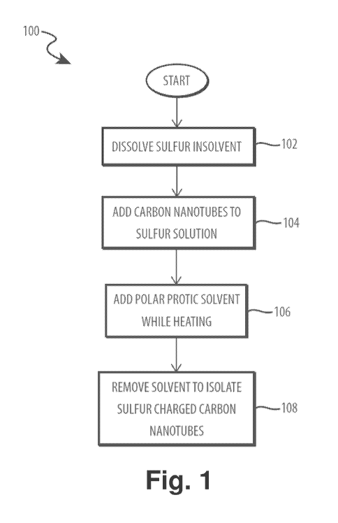
[0032] Turning now to the figures, Fig. 1 is a method, generally
designated 100,
depicting operational steps for producing sulfur charged carbon nanotubes. In
operation 102,
sulfur is dissolved in a solvent. In various embodiments, the sulfur may be
sublimed
elemental sulfur. The solvent may be any suitable solvent. In one embodiment,
the solvent is
carbon disulfide (CS2). In various embodiments, the amount of sulfur may be
determined
based on the amount of solvent and the amount of sulfur charged carbon
nanotubes desired.
For example, the sulfur may be approximately 50%wt ¨ 98%wt of the combined
sulfur-
nanotube mixture. In certain embodiments, one gram of sublimed sulfur may be
added for
every five ml of CS2. Those skilled in the art will appreciate that different
combinations are
possible so long as the sulfur is completely dissolved in the solvent. The
sulfur and solvent
may be stirred, sonicated, and/or heated in order to increase the solubility
of the sulfur in the
solvent and/or ensure even dispersion of the sulfur in the solution. In
certain embodiments,
the solution may be heated to 32 -33 C while stirring.
[0033] In operation 104, carbon nanotubes are added to the sulfur
solution. The
quantity of carbon nanotubes may be depend on the desired final composition of
the sulfur
4
CA 02949100 2016-11-14
WO 2015/176028 PCT/US2015/031234
charged carbon nanotubes. In various embodiments, the amount of nanotubes may
be
approximately 2%wt-50%wt of the combined sulfur-nanotube mixture. In various
embodiments, the carbon nanotubes may be any of single wall, soluble wall,
and/or multiwall
nanotubes. In some embodiments, the nanotubes are less than 10 nnn in
diameter. In some
embodiments, the nanotubes are less than 5 pm in length. In other embodiments,
the
nanotubes are less than 3 pm in length. In various embodiments, reducing the
length of the
nanotubes can reduce bundling of the nanotubes and provide more even coatings
when
applied to an electrode material. The type of carbon nanotube may be selected
based on the
desired electrical properties of the resulting cathode. The mixture containing
the sulfur,
solvent, and nanotubes may be sonicated and/or stirred to evenly disperse the
carbon
nanotubes in the mixture. By first dissolving the sulfur in the solvent, the
carbon nanotubes
are filled with sulfur by nanocapillary action. Capillary action is the
ability of a liquid to fill a
narrow space without (or in contravention of) external forces working on the
liquid (e.g.,
gravity). In small diameter tubes, such as carbon nanotubes, capillary action
results from
intermolecular forces within the liquid (e.g. surface tension) and adhesive
forces between the
liquid and the nanotube.
[0034] In operation 106, a polar protic solvent is added while heating
the sulfur-nanotube
mixture. In various embodiments, the polar protic solvent may be methanol,
isopropyl
alcohol, ethanol, and distilled water. In certain embodiments, the polar
protic solvent may be
added at a controlled rate (e.g., drops at a rate of 1 ml/min). The sulfur-
nanotube mixture
may be stirred and/or heated while adding the polar protic solvent. For
example, the mixture
may be heated to a temperature of 33 -35 C. By varying the rate at which the
polar protic
solvent is added to the solution, the size of sulfur particles may be
controlled. Additionally,
the polar protic solvent may facilitate a pi bond between sulfur particles and
the carbon
nanotubes, allowing sulfur to bond to the outside of the nanotubes in addition
to filling the
nanotubes via the nanocapillary action described above. By attaching sulfur to
the outside of
the carbon nanotubes, the cyclability and capacity of a resulting Li-S battery
may be
increased.
[0035] In operation 108, the solvent (i.e., the solvent described above
with respect to
operation 102) is removed to isolate the sulfur-carbon nanotube product. The
solvent may be
removed by any means that does not damage the sulfur-carbon nanotube product.
In certain
embodiments, the sulfur-carbon nanotube mixture may be heated (e.g., to 35 C)
to
evaporate a portion of the solvent until a moist mixture remains. The
remaining moist mixture
may be spread on a tray to air dry and allow any remaining solvent to
evaporate. A two-
stage drying process, as described herein, may help the resulting sulfur-
carbon nanotube
product maintain a particulate form, which can facilitate later processing
steps. In certain
embodiments, the resulting sulfur-carbon nanotube product may be ground into
fine particles
5
CA 02949100 2016-11-14
WO 2015/176028
PCT/US2015/031234
to facilitate later processing steps. In various embodiments, the evaporated
solvent may be
captured and reused in future processes, thereby reducing unusable byproducts
produced in
fabricating sulfur charged nanotubes. The embodiment of Fig. 1 produces
particulate sulfur-
charged nanotubes with sulfur filling the carbon nanotubes and attached to the
exterior of
the nanotubes. The structure of the resulting sulfur charged carbon nanotubes
is described
in further detail below with respect to Figs. 3 and 4.
[0036] Fig. 2 is a method, generally designated 200, depicting
operational steps for
producing a sulfur charged carbon nanotube cathode for use in a lithium ion
battery. The
embodiment of Fig. 2 provides a process by which Li-S cathodes may be produced
using
sulfur charged carbon nanotubes, such as those described above with respect to
Fig. 1.
[0037] In operation 202, a slurry is prepared with a sulfur charged
carbon nanotubes.
The slurry may include, for example, a binding agent, such as
poly(acrylonitrile-methyl
methacrylate), a conductive carbon additive, and a solvent, such as N-
methylpyrrolidinone.
The binding agent may adhere the sulfur charged carbon nanotubes to one
another. The
conductive carbon additive may increase the conductivity of the resulting
cathode. The
solvent may be used to achieve a desirable viscosity of the slurry to ease the
manufacturing
product and ensure an even coating of the sulfur charged carbon nanotubes on
the cathode.
[0038] In operation 204, an aluminum electrode is coated with the
slurry. In various
embodiments, the aluminum electrode may be a sheet of aluminum foil. The
slurry coating
may have a thickness of approximately 20-50 pm. The binding agent described
above with
respect to operation 202 may also act to bind the slurry to the aluminum
electrode. The
coated electrode may optionally be compressed using a roll press to achieve a
desired
thickness of the slurry coating. Those skilled in the art will appreciate that
varying the
thickness of the slurry, and, therefore, the layer of sulfur charged carbon
nanotubes, the
properties of the resulting cathode may be adjusted. For example, increasing
the thickness
of the sulfur charged carbon nanotubes may increase the amount of lithium that
may
penetrate the cathode. In operation 206, the solvent (i.e., the solvent added
in operation
202) is evaporated from the cathode. The solvent may be evaporated using any
appropriate
mechanism. In one embodiment, the aluminum electrode with slurry coating are
placed in an
oven and heated to a temperature of approximately 60 C for a sufficient amount
of time to
evaporate substantially all of the solvent from the slurry. In operation 208,
cathodes may be
cut to shape from the sulfur charged carbon nanotube coated aluminum
electrode. For
example, cathodes may be cut to shape for use in button (coin) cells, pouch
cells, etc.
[0039] The cathodes produced according to the method of Fig. 2 may be
used in a Li-S
battery having a silicon and/or germanium anode and an electrolyte to
facilitate lithium
shuttling. The electrolyte may include Lithium nitrate (LiNO3, N-Diethyl-N-
methyl-N-(2-
nnethoxyethyl)ammoniunn bis(trifluoromethanesulfonyl)imide (DEMMOX), dimethyl
ether
6
CA 02949100 2016-11-14
WO 2015/176028 PCT/US2015/031234
(DME) and 1,3-dioxolane (DOL). For example, the electrolyte may include 0.25E3
mol g-1 of
L1NO3 (L1NO3 = 68.95 g m01-1), 0.25E3 mol g-1 of DEMMOX (DEMMOX = 466.4 g me),
and
a 1:1 (wt.) mixture of DME and DOL.
[0040] Fig. 3 is a sulfur charged carbon nanotube cathode, generally
designated 300,
according to the embodiment of Fig. 2. The cathode 300 may include a plurality
of sulfur
charged carbon nanotubes 302. In various embodiments, the sulfur charged
carbon
nanotubes may coat an electrode material, such as aluminum in a substantially
even layer of
between approximately 20-50 pm. The sulfur charged carbon nanotubes provide a
cathode
with the energy density of a Li-S battery, while containing the sulfur
particles and preventing
polysulfides from bridging the gap between the cathode and anode to short the
battery.
[0041] Fig. 4 depicts the sulfur charged carbon nanotube 302. The sulfur
charged
carbon nanotube 302 includes a carbon nanotube 402 and a plurality of sulfur
particles 404
attached to the outside of the carbon nanotube 402. In various embodiments,
the carbon
nanotube 402 may also be filled with sulfur particles 404. As discussed above
with respect to
Fig. 1, the size of the sulfur particles may be controlled based on the rate
at which the polar
protic solvent is added to the sulfur-carbon nanotube mixture. In the depicted
embodiment,
the sulfur particles are approximately 30-35 nm in diameter, and the carbon
nanotube 402
charged with internal sulfur particles is approximately 45-50nnn in diameter.
Those skilled in
the art will appreciate that other sizes of sulfur particles 404 and carbon
nanotubes 402 are
possible. In various embodiments, the carbon nanotube 402 may be porous (e.g.,
the sulfur
in the carbon nanotubes stretches the carbon bonds creating "holes" in the
carbon
nanotubes), allowing for Li-ion diffusion during charging/discharging cycles.
[0042] Turning now to Figs. 5 and 6, Fig. 5 is a schematic view of a
half-cell cathode,
generally designated 500, for use in a coin cell. Fig. 6 is a method,
generally designated
600 for assembling a half-cell cathode in accordance with the embodiment of
Fig. 5. The
half-cell cathode may include a cell base 502, a sulfur charged carbon
nanotube cathode
504, one or more separators 506a/b, lithium foil 508, one or more spacers
510a/b, a biasing
device 512, and a cell cover 514.
[0043] In step 602, an electrolyte 516a is provided to the cell base
502. The electrolyte
may be, for example, 0.25E3 mol g-1 of L1NO3 (L1NO3 = 68.95 g 0.25E3 mol g-
1 of
DEMMOX (DEMMOX = 466.4 g moll, and a 1:1 (wt.) mixture of DME and DOL. In one
embodiment, 25 pL of the electrolyte 516a is provided to the center of the
cell base 502. In
step 604, the sulfur charged carbon nanotube cathode 504 is placed into the
electrolyte 516a. In various embodiments, the cathode is placed with the
aluminum contact
of the cathode 504 toward the cell base 502 and the sulfur charged carbon
nanotube coated
side away from the cell base 502. In step 606, additional electrolyte 516b is
provided on top
7
CA 02949100 2016-11-14
WO 2015/176028
PCT/US2015/031234
of the sulfur charged carbon nanotube side of the cathode 504. In one
embodiment 25 pL of
electrolyte 516b is provided on top of the cathode 504.
[0044] In step 608, a first separator 506a is placed on top of the
electrolyte solution and
the cathode 504. In various embodiments, the first separator 506a may have a
diameter
commensurate with the diameter of the cathode 504. In certain embodiments, the
first
separator 506a may be a 19 mm polypropylene separator. In step 610, additional
electrolyte 516c is provided on top of the first separator 506a. In one
embodiment 25 pL of
electrolyte 516c is provided on top of the first separator 506a. In step 612,
a second
separator 506b is placed on top of the electrolyte solution 516c and the first
separator 506a.
In various embodiments, the second separator 506b may have a diameter
commensurate
with the diameter of the first separator 506a. In certain embodiments, the
second separator
506b may be a 19 mm polypropylene separator. In step 614, additional
electrolyte 516d is
provided on top of the second separator 506b. In one embodiment 25 pL of
electrolyte 516d
is provided on top of the second separator 506b.
[0045] In step 616, a disc of lithium foil 508, that is at least as large
as the cathode
diameter, is centered and placed on the electrolyte 516d on the second
separator 506b. In
various embodiments, the disc of lithium foil 508 may completely cover the
cathode 504. In
step 618, the one or more spacers 510a/b are placed on top of the lithium foil
508. In various
embodiments, the spacers 510a/b may be stainless steel spacers. In various
embodiments,
two spacers 510a/b are placed on the lithium foil 508. In step 620, the
biasing device 512 is
placed on top of the spacers 510a/b. In various embodiments, the biasing
device 512 may
be a spring washer. In other embodiments, the biasing device 512 may be any
other type of
biasing device that does not interfere with the electrical properties of the
half-cell cathode
500. In step 622, the cell cover 514 is placed over the cell base 502 to
enclose the contents
of the half-cell cathode 500. In various embodiments, enclosing the half-cell
cathode 500
may cause electrolyte to leak from the half-cell cathode 500. Any electrolyte
may be
removed from the outside of the half-cell cathode 500. In step 624, the cell
cover 514 and
the cell base 502 are sealed together to create a complete half-cell cathode
500. The half-
cell cathode 500 may be used to make a full coin cell as described in further
detail below
with respect to Figs. 15 and 16.
Lithium Ion-Intercalated Nanocrystal Anodes
[0046] Silicon and germanium crystals can theoretically accommodate
large numbers of
lithium ions. The atomic ratio of Li atoms that can be utilized by Si or Ge
atoms is 4.4: 1.
(or 22 Li : 5 Si or Ge). Lithium ions are small enough to fit in between the
spaces of the
atoms making up a silicon or germanium crystal lattice. Further, germanium is
inherently
able to accept lithium ions at a faster rate than other proposed anode
materials this has
8
CA 02949100 2016-11-14
WO 2015/176028 PCT/US2015/031234
been empirically verified with test data. Lithium-ion diffusivity into Ge is
400 times faster
than silicon and nearly 1000 times faster than standard Li-ion technology.
[0047] Fig. 7A is a micrograph of a group of germanium nanocrystals 702
in a pure
state. A further magnified image of pure germanium nanocrystals is shown in
Fig. 7B. The
general form is highly spherical, indicating a high quality, uniform crystal
formation conducive
to maximizing the diffusive packing of lithium ions. Further, the surface
morphology
indicates a number of distended protrusions 706 on each of the nanocrystals
704. This
morphology translates into a significantly larger surface area for germanium
nanocrystals as
compared to silicon or other similar nanoscale crystal structures. The greater
surface area is
advantageous to promoting more rapid diffusion of lithium ions into the
crystal lattice during
recharge cycles. In fact, the cnductivity of Ge is 10,000 times higher than
that of Si, and the
diffusivity of Li ion in Ge is 400 times faster than that of Si at room
temperature, i.e., the
recharge rate for Ge is 400 times faster than the recharge rate for Si.
[0048] Fig. 7C depicts a micrograph of group of lithiated germanium
nanocrystals 708
similar in scale to the pure nanocrystals 702 of Fig. 7A. Comparison of the
morphology of
the pure nanocrystals 702 to the lithiated nanocrystals 708 indicates the
expansion of the
crystal lattice to accept the high ratio of lithium ions. In particular, the
lithiated germanium
nanocrystals 708 exhibit a nanoporous structure caused by the expansion of the
nanocrystal
lattice to accommodate the lithium ion intercalation. For high quality
(spherically uniform) Ge
nanocrystals, the expansion is isotropic, which minimizes strain on the
crystal lattice
structure and allows for very high cycle rates and minimizes irreversible
capacity loss.
Conversely, large nanocrystals of silicon typically expand anisotropically and
therefore are
subject to rapid capacity loss after only several cycles. However, if the Si
nanocrystals are
formed small enough (i.e., <100 nm and preferably <50 nm) the crystal
structure is more
uniform and expansion behaves more isotropically, causing less stress on the
nanocrystal
structure and thus increasing the cycling capacity.
[0049] In a lithium ion battery, the lithium source needs to be in the
anode or the
cathode; it cannot be in both. A charged battery contains all of the lithium
in the anode.
Commercially available batteries typically have all of the lithium stored in
the cathode in the
form of a lithium metal oxide, i.e., lithium cobalt oxide or lithium manganese
oxide or similar.
At the end of the manufacturing process for Li-ion batteries, all of the
batteries have to be
cycled at least once for the lithium to be inserted into the anode so that the
battery is already
charged when a consumer purchases it in a store. Lithium-metal-oxide cathodes
have very
limited capacity, on the order of 200-300 mAh/g at best.
[0050] If an anode, such as germanium, has an energy capacity of 1000mAh/g,
it cannot
be effectively paired with commercially available cathodes. Because of the
diffusion limits of
lithium, one cannot simply add 4-5 times as much cathode material to
compensate for an
9
CA 02949100 2016-11-14
WO 2015/176028 PCT/US2015/031234
equal volume of anode material. In view of this dilemma, the present
disclosure describes
cost effective processes for the creation prelithiated, high energy density
anode materials for
pairing with practical and low cost cathode materials (e.g., sulfur) that will
readily accept the
lithium stored in the anode. The anode of the full battery cell thus has
lithium already
combined/contained within the silicon or germanium nanocrystals, alleviating
the need for a
lithium compound cathode and an initial cycle to charge the battery for first
use.
[0051] In exemplary embodiments, the anodes described herein may
comprise
nanocrystal ("NC") structures of silicon (Si), germanium (Ge), or silicon-
germanium (SiGe)
described herein intercalated with lithium ions (Li+) (sometimes abbreviated
herein "Li-
SiNC," "Li-GeNC," and "Li-SiGeNC," respectively), and any combination thereof.
As used
herein, the terms "intercalation" or "diffusion" or "alloy" when referring to
lithium intercalation
into SiNC, GeNC, and/or SiGeNC as described herein refers to both
intercalation into the
crystal lattice of discrete nanocrystals and intercalation between
nanocrystals. These
lithiated nanocrystals are then bound to a conductive substrate to form a
structurally viable
anode. In the exemplary anode structures and manufacturing processes described
herein,
the nanocrystals need to be of "high quality" in order to achieve the
significant anode
lithiation results disclosed herein. "High quality" in the case of Si and Ge
nanocrystals for
use in lithium-ion battery anodes means below that Si nanocrystals have
diameters of less
than 150 nm and are substantially spherical in shape and that Ge nanocrystals
have
diameters less than 500nm and are substantially spherical in shape. The
smaller the
diameter of the nanocrystal, the greater the packing factor in the film, thus
resulting in
greater energy density. A higher packing factor can be achieved with bimodal
and trimodal
distributions e.g., 50 nm, 17 nm, 6.5 nm nanocrystal size distributions.
[0052] In some embodiments, cells, batteries, and similar devices
described herein may
comprise unstrained SiGeNC and/or GeNC. In some embodiments, the batteries and
similar
devices described herein may comprise strained SiGeNC and/or strained GeNC. As
used
herein, the terms "strained SiGeNC" and "strained GeNC" refers to SiGeNC
and/or GeNC
having a strained crystal structure, which is marked by a shift in a crystal
plane when
analyzed by x-ray diffraction. Strained SiGeNC and GeNC referenced herein may,
in some
embodiments, have a 20 value for the (111) crystal plane shifted relative the
(111) crystal
plane of bulk silicon from a lower limit of about 10, 2 , or 3 , or 4 to an
upper limit of about
80, 70, 6.,
or 4 . The shift may range from any lower limit to any upper limit and
encompass any subset therebetween.
[0053] Unless otherwise specified, the terms "SiGeNC" and "GeNC"
encompass both
unstrained and strained structures thereof. Further, as described herein, the
SiGeNC and
GeNC having the various properties and/or characteristics described herein
(e.g., 20 value
shift, average diameter, and the like) may be used to produce Li-SiGeNC and Li-
GeNC,
CA 02949100 2016-11-14
WO 2015/176028 PCT/US2015/031234
respectively. As such, it should be understood that the properties of the
SiGeNC and GeNC
described herein may extend to the Li-SiGeNC and Li-GeNC described herein.
[0054] In some embodiments, the SiGeNC described herein may comprise a
mole ratio
of silicon to germanium that ranges from a lower limit of about 1:10, 1:5, or
1:1 to an upper
limit of about 10:1, 5:1, or 1:1, and wherein the mole ratio may range from
any lower limit to
any upper limit and encompasses any subset therebetween.
[0055] In some embodiments, the SiNC, SiGeNC, and/or GeNC described
herein may
be p-doped or n-doped. In some embodiments, the SiGeNC may be in a "core-
shell"
configuration with a germanium lattice core surrounded by a silicon lattice
shell. In some
embodiments, the SiGeNC may merely be a combination or mixture of separate
SiNCs and
GeNCs.
[0056] In some embodiments, the SiNC, SiGeNC, and/or GeNC described
herein may
have an average diameter in at least one dimension ranging from a lower limit
of about 3
nm, 5 nm, 10 nm, 25 nm, or 100 nm to an upper limit of about 1000 nm, 500 nm,
250 nm,
150 nm, 100 nm, or 50 nm. The average diameter in at least one dimension may
range from
any lower limit to any upper limit and encompasses any subset therebetween. In
particular,
SiNC may be under 150nm diameter and preferably under 50 nm. Germanium
nanocrystals
may be under 1000 nm in diameter and preferably under 100 nm. Above these
diameters
the, nanocrystals may not maintain long range order after several lithiation-
delithiation cycles
and the materials become amorphous.
[0057] In some embodiments, the SiNC, SiGeNC, and/or GeNC described
herein may
have a narrow diameter distribution such that the standard deviation from the
average
diameter ranges from a lower limit of about 0.5 nm, 1 nm, or 2 nm to an
upper limit of
about 10 nm, 7 nm, or 5 nm. The standard deviation may range from any lower
limit to any
upper limit and encompasses any subset therebetween.
[0058] In some embodiments, the SiNC, SiGeNC, and/or GeNC described
herein may
have a multimodal diameter distribution (e.g., bimodal, trimodal, and so on).
It is desirable to
have a range of sizes from as-small-as-possible to the upper limits of SiNC
and GeNC noted
above in order to increase the packing density of the nanocrystals on a
conducting anode
substrate and thus maximize the diffusion density of lithium ions within and
between the
nanocrystals. An example of a self-organizing bimodal distribution 800 of two
different sizes
of germanium nanocrystals is depicted in the micrograph of Fig. 8. As shown,
the
larger-sized nanocrystals 802 (e.g., 50 nm diameter) arrange to form a base
layer on a
substrate while the smaller-sized nanocrystals 804 (e.g., 12 nm diameter)
arrange in the
spacing between the larger-sized nanocrystals 802. In this way, the density of
the
nanocrystals is increased.
11
CA 02949100 2016-11-14
WO 2015/176028 PCT/US2015/031234
[0059] In exemplary embodiments, the SiGeNC and/or GeNC described herein
having a
multimodal diameter distribution may have at least one mode with an average
diameter in at
least one dimension ranging from a lower limit of about 4 nm, 7 nm, 12 nm, or
25 nm to an
upper limit of about 250 nm, 150 nm, 100 nm, or 50 nm. The average diameter in
at least
one dimension may range from any lower limit to any upper limit and
encompasses any
subset therebetween. In some embodiments, the modes of a multimodal diameter
distribution of the SiNC, SiGeNC, and/or GeNC described herein may
independently have a
narrow diameter distribution such that the standard deviation for each mode
independently
ranges from a lower limit of about 0.5 nm, 1 nm, or 2 nm to an upper limit
of about 10
nm, 7 nm, or 5 nm. The standard deviation may range from any lower limit to
any upper limit
and encompasses any subset therebetween.
[0060] In some embodiments, the Li-SiGeNC and Li-GeNC described herein
may have a
mole ratio of Li to SiGe (i.e., the combined moles of Si and Ge) or Li to Ge,
respectively,
ranging from a lower limit of greater than 0, about 0.2, 0.5, 1, 1.5, or 2 to
an upper limit of
about 3.6, 3.5, 3.25, 3, 2.5, 2, or 1.5. The mole ratio of Li to SiGe or Li to
Ge may range
from any lower limit to any upper limit and encompasses any subset
therebetween. It should
be noted that such mole ratios are described in terms of a fully charged
battery or other
similar device. The mole ratio of Li to SiGe or Li to Ge may depend on, inter
alia, the ratio of
the lithium source to the SiGeNC and/or GeNC in the synthesis of the Li-SiGeNC
and/or Li-
GeNC.
[0061] In some embodiments, lithium intercalation may be effected at
least one of:
mixing the SiGeNC and/or GeNC with lithium metal (e.g., folding the two
together and
allowing the lithium to intercalate), mixing the SiGeNC and/or GeNC with
lithium metal in the
presence of an ionic liquid, electrodepositing the SiGeNC and/or GeNC on
lithium metal
electrode, and the like. In some embodiments, the ionic liquid and
electrodeposition may be
used in combination.
[0062] In some exemplary implementations, elemental lithium from a
lithium metal
electrode intercalates into the SiNC, SiGeNC, and/or GeNC attracted to the
surface thereof
such that a paste of lithiated nanocrystals and ionic liquid forms on the
lithium metal
electrode. The paste has a dark-brown to purple-black color depending on the
amount of
lithium present. It has been observed that the paste of Li-SiGeNC and/or Li-
GeNC is stable
in air for extended periods of time and may be exposed to water without
reaction unlike
lithium metal. The intercalation of the lithium ions within the nanocrystal
structures protects
the lithium from interaction with air and moisture. Further, in the case of
GeNCs, germanium
does not form surface oxides in air like silicon, which further improves the
diffusion speed of
lithium ions.
12
CA 02949100 2016-11-14
WO 2015/176028 PCT/US2015/031234
[0063] Once formed, the lithiated nanocrystal paste may be used in
further anode
manufacturing processes without need for a protective environment (e.g., an
argon-filled
enclosure), which can significantly reduce the cost and difficulty of the
process. Further, the
nonvolatile paste may advantageously enable batteries and similar devices with
minimal to
no risk of fire in the event of battery damage that exposes the anode to air
or water. Such
an advantage and risk mitigation may be exploited in the production of lighter-
weight
batteries because the battery casings may be made of different materials,
which may be
useful in electric vehicles where much of the battery weight can be attributed
to protection
from puncture in crashes.
[0064] In some embodiments, the anode may comprise a conductive support
having a
film disposed thereon, the film comprising the nanocrystals described herein.
Examples of
the conductive supports may include, but are not limited to, silicon,
germanium, graphite,
nickel, iron, stainless steel, aluminum, copper, and the like, and any
combination thereof. In
some embodiments, the conductive support may be in a form that is at least one
of the
following: a sheet, a foil, a grid, a rod, and the like, and any hybrid
thereof, which may, inter
alia, depend on the configuration of the battery or other device in which the
anode is to be
used.
[0065] In some embodiments, the film may consist essentially of the
nanocrystals
described herein. In other embodiments, the film may comprise the nanocrystals
described
herein and optionally further comprise binders and/or existing anode
materials. These
optional components may be used to achieve the desired physical
characteristics of the film
and/or the precursor thereof. Examples of physical characteristics may
include, but are not
limited to, the rheology of the film precursor, the drying characteristics of
the film precursor,
the film plasticity, the film conductivity, the adhesion strength of the film
to the conductive
support, and the like, and any combination thereof.
[0066] In some embodiments, binders may be useful in achieving the
desired physical
characteristics of an anode film or precursor thereof by adhering the
nanocrystals together or
to a conductive support. The binders may minimally, if at all, impact the
electrochemistry of
the resultant battery or similar device in which the anode is used. Binders
may be
conductive or insulating. Examples of binders may include, but are not limited
to,
polyvinylidene fluoride, N-methyl-2-pyrrolidone, carboxymethyl cellulose,
agar, styrene-
butadiene rubber, polytetrafluoroethylene, conductive acetylene black,
conductive graphite
powders, and the like, and any combination thereof. In some embodiments, the
binder may
be selected to enable a hydrogel or organogel film (e.g., crosslinked agar or
carboxymethyl
cellulose). In some embodiments, the binder may be selected to enable a
printable film
precursor that dries like ink (e.g., conductive graphite powder). In some
embodiments, the
13
CA 02949100 2016-11-14
WO 2015/176028 PCT/US2015/031234
binder may be selected to enable a flexible, dry film (e.g., styrene-butadiene
rubber or
polytetrafluoroethylene).
[0067] Existing anode materials may be useful in achieving the desired
physical
characteristics of the film or precursor thereof and may participate in the
electrochemistry of
the resultant battery or similar device in which the anode is used. In some
embodiments, the
use of existing anode materials may be minimized or eliminated because they
provide little
to no enhancement to the anode properties and occupy volume that could
otherwise be filled
by nanocrystals described herein. Examples of existing anode materials may
include, but
are not limited to, graphite powder, carbon nnicrobeads, Li4Ti5012, LiVP04F,
and the like, and
any combination thereof.
[0068] The concentration of the various components in the film precursor
may be at
levels necessary to achieve the desired physical characteristics of the film
and/or the
precursor thereof and the desired electrochemical characteristics of the
anode, which may
allow for each of the component concentration to vary between about 0% and
about 99% by
weight of the film precursor.
[0069] In some embodiments, the film precursor may be a paste. For
example, a film
precursor may be the paste described above that is produced during at least
some
embodiments of the synthesis of Li-SiNC, Li-SiGeNC, and/or Li-GeNC. In another
example,
a paste film precursor may be a paste of SiGeNC, graphite, and polyvinylidene
fluoride in N-
methyl-2-pyrrolidone. In some embodiments, the anode may comprise a fast ion
conductor
layer (e.g., lithium nitride or the like) between the conductive support and
the film.
[0070] In some embodiments, the film precursor may be a less viscous
liquid, which may
be a diluted paste or formed independently. In some embodiments, lower
viscosities may be
achieved with the use of organic solvents (e.g., benzene, methanol, and the
like). In some
embodiments, the film precursor may be at a viscosity that enables deposition
onto the
conductive substrate by methods like electrodeposition, spraying, painting,
dip coating,
calendaring, and the like. Such methods may advantageously enable scaling the
production
of anodes described herein to industrial production levels, e.g., using
coating methods
similar to that used in the semiconductor industry or using printing methods
in producing
flexible batteries or similar devices.
[0071] In some embodiments, after deposition onto a conductive
substrate, the film
precursor may be dried to yield the film that comprises the pre-lithiated
nanocrystals
described herein (e.g., between about 30 C and about 220 C depending on the
composition
of the film precursor). In some embodiments, after deposition onto the
conductive substrate,
the film precursor may be allowed to set to yield a hydrogel or organogel film
that comprises
the pre-lithiated nanocrystals described herein.
14
CA 02949100 2016-11-14
WO 2015/176028
PCT/US2015/031234
[0072] The diffusion limit of lithium into a SiNC, SiGeNC, or GeNC
deposition coating is
typically between 30-40 microns. Therefore, in some embodiments, the thickness
of the film
comprising the nanoparticles described herein may have a thickness ranging
from a lower
limit of about 10 microns, 25 microns, or 100 microns to an upper limit of
about 500 microns,
250 microns, or 100 microns. The thickness may range from any lower limit to
any upper
limit and encompasses any subset therebetween.
[0073] Fig. 9 is a flowchart depicting a general electrodeposition
process 900 for
preparing a pre-lithiated nanocrystal paste for use in anode construction. In
step 902,
SiNCs, SiGeNCs, and/or GeNCs are mixed into a solution of an ionic fluid(s), a
nonaqueous
solvent(s), or a combination of both to form a colloidal suspension of the
nanocrystals. A
lithium metal ribbon is positioned in the colloidal mixture as an anode
electrode as indicated
in step 904. Similarly, a carbon electrode is placed into the colloidal
mixture as a cathode as
provided in step 906. A voltage is then applied across the anode and cathode
to drive the
nanocrystals from the mixture to coalesce on the lithium metal ribbon anode as
indicated in
step 908. Lithium ions from the lithium metal intercalate into the
nanocrystals deposited on
the lithium metal and the lithiated nanocrystals in the presence of the ionic
fluid and/or
solvent form a paste on the surface of the lithium metal ribbon. The lithium-
diffused
nanocrystal paste is then removed from the lithium metal anode as indicate in
step 910.
Finally, a prelithiated anode is formed by spreading or otherwise distributing
the paste over
an electrode, such as a fast ion conductor or a solid electrolyte, as
indicated in step 912.
[0074] Fig. 10 is a flowchart depicting a general electrolytic process
1000 for preparing a
pre-lithiated nanocrystal paste for use in anode construction. In step 1002,
SiNCs, SiGeNCs,
and/or GeNCs are mixed into a solution of an ionic fluid(s), a nonaqueous
solvent(s), or a
combination of both, plus a lithium electrolyte, to form a colloidal
suspension of the
nanocrystals. A first piece of lithium metal ribbon is connected to a positive
electrode as
provided in step 1004 and a second piece of lithium metal ribbon is connected
to a negative
electrode as provided in step 1006. Each of the first and second pieces of
lithium metal is
positioned in the colloidal mixture as indicated in step 1008 with care taken
to ensure
physical separation of the lithium metal electrodes as noted in step 1010. A
voltage is then
applied across thee electrodes to drive the nanocrystals from the mixture to
coalesce on the
lithium metal ribbon anode as indicated in step 1012. The voltage is
maintained until lithium
ions from the lithium metal ribbon intercalate into the deposited nanocrystals
and a paste of
lithiated nanocrystals and solvent forms on the surface of the lithium metal
ribbon as
provided in step 1014. The voltage source is then disconnected from the
electrodes and the
lithium-diffused nanocrystal paste is removed from the lithium metal ribbon as
indicated in
step 1016. The paste is then mixed with binder and/or conductive carbon under
ambient
conditions, i.e., in air at atmospheric pressure without additional safeguards
such as an inert
CA 02949100 2016-11-14
WO 2015/176028 PCT/US2015/031234
gas or low moisture environment, as indicated in step 1018. The paste and
binder mixture is
then spread or otherwise distributed on a conductive anode substrate as
provided in
step 1020. Finally, the binder is cured in order to adhere the lithiated
nanocrystal paste to
the anode substrate to complete formation of a prelithiated anode as indicated
in step 1022.
[0075] EXAMPLE 1: Anode Construction Via Electrodeposition - In accordance
with the
general method shown in Fig. 9 and described above, a high-energy capacity
anode for
lithium ion batteries may be formed via electrochemical super saturation of
lithium into
silicon, germanium, and silicon-germanium alloy nanoparticles. Silicon,
germanium, and/or
silicon-germanium alloy nanoparticles (Universal Nanotech Corporation), were
suspended
as a colloid in a mixture of an ionic fluid 1-butyl-3-methylimidazolium
thiocyanate (bmimSCN)
and a non-aqueous solvent dimethylacetamide. A 2/3" strip of Li metal ribbon
was used as
an anode and carbon electrode was used as a cathode. Each was connected to a
respective terminal of a voltage source and placed in the colloidal mixture.
Voltage in a
range of 250mV-5 V, typically 2-4V, was applied to drive a current through the
solution to
begin the Li intercalation into the nanocrystals.
[0076] The nanocrystals are driven to the Li metal anode. Visually, the
lithium ribbon
appears to "swell" and take on a reddish-orange-maroon color. This "swelling"
is a coating
of the lithiated nanocrystals on the decomposed lithium ribbon. The final
consistency of the
resulting product is a paste or gel-like consistency with lubricity provided
by the ionic
fluid/solvent mixture. An anode was formed by spreading the gel with a spatula
over a sheet
comprised of a fast ion conductor (e.g., solid electrolyte, such as lithium
nitride. The
nanocrystal anode paste on the fast ion conductor structure was then
sandwiched on top of
a cathode material (LiMn204). An aluminum electrode was attached to the
cathode (i.e.,
LiMn204) and a copper electrode was attached to the anode to form a battery.
The entire
structure was sealed in a protective nonconductive lamination sheet with
portions of the
aluminum and copper electrodes protruding outside the lamination sheet to
serve as
terminals for the battery.
[0077] EXAMPLE 2: SiGeNC Lithiation Using Ionic Fluid bmimSCN - In an
argon filled
environment (i.e., a glove box), two separate pieces of lithium metal foil
(each 2cm LX 1cm
W X 0.038cm t) were connected, respectively, to the negative and positive
electrodes of a
power supply. Si0.22Ge0.78NCs were dispersed into 1-butyl-3-methylimidazolium
thiocyanate (bmimSCN) and heated to 40 C under argon with constant stirring
in an
Erlenmeyer flask. The concentration of Si0.22Ge0.78NCs in the ionic fluid was
matched to
the lithium (1cm LX 1cm W X 0.038 cm t) such that nearly all the lithium was
absorbed by
the amount of GeNCs contained in the flask. For this experiment, 0.00288 mol
Li (1cm2) and
0.0160 mol of Si0.22Ge0.78NCs were used. The electrodes were placed directly
opposed
to each other 1cm apart with 1cm2 of the Li metal submerged into the
Si0.22Ge0.78NCs-
16
CA 02949100 2016-11-14
WO 2015/176028
PCT/US2015/031234
ionic fluid dispersion. A constant voltage 3V was used to drive the
Si0.22Ge0.78NCs to the
lithium metal on the positive electrode where the lithium subsequently
diffused into the
Si0.22Ge0.78NCs. The reaction was stopped after 25 minutes. The resultant
product was a
deep red paste comprised of the ionic fluid and lithiated Si0.22Ge0.78NCs.
[0078] EXAMPLE 3: Anode Construction Using Electrolyte LiTFSI. ¨ The
process of
Example 2 was altered to introduce an electrolyte, lithium
bis(trifluoromethanesulfonyl)imide
(LiTFSI) to make a 1M solution of LiTFSI in bmimSCN. The general method was
thus
changed to follow the process shown in Fig. 10 and described above.
Additionally, the
process was conducted at room temperature. In all other respects the
conditions were the
same. The addition of the lithium salt (LiTFSI) reduced the reaction time to
create the paste
from 25 minutes to 15 minutes.
[0079] EXAMPLE 4: Anode Construction Using Electrolyte LiPF6. - In
accordance with
the general method shown in Fig. 10 and described above, in an argon filled
environment
(e.g., in a glove box) at room temperature and atmospheric pressure, two
separate pieces of
lithium metal foil (each 2cm L X 1cm W X 0.038cm t) were connected,
respectively, to the
negative and positive electrodes of a power supply. High quality (spherically
symmetric)
germanium nanocrystals (<150 nm diameter) were dispersed into an electrolyte
of lithium
salt, i.e., lithium hexafluorophosphate (LiPF6) in a 1 : 1 ratio of ethylene
carbonate to diethyl
carbonate in an Erlenmeyer flask. The electrodes were placed directly opposed
to each
other 1cm apart with 1cm2 of the Li metal submerged into the GeNC-electrolyte
dispersion.
For this experiment, 0.00288 mol LiPF6 and 0.0127 mol of GeNCs were used. The
concentration of germanium nanocrystals in the electrolyte was matched to the
lithium (1cm
L X 1cm W X 0.038 cm t) such that nearly all the lithium is absorbed by the
amount of
germanium contained in the flask. A constant voltage 4V was used to drive the
germanium
nanocrystals to the lithium metal on the positive electrode where the lithium
diffused into the
GeNCs deposited onto the lithium foil. The reaction was stopped after 15
minutes. The
resultant product was a viscous dark purple-black paste comprised of
electrolyte and
lithiated GeNCs. The paste can then be mixed with a binder or conductive
carbon additive
and be deposited onto a conductive substrate for use as a lithium-ion battery
anode.
[0080] EXAMPLE 5: Anode Construction Using bmimSCN with Electrolyte L1PF6. -
The
process of Example 4 was altered to use 1-butyl-3-methylimidazolium
thiocyanate
(bmimSCN) as the ionic fluid in conjunction with lithium hexaflurophosphate
(LiPF6). In
other respects the apparatus, conditions, and techniques of Example 4 remained
the same
with the exception of a lower voltage of between 2V-4V held constant while the
electrochemical reaction occurred. A dark brown to purple black paste
comprised of
electrolyte and lithium loaded GeNCs formed on the lithium electrode. An anode
was
formed with the paste and it was combined with a cathode electrode in a manner
similar to
17
CA 02949100 2016-11-14
WO 2015/176028 PCT/US2015/031234
Example 1 to form a cell. Fig. 11 depicts a series of discharge/recharge
cycles 1100 for this
exemplary cell. The cell was tested for energy capacity and volumetric energy
density
according to standard Li-ion battery testing protocol. Each charge cycle 1102
had a charge
rate of C/10 and a discharge rate of 1C. The cell had a 98% Coulomb
efficiency, i.e., each
discharge cycle 1104 was consistently 98% of energy that was put in for the
charge.
[0081] Example 6: Half-cell Anode Constructed from Lithiated Nanocrystal
Material.
[0082] Germanium nanocrystals were mixed into a slurry with poly acrylic
acid binder
(PAA)-450, Super-P Li conductive additive (Timcal), and N-Methyl-pyrollidone.
The ratio of
Li-GeNC to conductive carbon to binder was 40:40:20. The mixture was bath
sonicated for
15 minutes and then spread with a doctor blade onto a copper foil current
collector. The
slurry coated copper electrode was then placed in an oven at 60 C to
evaporate the solvent
(N-Methyl-2-pyrollidone). After drying, the coated copper electrode was
calendered (roll
pressed) to achieve a film thickness of 10 pm. Discs with a diameter of 11mm
were
punched out of the paste coated copper electrode for half-cell assembly. The
resulting mass
loading was measured to be 2.98 mg/crn2 of Li-GeNC.
[0083] The half-cell was assembled in an argon filled glove box using a
2032 stainless
steel coin cell with a negative base and positive cap. A schematic diagram of
the
components of the half-cell anode 1200 in an exploded view is depicted in Fig.
12 and a
method 1300 for assembling the half-cell is presented in Fig. 13. Initially,
25 pL of
electrolyte 1204 is deposited at the center of the cell case base 1202 as
indicated in
step 1302. In this example, the electrolyte is 1M LiPF6 in fluoroethylene
carbonate (FEC)
(both from Aldrich) (<0.1 ppm 02). Next, the Cu / Li-GeNC anode 1206 is placed
onto the
electrolyte droplet 1204 in the center of the base 1202 with the anode Li-GeNC
paste-coated
side up and Cu side down as indicated in step 1304. Another 25 pL of
electrolyte 1208 is
then added to the center of the anode 1206 as indicated in step 1306. A 19mm
diameter
polypropylene separator 1210 (e.g., Celgard 2500 membrane separator at 25 p m
thickness), sized to cover the entire cell base 1202, was placed onto the
anode 1206 as
indicated in step 1308. Another 25 pL of electrolyte 1212 was then deposited
on the center
of the separator 1210 as indicated in step 1310. A second polypropylene
separator 1214
(also commensurate in size with the cell base 1202) was placed onto the first
separator 1210
over the electrolyte 1212 as indicated in step 1312. A further 25 pL of
electrolyte 1216 was
then added to the center of the second separator 1314.
[0084] A lithium foil disk 1218 of at least the same diameter as the
anode 1206 was
placed onto the center of the second separator 1214 to act as a
counter/reference electrode
as indicated in step 1316. A stack of two stainless steel spacers 1220, 1222
centered on the
cell base 1202 were placed onto the lithium foil disk 1218 as indicated in
step 1318. A
biasing device such as a spring washer 1224 was placed onto the spacer stack
1220, 1222
18
CA 02949100 2016-11-14
WO 2015/176028
PCT/US2015/031234
as indicated in step 1320. The cell cap 1226 is then placed over the spring
washer 1224 as
indicated in step 1322 and the cell cap 1226 and cell base 1202 are compressed
together to
encase the other components of the cell stack as indicated in step 1324. (Any
excess
electrolyte forced out when cell is compressed may be wiped off.) The cell cap
1226 and
cell base 1202 may then be sealed together as indicated in step 1326, for
example, by
placing the half-cell 1200 in a crimping tool with the cell base 1202 oriented
downward and
crimping and removing any excess fluid after crimping. The half-cell anode
1200 may be
used to make a full coin cell as described in further detail below with
respect to Figs. 15 and
16.
[0085] Once the half-cell 1200 was completed, an initial conditioning cycle
of C/20 using
1C = 1180 mAh/g and constant current for charge-discharge was run between
0.01V and 1V
vs. Li/Li+. Subsequent cycles were carried out at a rate of 1C. Fig. 14 shows
a graph 1400
of two sequential charge cycles 1402a/b and related discharge cycles 1404a/b
for the GeNC
anode half-cell 1200 of Example 6. Each of the charge cycles 1402a/b reaches a
specific
energy capacity of about 1080 nriAh/g from an original capacity of 1100 rnAh/g
after multiple
recharge cycles, thus indicating no breakdown in the charge capacity of the
anode as the
nanocrystals expand and contract with lithiation and delithiation.
[0086] Example 7: Anode Cycle Testing - A plurality of samples were
prepared by
electrodepositing GeNC on to glass coated with indium tin oxide. Using an
Agilent
Technologies 4155C Semiconductor Parameter Analyzer and two Alessi needle
probes in
contact with the sample, I-V curves were obtained, and Voc values of about 7
to about 14
were measured. Further, the charge-discharge rates observed were comparable to
other
technologies like bulk silicon or germanium.
Batteries and Similar Devices Comprising the Disclosed Cathodes and Anodes
[0087] In some embodiments, batteries and similar devices described herein
may
comprise an anode described herein that comprises the nanocrystals described
herein; a
cathode; a separator disposed between the cathode and the anode; and an
electrolyte. One
skilled in the art with the benefit of this disclosure should understand the
plurality of
configurations for such components to achieve a desired the battery and
similar device.
Examples of similar devices may include, but are not limited to, super-
capacitors, ultra-
capacitors, capacitors, dual in-line package batteries, flex batteries, large-
format batteries,
and the like.
[0088] Examples of cathode materials may, in some embodiments, include,
but are not
limited to, lithium cobalt oxide, lithium nickel oxide, lithium manganese
oxide, lithium iron
phosphate, lithium cobalt nickel manganese oxide, polypyrrole, polyaniline,
and the like, and
any combination thereof.
19
CA 02949100 2016-11-14
WO 2015/176028
PCT/US2015/031234
[0089] Examples of separators may, in some embodiments, include, but are
not limited
to, polyolefin-based separators, fluorinated polyolefin-based separators,
fluorine resin based
separators (e.g., polyethylene separators), polypropylene separators,
polyvinylidene fluoride
separators, VDF-HFP copolymer separators, polyethylene/polypropylene bilayer
separators,
polypropylene/polyethylene/polypropylene triple layer separators,
polyethylene/polypropylene/polyethylene triple layer separators, and the like,
any hybrid
thereof, and any combination thereof.
[0090] In some embodiments, the electrolyte of the half-cells,
batteries, and similar
devices described herein may be a traditional electrolyte, e.g., a lithium
salt in a non-
aqueous solvent optionally with a polymer or a solid electrolyte. Examples of
lithium salts
may include, but are not limited to, fluorine-containing inorganic lithium
salts (e.g., lithium
bis(trifluoromethanesulfonyl)imide (LiTFSI), LiPF6, and LiBF.4), chlorine-
containing inorganic
lithium salts (e.g., LiCI04), fluorine-containing organic lithium salts (e.g.,
LiN(CF3S02)2,
LiN(C2F5S02)2, LiCF3S03, LiC(CF3S02)3, LiPF4(CF3)2, LiPF4(C2F5)2,
LiPF4(CF4S02)2,
LiPF4(C2F5S02)2, LiBF2(CF3)2, LiBF2(C2F5)2, LiBF2(CF3S02)2, and
LiBF2(C2F5S02)2), and the
like, and any combination thereof. Examples of non-aqueous solvents may, in
some
embodiments, include, but are not limited to, 1-butyl-3-methylimidazolium
thiocyanate
(bmimSCN), N-butyl-N-nnethylpyrrolidiniunn
bis(trifluoronnethanesulfonyl)innide (Pyr14TFSI),
cyclic carbonates (e.g., ethylene carbonate and propylene carbonate), linear
carbonates
(e.g., dimethyl carbonate and ethylmethyl carbonate), cyclic carboxylic acid
esters (e.g., y-
butyrolactone and y-valerolactone), and the like, and any combination thereof.
Examples of
solid electrolytes may include, but are not limited to, polyethylene oxide
(PEO),
polyacrylnitrile (PAN), or polymethylnnethacrylate (PM MA), and the like, and
any combination
thereof. Examples of solid electrolytes (also known as fast ion conductors)
may, in some
embodiments, include, but are not limited to, lithium nitride, lithium iodide,
lithium phosphate,
and the like, and any combination thereof.
[0091] In some embodiments, the use of the nanocrystals described herein
may enable
the production of batteries and similar devices that can be cycled (i.e.,
charged and
discharged) a plurality of times (e.g., about 500 times or greater) with
minimal power density
loss.
[0092] In some embodiments, the use of the nanocrystals described herein
may enable
the production of batteries and similar devices that have a tailorable open
circuit voltage
(Voc), which may range from about 0.1 V to about 18 V including any subset
therebetween.
The Vc,c of the device may depend on, inter alia, the morphology and
composition of the
nanocrystals. Advantageously the Voc values that can be achieved be
advantageous in
producing higher voltage devices as bulk silicon and germanium have Voc levels
on the
order of about 0.4 V to about 1.1 V.
CA 02949100 2016-11-14
WO 2015/176028 PCT/US2015/031234
[0093] Example 9: Battery Cell with Li-GeNC Anode - A battery prototype
was produced
using an anode comprising Li-GeNCs. The anode measured an energy density per
area of
about 7.67 mWh/cm2 and a capacity per area of about 2.32 mAh/cm2, which were
used to
derive the anode energy density of about 38,350 Wh/L, an anode specific energy
of 13,456
Wh/kg, and an anode specific capacity of about 3,684 Ah/kg. Further, upon
several charge-
discharge cycles (greater than 20), the battery showed no measurable
degradation in
performance. Such a battery has been charged and retained the charge for two
to three
weeks with no measureable loss of charge.
[0094] Example 9: Battery Cell with Li-SiGeNC Anode - Another battery
prototype was
produced using an anode comprising lithium stored in SiGeNCs. The anode
measured an
energy density per area of about 3mAh/cm2. Further, upon several charge-
discharge cycles
(greater than 20), the battery showed no measurable degradation in
performance. Such a
battery has been charged and retained the charge for two to three weeks with
no
measureable loss of charge.
[0095] Example 10: Full Coin Cell Battery with Li-SiGeNC Anode and S-C
Nanotube
Cathode - Fig. 15 is a schematic view of full coin cell, generally designated
1500. Fig. 16 is
a method, generally designated 1600 for assembling a full coin cell in
accordance with the
embodiment of Fig. 15. The full coin cell may include a cell base 1502, a half-
cell cathode
1504, one or more separators 1506a/b, a half-cell anode 1508, one or more
spacers
1510a/b, a biasing device 1512, and a cell cover 1514.
[0096] In step 1602, an electrolyte 1516a is provided to the cell base
1502. The
electrolyte 1516a may be, for example, 0.25E3 mol g-1 of LiNO3 (LiNO3 = 68.95
g
0.25E3 mol g-1 of DEMMOX (DEMMOX = 466.4 g moll, and a 1:1 (wt.) mixture of
DME and
DOL. In one embodiment, 25 pL of the electrolyte 1516a is provided to the
center of the cell
base 1502. In step 1604, the half-cell cathode 1504 is placed into the
electrolyte 1516a. In
various embodiments, the half-cell cathode 1504 includes a sulfur charged
carbon nanotube
cathode as described above with respect to Figs. 1-6. In various embodiments,
the cathode
1504 is placed with the aluminum contact of the cathode 1504 toward the cell
base 1502 and
the sulfur charged carbon nanotube coated side away from the cell base 1502.
In step 1606,
additional electrolyte 1516b is provided on top of the half-cell cathode 1504.
In one
embodiment 25 pL of the electrolyte 1516b is provided on top of the half-cell
cathode 1504.
[0097] In step 1608, a first separator 1506a is placed on top of the
electrolyte solution
and the cathode 1504. In various embodiments, the first separator 1506a may
have a
diameter commensurate with the diameter of the cathode 1504. In certain
embodiments, the
first separator 1506a may be a 19 mm polypropylene separator. In step 1610,
additional
electrolyte 1516c is provided on top of the first separator 1506a. In one
embodiment 25 pL of
the electrolyte 1516c is provided on top of the first separator 1506a. In step
1612, a second
21
separator 1506b is placed on top of the electrolyte solution 1516c and the
first separator
1506a. In various embodiments, the second separator 1506b may have a diameter
commensurate with the diameter of the first separator 1506a. In certain
embodiments, the
second separator 1506b may be a 19 mm polypropylene separator. In step 1614,
additional
electrolyte 1516d is provided on top of the second separator 1506b. In one
embodiment 25
pL of the electrolyte 1516d is provided on top of the second separator 1506b.
[0098] In step 1616, a half-cell anode 1508, that is at least as large as
the cathode
diameter, is centered and placed on the electrolyte 1516d on the second
separator 1506b. In
various embodiments, the half-cell anode 1508 may completely cover the cathode
1504. In
certain embodiments, the half-cell anode 1508 may be produced as described
above with
respect to Figs. 12 and 13. In step 1618, the one or more spacers 1510a/b are
placed on
top of the half-cell anode 1508. In various embodiments, the spacers 1510a/b
may be
stainless steel spacers. In various embodiments, two spacers 1510a/b are
placed on the
half-cell anode 1508. In step 1620, the biasing device 1512 is placed on top
of the spacers
1510a/b. In various embodiments, the biasing device 1512 may be a spring
washer. In other
embodiments, the biasing device 1512 may be any other type of biasing device
that does not
interfere with the electrical properties of the full coin cell 1500. In step
1622, the cell cover
1514 is placed over the cell base 1502 to enclose the contents of the full
coin cell 1500. In
various embodiments, enclosing the full coin cell 1500 may cause electrolyte
to leak from the
full coin cell 1500. Any electrolyte may be removed from the outside of the
full coin cell 1500.
In step 1624, the cell cover 1514 and the cell base 1502 are sealed together
to create a
complete full coin cell 1500.
[0099] The particular embodiments disclosed above are illustrative only,
and may be
modified and practiced in different but equivalent manners apparent in view of
the teachings
herein. It is therefore evident that the particular illustrative embodiments
disclosed above
may be altered, combined, or modified and all such variations are considered
within the
scope and spirit of the present invention. The invention illustratively
disclosed herein
suitably may be practiced in the absence of any element that is not
specifically disclosed
herein and/or any optional element disclosed herein. All numbers and ranges
disclosed
above may vary by some amount. Whenever a numerical range with a lower limit
and an
upper limit is disclosed, any number and any included range falling within the
range is
specifically disclosed. In particular, every range of values (of the form,
"from about a to about
b," or, equivalently, "from approximately a to b," or, equivalently, "from
approximately a-b")
disclosed herein is to be understood to set forth every number and range
encompassed
within the broader range of values.
22
CA 2949100 2018-06-28
,
[00100] The above specification, examples and data provide a complete
description of
the structures, methods, and use of exemplary embodiments of the invention as
defined
herein. Although various embodiments of the invention have been described
above with a
certain degree of particularity, or with reference to one or more individual
embodiments,
those skilled in the art could make numerous alterations to the disclosed
embodiments
without departing from the scope of the invention. Other embodiments are
therefore
contemplated. Changes in detail or structure may be made without departing
from the basic
elements of the invention as defined herein.
23
CA 2949100 2018-06-28