Note: Descriptions are shown in the official language in which they were submitted.
81800904
MAGNETIC BATTERY CHARGING SYSTEM FOR STYLUS
BACKGROUND
[0001] Touch-sensitive display devices, track pads, writing tablets,
graphics
tablets/digitizers, and other electronic devices may accept input from an
input device, such as a
stylus. A stylus may be more suitable for precision tasks, such as drawing,
writing, selecting
icons, etc., than a finger or other blunt input mechanism. A stylus may
include
transmission/receiving devices and/or otherwise be capable of performing
active functions to
interact with a computing device. Such active functions may be powered by a
rechargeable
battery located within the stylus.
SUMMARY
[0002] A stylus may utilize a dock in order to recharge an internal
battery and/or be
housed within the dock for secure storage while not being used. Embodiments
are disclosed for
a stylus comprising an energy storage device for powering active functionality
of the stylus,
and a charging circuit electrically coupled to the energy storage device and
configured to
provide charging current for recharging the energy storage device. The stylus
further comprises
a magnetically-attractable element comprising ferromagnetic material disposed
in a ring
formation on an outer surface of the stylus, the magnetically-attractable
element being
electrically coupled to the charging circuit to form a terminal of the
charging circuit, and the
magnetically-attractable element being configured to be received on a dock via
magnetic
attraction to a permanent magnet of the dock to bring the stylus into a docked
position in which
the magnetically-attractable element contacts a charging contact of the dock
to thereby cause
the charging circuit to receive charging current from the dock.
[0002a] According to one aspect of the present invention, there is
provided a stylus
comprising: an energy storage device for powering active functionality of the
stylus; a charging
circuit electrically coupled to the energy storage device and configured to
provide charging
current for recharging the energy storage device; and a ferromagnetic terminal
formed from
ferromagnetic material disposed on an outer surface of the stylus, the
ferromagnetic terminal
being electrically coupled to the charging circuit such that the ferromagnetic
terminal contacts
a charging contact of a power source to thereby create an electrically
conductive path to enable
1
Date Recue/Date Received 2020-06-24
81800904
charging current to flow from the charging contact of the power source,
through the
ferromagnetic terminal and the charging circuit to the energy storage device,
wherein the
ferromagnetic terminal is configured to be received on a dock of the power
source via magnetic
attraction to a permanent magnet of the dock to bring the stylus into a docked
position in which
the ferromagnetic terminal contacts the charging contact of the power source
to thereby cause
the charging circuit to receive charging current from the power source.
10002b] According to another aspect of the present invention, there is
provided a stylus
charging system comprising: a stylus including: an energy storage device for
powering active
functionality of the stylus, a charging circuit electrically coupled to the
energy storage device
and configured to provide charging current for recharging the energy storage
device, a first
ferromagnetic terminal formed from ferromagnetic material disposed on an outer
surface of the
stylus and electrically coupled to the charging circuit, and a second terminal
disposed on the
outer surface of the stylus and electrically coupled to the charging circuit;
and a stylus dock
including: a permanent magnet configured to attract the first ferromagnetic
terminal of the
stylus, and a charging contact electrically coupled to a power source and
electrically isolated
from the permanent magnet, the charging contact configured to physically
contact at least one
of the first ferromagnetic terminal and the second terminal when the stylus is
in a docked
position, when the first ferromagnetic terminal is in physical contact with
the charging contact
an electrically conductive path is created to enable charging current to flow
from the power
source, through the charging contact, through the ferromagnetic terminal and
the charging
circuit to the energy storage device of the stylus, and when the second
terminal is in physical
contact with the charging contact an electrically conductive path is created
to enable charging
current to flow from the power source, through the charging contact, through
the second
terminal and the charging circuit to the energy storage device of the stylus.
[0002c] According to still another aspect of the present invention, there
is provided a
stylus comprising: an energy storage device for powering active functionality
of the stylus; a
charging circuit electrically coupled to the energy storage device and
configured to provide
charging current for recharging the energy storage device; a ferromagnetic
terminal formed
from ferromagnetic material disposed in a first ring on an outer surface of
the stylus, the
ferromagnetic terminal being electrically coupled to the charging circuit, and
the ferromagnetic
la
Date Recue/Date Received 2020-06-24
81800904
terminal being configured to be received on a dock via magnetic attraction to
a permanent
magnet of the dock to bring the stylus into a docked position in which the
ferromagnetic
terminal contacts a charging contact of the dock to thereby cause the charging
circuit to receive
charging current from the dock; and a non-magnetic terminal formed from non-
ferromagnetic
material disposed in a second ring on the outer surface of the stylus, the non-
magnetically
terminal being electrically coupled to the charging circuit.
[0003] This Summary is provided to introduce a selection of concepts
in a simplified
form that are further described below in the Detailed Description. This
Summary is not intended
to identify key features or essential features of the claimed subject matter,
nor is it intended to
be used to limit the scope of the claimed subject matter. Furthermore, the
claimed subject matter
is not limited to implementations that solve any or all disadvantages noted in
any part of this
disclosure.
BRIEF DESCRIPTION OF THE DRAWINGS
[0004] FIG. 1 schematically shows an example stylus charging system.
lb
Date Recue/Date Received 2020-06-24
CA 02949131 2016-11-14
WO 2015/200564 PCT/US2015/037559
[0005] FIG. 2 shows an example dock of the stylus charging system
illustrated in
FIG. 1.
[0006] FIG. 3 shows an example display device and integrated dock
configuration.
[0007] FIG. 4 shows a cross section of an example dock.
[0008] FIG. 5 shows an example stylus of the stylus charging system
illustrated in
FIG. 1.
[0009] FIG. 6 shows a cross section of an example stylus.
[0010] FIG. 7 shows an example electronic and magnetic relationship
between a
stylus and a dock of an example stylus charging system.
[0011] FIG. 8 shows an example docked position of a stylus within a dock of
a
stylus charging system.
DETAILED DESCRIPTION
[0012] As described above, a stylus may provide active functionality
that is
powered by a rechargeable battery. A charging circuit within the stylus may
provide
charging current for recharging the battery via one or more terminals
configured to contact
charging contacts of an associated stylus charger. As a stylus may be easily
misplaced due
to the typical size and shape of the stylus (e.g., a thin, rod-like shape with
at least one
tapered end), the stylus charger may take the form of a dock that holds the
stylus in a
particular location during charging and/or while the stylus is not being used.
In the
examples described below, the stylus includes at least one terminal of the
charging circuit
that is formed from a deposit of ferromagnetic material on an exterior of the
stylus body.
Including a magnetically-attractable element that also serves as a charging
terminal
enables the terminal to be aligned to a charging contact of the dock and
secured to the
dock against gravitational pull and other forces via magnetic attraction to a
permanent
magnet of the dock.
[0013] FIG. 1 schematically shows an example stylus charging system
100. Stylus
charging system 100 may include a stylus 102 that is configured to contact
and/or be
supported in a dock 104. Stylus 102 may include a battery 106 or other energy
storage
device configured to power active functionality of the stylus. Battery 106 may
provide
power to electrical components of a processor or other logical device of the
stylus, a
storage device of the stylus, a sensor device of the stylus, a
transmitter/receiver of the
stylus, a light emitting device (e.g., a laser pointing mechanism), and/or any
suitable
electronic device(s) of the stylus that may be utilized to perform the active
functionality.
2
CA 02949131 2016-11-14
WO 2015/200564 PCT/US2015/037559
For example, stylus 102 may be configured to transmit location information,
biometric
data of a user of the stylus, and/or other suitable information to a computing
device that
accepts input from the stylus. Stylus 102 may additionally or alternatively
include a
vibration motor, indicator light(s), and/or other feedback mechanisms that may
be
powered by battery 106. It is to be understood that battery 106 may be any
suitable type of
rechargeable battery and may use any suitable chemical composition, including
but not
limited to lithium ion (e.g., lithium cobalt), lead-acid, nickel-cadmium
(NiCd), nickel-
metal hydride (NiMH), etc.
[0014] A charging circuit 108 may be electrically coupled to battery
106 and
configured to provide charging current to battery 106. Charging circuit 108
may be
configured to regulate current flow from one or more terminals 110 to battery
106. For
example, charging circuit 108 may ensure that a steady flow of current is
supplied to the
battery, may control a charging time, and/or may provide any suitable
regulation,
alteration, and/or control of the charging of battery 106. Charging circuit
108 may also
monitor parameters, such as voltage, temperature, etc., in order to provide
intelligent
control over the charging of battery 106.
[0015] Charging circuit 108 may include any suitable number of
terminals. For
example, two terminals 110 are illustrated in stylus 102 of FIG. 1. Terminals
110 may be
formed by electrically-conductive material disposed on a surface of the
stylus. In this way,
the electrically-conductive material may come into face-sharing contact with
one or more
charging contacts 112 of dock 104 and thereby form a circuit via which
charging current
can be supplied to charge the stylus when in a docked position. One or more of
the
terminals 110 may be magnetically-attractable, including and/or being composed
of a
ferromagnetic material. For example, one or more of the terminals 110 may
include plated
or solid steel, iron, nickel, cobalt, any/or any suitable ferromagnetic metal
or metal alloy.
As described in more detail below, in some examples, one or more additional
terminals
110 may be non-magnetically-attractable, including and/or being composed of
non-
ferromagnetic material. For example, one or more of the terminals 110 may
include plated
or solid brass, bronze, copper, gold, silver, and/or any suitable non-
ferromagnetic material.
[0016] As described above, each of the terminals 110 may be brought into
contact
with a respective charging contact 112 of dock 104 when the stylus is in a
docked position.
Additionally, any magnetically-attractable terminals including ferromagnetic
material
(also referred to herein as ferromagnetic terminals) are attracted to one or
more permanent
magnets 114 disposed in or on dock 104. In the illustrated example, two
permanent
3
CA 02949131 2016-11-14
WO 2015/200564 PCT/US2015/037559
magnets are shown, however any suitable number of permanent magnets may be
included
in dock 104. Permanent magnets 114 may be completely enclosed within and/or
covered
by an outer housing of the dock or may be fully or partially exposed to a
surface of the
dock. For example, one or more of the permanent magnets 114 may be partially
enclosed
within a dock housing and protrude through an opening(s) in the dock housing
toward
and/or above an outer surface of dock 104 in some examples. In other examples,
one or
more of the permanent magnets 114 may be fully disposed on an outer surface of
a dock
body. Exposing a permanent magnet to an outer region of the dock may increase
the
strength of the magnetic attractive force provided by the permanent magnet
attract a
ferromagnetic terminal, while covering a surface of the permanent magnet
and/or
enclosing the permanent magnet in a dock housing may decrease wear and tear of
the
permanent magnet.
[0017] Charging contacts 112 may be electrically coupled to a power
source 116
directly and/or via a charging circuit 118. Power source 116 may be any
suitable source of
electrical power and may be configured to provide charging current to/through
charging
contacts 112. For examples in which a charging circuit 118 is utilized, the
charging circuit
118 may provide similar functionality to charging circuit 108 to regulate
output from
power source 116 that is provided to charging contacts 112.
[0018] FIG. 2 shows an example appearance and structural configuration
of dock
104 of FIG. 1. For example, dock 104 may have a substantially rectangular
housing 202
with a depressed region 204 corresponding to a shape or form factor of a
stylus. For
example, depressed region 204 (also referred to herein as a well) may be
depressed inward
(e.g., toward internal components of the dock) relative to a front surface 206
of dock
housing 202 and tapered more on one end (e.g., an end closest to charging
contact 112a
and optional charging contact 112b) than another end (e.g., an end closest to
optional
charging contact 112c). In this way, at least a portion of a stylus may fit
inside of the well
when the stylus is in a docked position. Front surface 206 may include an
indicator light
208 and/or other feedback or sensing mechanism. For example, indicator light
208 may
indicate a charging status of a stylus (e.g., not connected, charging,
completed charging,
etc.).
[0019] One or more charging contacts 112 and permanent magnets 114 may
be
disposed in depressed region 204 of dock 104. For example, at least a portion
of charging
contacts 112 and permanent magnets 114 may be configured to protrude through
openings
in a portion of dock housing 202 that is within depressed region 204. Charging
contacts
4
CA 02949131 2016-11-14
WO 2015/200564 PCT/US2015/037559
112 may be spring-loaded, such that the contacts are biased to protrude out of
the openings
and may be pushed inward toward internal components of the dock when a
downward
force is applied to the contacts (e.g., when a stylus is brought into a docked
position in
which terminals of the stylus contact the charging contacts). As illustrated,
a pair of
permanent magnets 114a and 114b may be disposed on opposing sides of one of
the
charging contacts 112a, such that the charging contact is disposed between two
permanent
magnets. In this way, as described in more detail with respect to FIG. 7, a
ferromagnetic
terminal of a stylus may be guided, via magnetically attractive force of
permanent magnets
114a and 114b, to alignment with a charging contact. The permanent magnets may
be
near, yet electrically isolated and/or spatially separated from charging
contact 112a in
order to reduce wear and tear on the permanent magnets and/or to enable
material that is
most appropriate for each functionality (e.g., magnetically attractive force
and electrical
conductivity) to be selected for the magnets and the contacts. In other words,
the charging
contacts may be made from materials that may be more electrically conductive
than
materials used to form a strong permanent magnet.
[0020] Additional permanent magnets, such as optional magnets 114c and
114d,
and/or an additional optional charging contact 112c may be positioned at an
opposite end
of dock 104 in order to interact with another ferromagnetic element of the
stylus to
provide further alignment and security of the stylus to the dock. For example,
a pair of
permanent magnets 114c and 114d may be configured to attract an additional
ferromagnetic terminal of the stylus and/or a battery of the stylus. When
utilized to attract
a ferromagnetic terminal of the stylus, optional charging contact 112c may be
present,
while optional charging contact 112b may be omitted from the dock.
Alternatively, if
utilized to attract a battery or other ferromagnetic element of the stylus
that is not a
terminal of a charging circuit, optional charging contact 112c may be omitted,
while
optional charging contact 112b may be included in the dock. Additionally or
alternatively,
permanent magnet 210 may be included in dock 104 in one or more of the above-
described examples. Permanent magnet 210 may be configured and positioned to
attract
battery 106 of stylus 102.
[0021] Although illustrated as pairs of magnets on opposite sides of a
depressed
region, it is to be understood that permanent magnets 114 may be arranged in
any suitable
configuration for aligning and attracting a stylus toward a docked position.
For example, a
single permanent magnet may be disposed on either side of a charging contact,
multiple
permanent magnets may be disposed on either side of multiple charging
contacts, one or
5
CA 02949131 2016-11-14
WO 2015/200564 PCT/US2015/037559
more permanent magnets may be disposed on front surface 206 outside of the
depressed
region 204, etc. Additionally, permanent magnets 114 may have any suitable
dimensions.
For example, one or more permanent magnets may form a partial ring around a
portion of
the depressed region, and/or may have a suitable regular or irregular shape.
[0022] One or more side surfaces, such as side surface 212, may be
configured to
integrate with and/or otherwise attach to a display device in some examples.
Turning now
to FIG. 3, dock 104 is illustrated in relation to a display device 302. In the
illustrated
example, dock 104 is mounted vertically (e.g., a more tapered end of the well
is positioned
above a less tapered end of the well) to a side of display device 302. It is
understood that
dock 104 may be attached to and/or integrated into a bezel 304 of the display
device 302.
For example, dock 104 may be attached at a rear surface (opposite front
surface 206
illustrated in FIG. 2) to the side of the display such that the dock extends
from bezel 304
and/or integrated into the display such that the front surface 206 is flush
with an outer
surface 306 of bezel 304. Such an orientation of the dock is possible due to
the
ferromagnetic attractive force provided between permanent magnets 114 of dock
104 (as
illustrated in FIGS. 1 and 2) and ferromagnetic terminals 110 of stylus 102
(as illustrated
in FIG. 1), which is stronger than the force of gravity on a stylus in the
docked position
and powerful enough to both hold the stylus securely in place and provide a
perceptive
pull when the stylus nears the dock. In this way, a user may be very
approximate in the
motion used to place the stylus in the dock and still achieve a docking of the
stylus. It is to
be understood that dock 104 may be integrated and/or attached to display
device 302 in
any suitable orientation and/or position relative to the display device.
[0023] FIG. 4 shows a cross section of dock 104 taken alone line A--A
of FIG. 3.
The cross section of dock 104 further illustrates the concavity of depressed
region 204
relative to front surface 206 of housing 202. The cross section of dock 104
also illustrates
the exemplary protrusion of permanent magnets 114a and 114b and charging
contact 112
through the housing of depressed region 204. Charging contact 112 may be
mounted on a
substrate, such as printed circuit board 402, which includes electrically
conductive tracks
and other suitable connectors to connect charging contact 112 to a charging
circuit and/or
power source of dock 104. It is to be understood that the size and shape of
the elements,
such as the permanent magnets and charging contacts, illustrated in FIG. 4 are
representative and any suitable configuration of such elements may be used.
For example,
permanent magnets of dock 104 may be thin discs that are just thick enough to
be partially
housed in the dock housing and partially protrude through openings in the dock
housing.
6
CA 02949131 2016-11-14
WO 2015/200564 PCT/US2015/037559
[0024] FIG. 5 shows an example appearance and structure of stylus 102
of FIG. 1.
As illustrated, terminals 110a and 110b may form a full or partial ring around
a
circumference of stylus housing 502. A terminal that forms a full ring around
an entire
circumference of the stylus may be utilized to enable easier docking of the
stylus, as the
stylus may be rotated around a longitudinal axis 504 of the stylus to any
position and still
make contact with a charging contact of a dock. Although a ring terminal is
illustrated, it
is to be understood that any suitable terminal configuration may be utilized
on the stylus.
For example, a magnetic force between a ferromagnetic terminal of a stylus and
a
permanent magnet of a dock may be increased in order to allow a terminal
disposed only a
portion of a circumference of the stylus housing to be pulled toward the
permanent magnet
even if the stylus is oriented such that the terminal faces away from the
permanent magnet
when nearing the dock.
[0025] As described above, at least one of the terminals 110 of stylus
102 may be
ferromagnetic in order to be attracted to a permanent magnet of dock 104. In
one example,
terminal 110a may be ferromagnetic, while terminal 110b may be non-
magnetically-
attractable (e.g., non-ferromagnetic). Such an arrangement may enable the
terminals to
appropriately align to charging contacts 112 of dock 104, as described in more
detail with
respect to FIG. 7. The arrangement may also enable the terminals to be spaced
relatively
closely to one another without affecting alignment of the stylus, as terminal
110b will not
be attracted to a permanent magnet of dock 104. By utilizing at least one
ferromagnetic
terminal, both magnetic alignment/security and charging functionality may be
provided by
a single ring, resulting in fewer total rings being included on a surface of
the stylus. Such a
feature may reduce cost and provide aesthetic benefits for the stylus.
[0026] In other examples, multiple ferromagnetic terminals may be
utilized. In
such examples, ferromagnetic terminals may be spaced from one another in order
to
ensure proper alignment. For example, terminal 110a and optional terminal 110c
may be
ferromagnetic. Since terminals 110a and 110c are spaced on opposing ends of
the stylus,
each terminal may only be attracted to one of the permanent magnets of a dock
(or the
permanent magnets in one region of the dock) when the stylus nears a docked
position.
For example, terminal 110a may be attracted to permanent magnets 114a and 114b
of FIG.
2, while terminal 110c may be attracted to permanent magnets 114c and 114d of
FIG. 2.
The ferromagnetic terminals may be arranged symmetrically (e.g., terminal 110a
may be
spaced from an eraser end 506 by a same amount as terminal 110c is spaced from
a
writing end 508) in order to allow the stylus to be placed in a dock in any
orientation. In
7
CA 02949131 2016-11-14
WO 2015/200564 PCT/US2015/037559
other words, the symmetric arrangement of terminals of a stylus and associated
magnets
and charging contacts of a dock may utilized to enable the terminals to
contact magnets
and/or charging contacts on either end of the dock. When using multiple
ferromagnetic
terminals, such as terminals 110a and 110c, non-ferromagnetic terminals, such
as terminal
110b, may be omitted from the stylus. It is to be understood that the
arrangement and
position of ferromagnetic and non-ferromagnetic terminals illustrated in FIG.
5 is
exemplary, and any suitable orientation may be utilized.
[0027] Stylus 102 may have any suitable active functionality to
provide multiple
types of input to a computing system and/or to provide feedback to a user. For
example,
the stylus may include sensors that detect an orientation and/or point of
contact of the
stylus to determine whether an eraser end 506 or a writing end 508 is
providing input (e.g.,
touches a surface). Providing input with the different ends of the stylus may
enable
different functions to be performed with the same strokes. For example,
providing input
via eraser end 506 may cause displayed features in a region of a graphical
user interface to
be removed, while providing input via writing end 508 may cause additional
displayable
features to be added to a graphical user interface. Performing a particular
type of input,
such as a tap or press, to eraser end 506 (or tapping/pressing the eraser end
to a touch-
sensitive input surface) may cause a command, such as undo, to be executed.
Performing
such an input to or with writing end 508 may cause a different command, such
as a
selection command, to be executed. In some examples, eraser end 506 and/or
writing end
508 may include a button mechanism. Writing end 508 may be more tapered than
eraser
end 506 in order to provide an input mechanism with increased precision (e.g.,
that is able
to contact a smaller area of a touch-sensitive input surface). Stylus 102 may
also include a
button 510 to provide additional functionality. For example, button 510 may be
actuated to
change an input state of the stylus, power onloff the stylus, provide
selection/confirmation
input, etc. Similarly to indicator light 208 of dock 104 in FIG. 2, indicator
light 512 of
stylus 102 may provide feedback regarding a state of the stylus (e.g., state
of remaining
charge/charging status of the battery, power status, etc.).
[0028] FIG. 6 shows a cross section of stylus 102 through temiinal
110b and along
an axis perpendicular to longitudinal axis 504 of FIG. 5. As illustrated, both
terminals
110a and 110b are electrically connected (e.g., via physical contact) to pins
602a and
602b, respectively. In this way, charging current may flow through respective
pins 602a
and 602b to a charging circuit of the stylus via electrically conductive
tracks and/or other
suitable connectors disposed on a substrate, such as printed circuit board
604. Pins 602a
8
CA 02949131 2016-11-14
WO 2015/200564 PCT/US2015/037559
and 602b may be positioned on opposing sides of printed circuit board 604 in
order to
minimize interference while flowing charging current to the charging circuit.
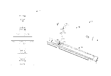
[0029] FIG. 7 shows an example electronic and magnetic relationship
between a
stylus and a dock of an example stylus charging system 100. For example,
terminal 110a
of stylus 102 may be a ferromagnetic terminal configured to be magnetically
attracted to
permanent magnets 114a and 114b via magnetic force 702a and 702b,
respectively. The
magnetic force between terminal 110a and permanent magnets 114a and 114b serve
to
urge the stylus into a docked position as stylus 102 nears dock 104. Due to
the positioning
of the permanent magnets on either side of a charging contact, upon being
pulled into
contact with the magnets, ferromagnetic terminal 110a will also contact
charging contact
112a to provide the electrical connection illustrated by dashed line 704a. As
the charging
contact may be spring-loaded and biased to extend above the permanent magnets,
the
ferromagnetic terminal 110a will contact the charging contact before
contacting the
permanent magnets. The magnetic force between ferromagnetic terminal 110a and
.. permanent magnets 114a and 114b is strong enough to overcome the bias of
the spring-
loaded charging contacts and cause the ferromagnetic terminal to depress the
charging
contacts to come into face-sharing contact with the permanent magnets. The
bias of the
spring-loaded charging contacts urges the contact toward the terminal of the
stylus during
docking, thereby ensuring secure uninterrupted electrical contact while the
stylus is
docked.
[0030] As described above with respect to FIG. 2, additional
attractive forces may
be provided using one or more additional permanent magnets on dock 104 and
other
ferromagnetic terminal on the stylus (e.g., terminal 110c of FIG. 5, battery
106, and/or
another ferromagnetic element of stylus 102). Such additional magnetic
attraction may be
utilized for further alignment and/or to strengthen the magnetic force between
the dock
and the stylus as a whole and further secure the stylus to the dock while in
the docked
position.
[0031] Continuing with FIG. 7, a second charging contact 112b may be
spaced
from the pelluanent magnets and charging contact 112a (which is disposed
between the
permanent magnets) by a distance that is equal to the distance between
terminals 110a and
110b. In this way, the magnetic force that brings terminal 110a into contact
with
permanent magnets 114a and 114b also aligns terminal 110b with charging
contact 112b.
Accordingly, an electrical connection between terminal 110b and charging
contact 112b
may be made, as represented by dashed line 704b.
9
CA 02949131 2016-11-14
WO 2015/200564 PCT/US2015/037559
[0032] FIG. 8 shows an example docked position of stylus 102 within
dock 104 of
a stylus charging system 100. As illustrated, stylus 102 is seated within a
depressed region
of dock 104 (described above in more detail with respect to FIG. 2). In this
way, terminals
110 of stylus 102 are in electrical contact with respective charging contacts
of dock 104 in
the manner described above with respect to FIG. 7.
[0033] A stylus charging system that incorporates ferromagnetic
charging
terminals on a stylus as described above enables system to provide the dual
functionality
of aligning/securing the stylus in a docked position and providing an
electrical connection
between the ferromagnetic charging terminals of the stylus and the charging
contacts of
the dock. Such ferromagnetic attraction may even enable the stylus to remain
seated in the
dock in a vertical orientation. Further, by providing permanent magnets on the
dock that
are near, yet electrically isolated from a charging contact of the dock
reduces wear and
tear on the permanent magnets and enables more appropriate materials to be
used for each
of the permanent magnets and the charging contacts.
[0034] In some embodiments, the methods and processes described herein may
be
tied to a computing system of one or more computing devices. In particular,
such methods
and processes may be implemented as a computer-application program or service,
an
application-programming interface (API), a library, and/or other computer-
program
product.
[0035] It will be understood that the configurations and/or approaches
described
herein are exemplary in nature, and that these specific embodiments or
examples are not to
be considered in a limiting sense, because numerous variations are possible.
The specific
routines or methods described herein may represent one or more of any number
of
processing strategies. As such, various acts illustrated and/or described may
be performed
in the sequence illustrated and/or described, in other sequences, in parallel,
or omitted.
Likewise, the order of the above-described processes may be changed.
[0036] The subject matter of the present disclosure includes all novel
and non-
obvious combinations and sub-combinations of the various processes, systems
and
configurations, and other features, functions, acts, and/or properties
disclosed herein, as
well as any and all equivalents thereof.