Note: Descriptions are shown in the official language in which they were submitted.
CA 02949458 2017-02-03
REPLACEABLE UNIT FOR AN IMAGE FORMING DEVICE HAVING MAGNETS
OF VARYING ANGULAR OFFSET FOR TONER LEVEL SENSING
BACKGROUND
[0001] 1. Field of the Disclosure
[0002] The present disclosure relates generally to image forming
devices and
more particularly to a replaceable unit for an image forming device having
magnets of
varying angular offset for toner level sensing.
[0003] 2. Description of the Related Art
[0004] During the electrophotographic printing process, an electrically
charged
rotating photoconductive drum is selectively exposed to a laser beam. The
areas of the
photoconductive drum exposed to the laser beam are discharged creating an
electrostatic
latent image of a page to be printed on the photoconductive drum. Toner
particles are
then electrostatically picked up by the latent image on the photoconductive
drum creating
a toned image on the drum. The toned image is transferred to the print media
(e.g.,
paper) either directly by the photoconductive drum or indirectly by an
intermediate
transfer member. The toner is then fused to the media using heat and pressure
to
complete the print.
[0005] The image forming device's toner supply is typically stored in
one or more
replaceable units installed in the image forming device. As these replaceable
units run
out of toner, the units must be replaced or refilled in order to continue
printing. As a
result, it is desired to measure the amount of toner remaining in these units
in order to
warn the user that one of the replaceable units is near an empty state or to
prevent
printing after one of the units is empty in order to prevent damage to the
image forming
device. Accordingly, a system for measuring the amount of toner remaining in a
replaceable unit of an image forming device is desired.
SUMMARY
[0005a] According to the present invention, there is provided a
replaceable unit for
an electrophotographic image forming device, comprising:
a housing having a reservoir for storing toner;
1
a rotatable shaft positioned within the reservoir and having an axis of
rotation;
a first magnet and a second magnet connected to the rotatable shaft and
rotatable around the axis of rotation in response to rotation of the
rotatable shaft, the first magnet and the second magnet passing near at
least a portion of an inner wall of the housing forming the reservoir
during rotation of the first and second magnets, wherein an amount of
angular offset between the first magnet and the second magnet varies
depending on an amount of said toner in the reservoir; and
a first linkage rotatable with the rotatable shaft and rotatable independent
of
the rotatable shaft between a forward rotational stop and a rearward
rotational stop, the second magnet mounted on the first linkage, the
second magnet is spaced angularly rearward relative to an operative
rotational direction of the rotatable shaft from the first magnet when the
first linkage is at the forward rotational stop.
[0005b] According to the present invention, there is also provided a
replaceable unit
for an electrophotographic image forming device, comprising:
a housing having a reservoir for storing toner;
a rotatable shaft positioned within the reservoir and having an axis of
rotation;
a first magnet rotatable with the rotatable shaft; and
a sensing linkage rotatable with the rotatable shaft and rotatable independent
of the rotatable shaft between a forward rotational stop and a rearward
rotational stop, the sensing linkage having a paddle member leading the
first magnet in an operative rotational direction of the rotatable shaft and
a second magnet trailing the first magnet in the operative rotational
direction of the rotatable shaft.
[0005c] According to the present invention, there is also provided a
replaceable unit
for an electrophotographic image forming device, comprising:
a housing having a reservoir for storing toner;
a rotatable shaft positioned within the reservoir and having an axis of
rotation;
a first linkage fixed to rotate with the rotatable shaft;
la
CA 2949458 2018-04-20
a first magnet on the first linkage detectable by a magnetic sensor when the
replaceable unit is installed in the image forming device;
a second linkage rotatable with the rotatable shaft and rotatable independent
of the rotatable shaft between a forward rotational stop and a rearward
rotational stop; and
a second magnet on the second linkage substantially axially aligned with the
first magnet and detectable by the magnetic sensor when the replaceable
unit is installed in the image forming device, the second magnet is spaced
angularly rearward relative to an operative rotational direction of the
rotatable shaft from the first magnet when the second linkage is at the
forward rotational stop.
[0005d]
According to the present invention, there is also provided a replaceable unit
for an electrophotographic image forming device, comprising:
a housing having a reservoir for storing toner;
a rotatable shaft positioned within the reservoir and having an axis of
rotation;
a first linkage rotatable with the rotatable shaft and having a first magnet;
and
a second linkage rotatable with the rotatable shaft and rotatable independent
of the rotatable shaft between a forward rotational stop and a rearward
rotational stop, the second linkage having a second magnet,
wherein the second linkage is biased by a biasing member in an operative
rotational direction of the rotatable shaft toward the forward rotational
stop and an amount of angular offset between the first magnet and the
second magnet varies depending on an amount of toner in the reservoir.
[0005e]
According to the present invention, there is also provided a replaceable unit
for an electrophotographic image forming device, comprising:
a housing having a reservoir for storing toner; a rotatable shaft positioned
within the reservoir and having an axis of rotation;
a first linkage rotatable with the rotatable shaft around the axis of
rotation,
the first linkage having a first magnet;
a second linkage rotatable around the axis of rotation in response to rotation
of the rotatable shaft, the second linkage having a paddle member leading
lb
CA 2949458 2018-04-20
the first magnet in an operative rotational direction of the rotatable shaft
and a second magnet trailing the first magnet in the operative rotational
direction of the rotatable shaft, the second linkage is rotatable
independent of the rotatable shaft between a forward rotational stop and
a rearward rotational stop such that an amount of angular offset between
the first magnet and the second magnet varies depending on a rotational
position of the second linkage relative to the forward rotational stop and
the rearward rotational stop.
[0005f]
According to the present invention, there is also provided a replaceable unit
for an electrophotographic image forming device, comprising:
a housing having a reservoir for storing toner; a rotatable shaft positioned
within the reservoir and having an axis of rotation;
a first linkage rotatable with the rotatable shaft, the first linkage having a
first magnet;
a second linkage rotatable in response to rotation of the rotatable shaft, the
second linkage having a paddle member leading the first magnet in an
operative rotational direction of the rotatable shaft and a second magnet
trailing the first magnet in the operative rotational direction of the
rotatable shaft, the second linkage is rotatable independent of the
rotatable shaft between a forward rotational stop and a rearward
rotational stop such that an amount of angular offset between the first
magnet and the second magnet varies depending on a rotational position
of the second linkage relative to the forward rotational stop and the
rearward rotational stop,
wherein the first magnet and the second magnet pass near a point on an inner
wall of the housing forming the reservoir once per revolution of the
rotatable shaft for detection by a magnetic sensor when the replaceable
unit is installed in the image forming device.
[0005g]
According to the present invention, there is also provided a replaceable unit
for an electrophotographic image forming device, comprising:
a housing having a reservoir for storing toner;
a rotatable shaft positioned within the reservoir and having an axis of
rotation;
1C
CA 2949458 2018-04-20
a first linkage fixed to rotate with the rotatable shaft around the axis of
rotation, the first linkage having a first magnet; a second linkage rotatable
around the axis of rotation in response to rotation of the rotatable shaft,
the second linkage having a paddle member leading the first magnet in
an operative rotational direction of the rotatable shaft and a second
magnet trailing the first magnet in the operative rotational direction of
the rotatable shaft, the second linkage is rotatable independent of the
rotatable shaft between a forward rotational stop and a rearward
rotational stop such that an amount of angular offset between the first
magnet and the second magnet varies depending on a rotational position
of the second linkage relative to the forward rotational stop and the
rearward rotational stop, the second linkage completes a revolution
around the axis of rotation once per revolution of the rotatable shaft.
[0005h] Preferred embodiments are described hereunder.
[0006] A
replaceable unit for an electrophotographic image forming device
according to one example embodiment includes a housing having a reservoir for
storing
toner. A rotatable shaft is positioned within the reservoir and has an axis of
rotation. A
first magnet and a second magnet are cormected to the shaft and rotatable
around the axis
of rotation in response to rotation of the shaft. The first magnet and the
second magnet
pass near at least a portion of an inner wall of the housing forming the
reservoir during
rotation of the first and ____________________________________________
id
CA 2949458 2018-04-20
CA 02949458 2016-11-16
WO 2015/187438 PCT/US2015/032783
second magnets. An amount of angular offset between the first magnet and the
second
magnet varies depending on an amount of toner in the reservoir. In some
embodiments, the
first magnet is substantially axially aligned with the second magnet with
respect to the axis of
rotation. In some embodiments, the first magnet is substantially radially
aligned with the
second magnet with respect to the axis of rotation. Some embodiments include a
first linkage
rotatable with the shaft and rotatable independent of the shaft between a
forward rotational
stop and a rearward rotational stop and the second magnet mounted on the first
linkage.
Additional embodiments include a second linkage fixed to rotate with the shaft
and the first
magnet mounted on the second linkage. In some embodiments, the first linkage
has a paddle
member leading the first magnet in an operative rotational direction of the
shaft and the
second magnet trails the first magnet in the operative rotational direction of
the shaft.
Embodiments include those wherein the first linkage is biased in an operative
rotational
direction of the shaft toward the forward rotational stop.
[00071 .A replaceable unit for an electrophotographi.c image forming
device according
.. to another example embodiment includes a housing having a reservoir for
storing toner. A
rotatable shaft is positioned within the reservoir and has an axis of
rotation. A. first magnet is
rotatable with the shaft. A sensing linkage is rotatable with the shaft and
rotatable
independent of the shaft between a forward rotational stop and a rearward
rotational stop.
The sensing linkage has a paddle member leading the first magnet in an
operative rotational
direction of the shaft and a second magnet trailing the first magnet in the
operative rotational
direction of the shaft.
[00081 A replaceable unit for an electrophotographic image forming
device according
to another example embodiment includes a housing having a reservoir for
storing toner. A
rotatable shaft is positioned within the reservoir and has an axis of
rotation. A first linkage is
fixed to rotate with the shaft. A first magnet on the first linkage is
detectable by a magnetic
sensor when the replaceable unit is installed in the image formi.ng device. A
second linkage
is rotatable with the shaft and rotatable independent of the shaft between a
forward rotational
stop and a rearward rotational stop. A second magnet on the second linkage is
substantially
axially aligned with the first magnet and detectable by the magnetic sensor
when the
replaceable unit is installed in the image forming device.
2
CA 02949458 2016-11-16
WO 2015/187438
PCT/US2015/032783
BRIEF DESCRIPTION OF THE DRAWINGS
[0009] The accompanying drawings incorporated in and forming a part of
the
specification, illustrate several aspects of the present disclosure, and
together with the
description serve to explain the principles of the present disclosure.
[0010] Figure 1 is a block diagram of an imaging system according to one
example
embodiment.
[0011] Figure 2 is a perspective view of a toner cartridge and an
imaging unit
according to one example embodiment.
[00121 Figures 3 and 4 are additional perspective views of the toner
cartridge shown
in Figure 2.
[0013] Figure 5 is an exploded view of the toner cartridge shown in
Figure 2 showing
a reservoir for holding toner therein.
100141 Figure 6 is a perspective view of a paddle assembly of the
toner cartridge
according to one example embodiment.
[0015] Figures 7.A-C are cross-sectional side views of the toner cartridge
illustrating
the operation of a sensing linkage at various toner levels according to one
example
embodiment.
[0016] Figure 8 is a graph of an angular separation between a
reference magnet and
sense magnets at the point where they pass a magnetic sensor versus an amount
of toner
remaining in the reservoir of the toner cartridge according to one example
embodiment.
[0017] Figure 9A is a perspective view of a sensing linkage according
to a second
example embodiment.
[0018] Figure 9B is a perspective view of a sensing linkage according
to a third
example embodiment.
[0019] Figure 9C is a perspective view of a sensing linkage according to a
fourth
example embodiment.
[0020] Figure 10 is a perspective view of a paddle assembly of the
toner cartridge
according to another example embodiment.
3
CA 02949458 2017-02-03
DETAILED DESCRIPTION
[0021] In the following description, reference is made to the
accompanying
drawings where like numerals represent like elements. The embodiments are
described in
sufficient detail to enable those skilled in the art to practice the present
disclosure. It is to
be understood that other embodiments may be utilized and that process,
electrical, and
mechanical changes, etc., may be made without departing from the scope of the
present
disclosure. Examples merely typify possible variations. Portions and features
of some
embodiments may be included in or substituted for those of others. The
following
description, therefore, is not to be taken in a limiting sense.
[0022] Referring now to the drawings and particularly to Figure 1, there is
shown
a block diagram depiction of an imaging system 20 according to one example
embodiment. Imaging system 20 includes an image forming device 22 and a
computer
24. Image forming device 22 communicates with computer 24 via a communications
link
26. As used herein, the term "communications link" generally refers to any
structure that
facilitates electronic communication between multiple components and may
operate
using wired or wireless technology and may include communications over the
Internet.
[0023] In the example embodiment shown in Figure 1, image forming
device 22
is a multifunction machine (sometimes referred to as an all-in-one (AIO)
device) that
includes a controller 28, a print engine 30, a laser scan unit (LSU) 31, an
imaging unit 32,
a toner cartridge 35, a user interface 36, a media feed system 38, a media
input tray 39
and a scanner system 40. Image forming device 22 may communicate with computer
24
via a standard communication protocol, such as for example, universal serial
bus (USB),
Ethernet or IEEE 802.xx. Image forming device 22 may be, for example, an
electrophotographic printer/copier including an integrated scanner system 40
or a
standalone electrophotographic printer.
[0024] Controller 28 includes a processor unit and associated memory
29. The
processor may include one or more integrated circuits in the form of a
microprocessor or
central processing unit and may be formed as one or more Application-specific
integrated
circuits (ASICs). Memory 29 may be any volatile or non-volatile memory of
combination thereof such as, for example, random access memory (RAM), read
only
memory (ROM), flash memory and/or non-volatile RAM (NVRAM). Alternatively,
memory 29 may be in the form of a separate electronic memory (e.g., RAM, ROM,
and/or NVRAM), a hard drive, a ________________________________________
4
CA 02949458 2016-11-16
WO 2015/187438
PCT/US2015/032783
CD or DVD drive, or any memory device convenient for use with controller 28.
Controller
28 may be, for example, a combined printer and scanner controller.
100251 in the example embodiment illustrated, controller 28
communicates with print
engine 30 via a communications link 50. Controller 28 communicates with
imaging unit 32
and processing circuitry 44 thereon via a communications link 51. Controller
28
communicates with toner cartridge 35 and processing circuitry 45 thereon via a
communications link 52. Controller 28 communicates with media feed system 38
via a
communications link 53. Controller 28 communicates with scanner system 40 via
a
communications link 54. User interface 36 is communicatively coupled to
controller 28 via a
communications link 55. Processing circuitry 44, 45 may provide authentication
functions,
safety and operational interlocks, operating parameters and usage information
related to
imaging unit 32 and toner cartridge 35, respectively. Controller 28 processes
print and scan
data and operates print engine 30 during printing and scanner system 40 during
scanning.
[00261 Computer 24, which is optional, may be, for example, a personal
computer,
.. including memory 60, such as RAM, ROM, and/or NVRAM, an input device 62,
such as a
keyboard and/or a mouse, and a display monitor 64. Computer 24 also includes a
processor,
input/output (I/O) interfaces, and may include at least one mass data storage
device, such as a
hard drive, a CD-ROM and/or a DVD unit (not shown). Computer 24 may also be a
device
capable of communicating with image forming device 22 other than a personal
computer
such as, for example, a tablet computer, a smartphone, or other electronic
device.
[00271 In the example embodiment illustrated, computer 24 includes in
its memory a
software program including program instructions that function as an imaging
driver 66, e.g.,
printer/scanner driver software, for image forming device 22. Imaging driver
66 is in
communication with controller 28 of image forming device 22 via communications
link 26.
Imaging driver 66 facilitates communication between image forming device 22
and computer
24. One aspect of imaging driver 66 may be, for example, to provide formatted
print data to
image forming device 22, and more particularly to print engine 30, to print an
image.
Another aspect of imaging driver 66 may be, for example, to facilitate
collection of scanned
data from scanner system 40.
[0028j In some circumstances, it may be desirable to operate image forming
device
22 in a standalone mode. In the standalone mode, image forming device 22 is
capable of
functioning without computer 24. Accordingly, all or a portion of imaging
driver 66, or a
5
CA 02949458 2016-11-16
WO 2015/187438
PCT/US2015/032783
similar driver, may be located in controller 28 of image forming device 22 so
as to
accommodate printing and/or scanning functionality when operating in the
standalone mode.
100291 Print engine 30 includes a laser scan unit (LSO 31, toner
cartridge 35,
imaging unit 32, and a fuser 37, all mounted within image forming device 22.
Imaging unit
.. 32 is removably mounted in image forming device 22 and includes a developer
unit 34 that
houses a toner sump and a toner delivery system. In one embodiment, the toner
delivery
system utilizes what is commonly referred to as a single component development
system. In
this embodiment, the toner delivery system includes a toner adder roll that
provides toner
from the toner sump to a developer roll. A doctor blade provides a metered
uniform layer of
.. toner on the surface of the developer roll. In another embodiment, the
toner delivery system
utilizes what is commonly referred to as a dual component development system.
In this
embodiment, toner in the toner sump of developer unit 34 is mixed with
magnetic carrier
beads. The magnetic carrier beads may be coated with a polymeric film to
provide
tiiboelectric properties to attract toner to the carrier beads as the toner
and the magnetic
.. carrier beads are mixed in the toner sump. In this embodiment, developer
unit 34 includes a
magnetic roll that attracts the magnetic carrier beads having toner thereon to
the magnetic roll
through the use of magnetic fields.
[00301 Imaging unit 32 also includes a cleaner unit 33 that houses a
photoconductive
drum. and a waste toner removal system.. Toner cartridge 35 is removably
mounted in
imaging forming device 22 in a mating relationship with developer unit 34 of
imaging unit
32. An outlet port on. toner cartridge 35 communicates with an entrance port
on developer
unit 34 allowing toner to be periodically transferred from toner cartridge 35
to resupply the
toner sump in developer unit 34.
[00311 The electrophotographic printing process is well known in the
art and,
.. therefore, is described briefly herein. During a printing operation, laser
scan unit 31 creates a
latent image on the photoconductive drum in cleaner unit 33. Toner is
transferred from the
toner sump in developer unit 34 to the latent image on the photoconductive
drum by the
developer roll (in the case of a single component development system) or by
the magnetic
roll (in the case of a dual component development system.) to create a toned
image. The
toned image is then transferred to a media sheet received by imaging unit 32
from media
input tray 39 for printing. Toner may be transferred directly to the media
sheet by the
photoconductive drum or by an intermediate transfer member that receives the
toner from the
photoconductive drum. Toner remnants are removed from the photoconductive drum
by the
6
CA 02949458 2016-11-16
WO 2015/187438 PCT/US2015/032783
waste toner removal system. The toner image is bonded to the media sheet in
fuser 37 and
then. sent to an output location or to one or more finishing options such as a
duplexer, a
stapler or a hole-punch.
100321 Referring now to Figure 2, a toner cartridge 100 and an imaging
unit 200 are
shown according to one example embodiment. Imaging unit 200 includes a
developer unit
202 and a cleaner unit 204 mounted on a common frame 206. As discussed above,
imaging
unit 200 and toner cartridge 100 are each removably installed in image forming
device 22.
Imaging unit 200 is first slidably inserted into image forming device 22.
Toner cartridge 100
is then inserted into image forming device 22 and onto frame 206 in a mating
relationship
with developer unit 202 of imaging unit 200 as indicated by the arrow shown in
Figure 2.
This arrangement allows toner cartridge 100 to be removed and reinserted
easily when
replacing an empty toner cartridge 100 without having to remove imaging unit
200. Imaging
unit 200 may also be readily removed as desired in order to maintain, repair
or replace the
components associated with developer unit 202, cleaner unit 204 or frame 206
or to clear a
media jam.
[00331 With reference to Figures 2-5, toner cartridge 100 includes a
housing 102
having an enclosed reservoir 104 (Figure 5) for storing toner. Housing 102 may
include a top
or lid 106 mounted on a base 108. Base 108 includes first and second side
walls 110, 112
connected to adjoining front and rear walls 114, 116 and a bottom 117. In one
embodiment,
top 106 is ultrasonically welded to base 108 thereby forming enclosed
reservoir 104. First
and second end caps 118, 120 may be mounted to side walls 110, 112,
respectively, and may
include guides 122 to assist the insertion of toner cartridge 100 into image
forming device 22
for mating with developer unit 202. First and second end caps 118, 120 may be
snap fitted
into place or attached by screws or other fasteners. Guides 122 travel in
corresponding
channels within image forming device 22. Legs 124 may also be provided on
bottom 117 of
base 106 or end caps 118, 120 to assist with the insertion of toner cartridge
100 into image
forming device 22. Legs 124 are received by frame 206 to facilitate the mating
of toner
cartridge 100 with developer unit 202. A handle 126 may be provided on top 106
or base 108
of toner cartridge 100 to assist with insertion and removal of toner cartridge
100 from
imaging unit 200 and image forming device 22. An outlet port 128 is positioned
on front
wall 114 of toner cartridge 100 for exiting toner from toner cartridge 100.
[00341 With reference to Figure 5, various drive gears are housed
within a space
formed between end cap 118 and side wall 110. A main interface gear 130
engages with a
7
CA 02949458 2016-11-16
WO 2015/187438 PCT/US2015/032783
drive system in image forming device 22 that provides torque to main interface
gear 130. A
paddle assembly 140 is rotatabl.y mounted within toner reservoir 104 with
first and second
ends of a drive shaft 132 of paddle assembly 140 extending through aligned
openings in side
walls 110, 112, respectively. A drive gear 134 is provided on the first end of
drive shaft 132
that engages with main interface gear 130 either directly or via one or more
intermediate
gears. Bushings may be provided on each end of drive shaft 132 where it passes
through side
walls 110, 112.
[00351 An auger 136 having first and second ends 136a, 136b and a
spiral screw
flight is positioned in a channel 138 extending along the width of front wall
114 between side
walls 110, 112. Channel 138 may be integrally molded as part of front wall 114
or formed as
a separate component that is attached to front wall 114. Channel 138 is
generally horizontal
in orientation along with toner cartridge 100 when toner cartridge 100 is
installed in image
forming device 22. First end 136a of auger 136 extends through side wall 110
and a drive
gear (not shown.) is provided on first end 136a that engages with main
interface gear 130
either directly or via one or more intermediate gears. Channel 138 may include
an open
portion 138a and an enclosed portion 138b. Open portion 138a is open to toner
reservoir .104
and extends from side wall 110 toward second end 136b of auger 136. Enclosed
portion
138b of channel 138 extends from side wall 112 and encloses an optional
shutter and second
end 136b of auger 136. In this embodiment, outlet port 128 is positioned at
the bottom of
enclosed portion 138b of channel 138 so that gravity will assist in exiting
toner through outlet
port 128. The shutter is movable between a closed position blocking toner from
exiting outlet
port 128 and an open position permitting toner to exit outlet port 128.
[0036) As paddle assembly 140 rotates, it delivers toner from toner
reservoir 104 into
open portion 138a of channel 138. As auger 136 rotates, it delivers toner
received in channel
138 into enclosed portion 138b of channel 138 where the toner passes out of
outlet port 128
into a corresponding entrance port 208 in developer unit 202 (Figure 2). In
one embodiment,
entrance port 208 of developer unit 202 is surrounded by a foam seal 210 that
traps residual
toner and prevents toner leakage at the interface between outlet port 128 and
entrance port
208.
(0037) The drive system in image forming device 22 includes a drive motor
and a
drive transmission from. the drive m.otor to a drive gear that mates with main
interface gear
130 when toner cartridge 100 is installed in image forming device 22. The
drive system in
image forming device 22 may include an encoded device, such as an encoder
wheel, (e.g.,
8
CA 02949458 2016-11-16
WO 2015/187438 PCT/US2015/032783
coupled to a shaft of the drive motor) and an associated code reader, such as
an infrared
sensor, to sense the motion of the encoded device. The code reader is in
communication with
controller 28 in order to permit controller 28 to track the amount of rotation
of main interface
gear 130, auger 136 and paddle assembly 140.
[0038) Although the example embodiment shown in Figures 2-5 includes a pair
of
replaceable units in the form of toner cartridge 100 and imaging unit 200, it
will be
appreciated that the replaceable unit(s) of the image forming device may
employ any suitable
configuration as desired. For example, in one embodiment, the main toner
supply for the
image forming device, the developer unit, and the cleaner unit are housed in
one replaceable
unit. In another embodiment, the main toner supply for the image forming
device and the
developer unit are provided in a first replaceable unit and the cleaner unit
is provided in a
second replaceable unit. Further, although the example image forming device 22
discussed
above includes one toner cartridge and corresponding imaging unit, in the case
of an image
forming device configured to print in color, separate replaceable units may be
used for each
toner color needed. For example, in one embodiment, the image forming device
includes
four toner cartridges and four corresponding imaging units, each toner
cartridge containing a
particular toner color (e.g., black, cyan, yellow and magenta) and each
imaging unit
corresponding with one of the toner cartridges to permit color printing.
[0039) Figure 6 shows paddle assembly 140 in greater detail according
to one
example embodiment. In operation, shaft 132 rotates in the direction shown by
arrow A in
Figure 6. Paddle assembly 140 includes a fixed paddle 141 that is fixed to
shaft 132 such that
fixed paddle 141 rotates with shaft 132. In one embodiment shaft 132 extends
from side wall
110 to side wall 112. In the embodiment illustrated, fixed paddle 141 includes
a plurality of
arms 142 extending radially from shaft 132. In the example embodiment
illustrated, fixed
paddle 141 includes two sets 142a, 142b of arms 142. In this embodiment, in
the position
illustrated in Figure 6, arms 142 of first set 142a extend from shaft 132
toward rear wall 116
and arms 142 of second set 142b extend from shaft 132 toward front wall 114.
Of course
these positions change as shaft 132 rotates. The arms 142 of each set 142a,
142b are radially
aligned and axially offset from each other. The arms 142 of first set 142a are
offset
circumferentially by approximately 180 degrees from the arms 142 of second set
142b. Other
embodiments include one set of arms 142 or more than two sets of arms 142
extending from
shaft 132. In other embodiments, arms 142 are not arranged in sets. Further,
arms 142 may
extend radially or non-radially from shaft 132 in any manner desired.
9
CA 02949458 2016-11-16
WO 2015/187438 PCT/US2015/032783
[00401 Fixed paddle 141 may include a cross member 144 connected to
each set 142a,
142b of arms 142. Cross members 144 may extend across all or a portion of the
arms 142 of
sets 142a, 142b. Cross members 144 help arms 142 stir and mix toner in
reservoir 104 as
shaft 132 rotates. A breaker bar 146 that is generally parallel to shaft 132
may be positioned
radially outward from each cross member 144 and connected to the distal ends
of arms 142.
Breaker bars 146 are positioned in close proximity to inner surfaces of
housing 102 without
making contact with the inner surfaces of housing 102 to help break apart
toner clumped near
the inner surfaces of housing 102. Scrapers 148 may extend in a cantilevered
manner from
cross members 144. Scrapers 148 are formed from a flexible material such as a
polyethylene
terephthalate (PET) material, e.g., MYLARO available from DuPont Teijin Films,
Chester,
Virginia, USA. Scrapers 148 form an interference fit with the inner surfaces
of top 106, front
wall 114, rear wall 116 and bottom 117 to wipe toner from the inner surfaces
of reservoir
104. Scrapers 148 also push toner into open portion 138a of channel 138 as
shaft 132 rotates.
Specifically, as cross member 144 rotates past open portion 138a of channel
138, from
bottom 117 to top 106, the interference fit between scraper 148 and the inner
surface of front
wall 114 causes scraper 148 to have an elastic response as the scraper 148
passes open
portion 138a of channel 138 thereby flicking or pushing toner toward open
portion 138a of
channel 138. Additional scrapers may be provided on arms 142 at the axial ends
of shaft 132
to wipe toner from the inner surfaces of side walls 110 and 112 as desired.
The arrangement
of fixed paddle 141 shown in Figure 6 is not intended to be limiting. Fixed
paddle 141 may
include any suitable combination of projections, agitators, paddles, scrapers
and linkages to
agitate and move the toner stored in reservoir 104 as desired.
[00411 In the example embodiment illustrated, a permanent magnet 150
is rotatable
with shaft 132 and detectable by a magnetic sensor as discussed in igeater
detail below. In
one embodiment, magnet 150 is connected to shaft 132 by fixed paddle 141. In
the example
embodiment illustrated, first set 142a of arms 142 includes a pair of axially
spaced arms 143
positioned at one axial end of shaft 132. Arms 143 initially extend radially
outward from
shaft 132 and then bend opposite the operative rotational direction of shaft
132 at the distal
ends of arms 143. A cross member 145 connects the distal ends of arms 143 and
extends
substantially parallel to shaft 132. In the example embodiment shown, magnet
150 is
positioned in a finger 152 that extends outward from cross member 145 toward
the inner
surfaces of housing 102. Finger 152 extends in close proximity to but does not
contact the
inner surfaces of housing 102 so that magnet 150 is positioned in close
proximity to the inner
CA 02949458 2016-11-16
WO 2015/187438 PCT/US2015/032783
surfaces of housing 102. In one embodiment, fixed paddle 141 is composed of a
non-
magnetic material and magnet 150 is held by a friction fit in a cavity in
finger 152. Magnet
150 may also be attached to finger 152 using an adhesive or fastener(s) so
long as magnet
150 will not dislodge from finger 152 during operation of toner cartridge 100.
Magnet 150
may be any suitable size and shape so as to be detectable by a magnetic
sensor. For example,
magnet 150 may be a cube, a rectangular, octagonal or other form of prism, a
sphere or
cylinder, a thin sheet or an amorphous object. In another embodiment, finger
152 is
composed of a magnetic material such that the body of finger 152 forms the
magnet 150.
Magnet .150 may be composed of any suitable material such as steel, iron,
nickel, etc. While
the example embodiment illustrated in Figure 6 shows magnet 150 mounted on
fmger 152 of
fixed paddle 141, magnet 150 may be positioned on any suitable linkage to
shaft 132 such as
a cross member, arm, projection, finger, agitator, paddle, etc. of fixed
paddle 141 or separate
from fixed paddle 141.
[00421 .A sensing linkage 160 is mounted to shaft 132. Sensing linkage
160 rotates
with shaft 132 but is movable to a certain degree independent of shaft 132.
Sensing linkage
160 is free to rotate forward and backward on shaft 1.32 relative to fixed
paddle 141 and to
magnet 150 between a forward rotational stop and a rearward rotational stop.
Sensing
linkage 160 includes a leading paddle member 162. In the embodiment
illustrated, leading
paddle member 162 is connected to shaft 132 by a pair of arms 164 positioned
between and
next to arms 143 of fixed paddle 141. Leading paddle member 162 includes a
paddle surface
166 that engages the toner in reservoir 104 as discussed in greater detail
below. In the
example embodiment illustrated, paddle surface 166 is substantially planar and
normal to the
direction of motion of sensing linkage 160 to allow paddle surface 166 to
strike toner in
reservoir 104.
[00431 Sensing linkage 160 also includes one or more permanent magnets 168.
Magnet(s) 168 are mounted on one or more magnet support(s) 170 of sensing
linkage 160
that are positioned in close proximity to but do not contact the inner
surfaces of housing 102.
In this manner, magnet(s) 168 are positioned in close proximity to the inner
surfaces of
housing 102 but the inner surfaces of housing 102 do not impede the motion of
sensing
linkage 160. In the example embodiment illustrated, magnet support 170 is
connected to
shaft 132 by a pair of arms 172 positioned between and next to arms 143 of
fixed paddle 141.
Arms 172 are connected to arms 164. In this embodiment, in the position
illustrated in Figure
6, arms 172 extend from shaft 132 toward top 106. Of course the position of
arms 172
11
CA 02949458 2016-11-16
WO 2015/187438 PCT/US2015/032783
changes as shaft 132 rotates. In this embodiment, magnet support 170 is
relatively thin in the
radial dimension and extends circumferentially relative to shaft 132 between
distal ends of
arms 172 along the rotational path of magnet(s) 168 to minimize the drag on
magnet support
170 as it passes through toner in reservoir 104. Along the operative
rotational direction A of
shaft 132, leading paddle member 162 is positioned ahead of magnet 150 which
is positioned
ahead of magnet(s) 168.
[00441 In the example embodiment illustrated, two magnets 168a, 168b
are mounted
on magnet support 170; however, one magnet 168 or more than two magnets 168
may be
used as desired as discussed below. Magnets 168a, 168b are substantially
radially and axially
.. aligned and spaced circumferentially from each other relative to shaft 132.
Magnet(s) 168
are also substantially radially and axially aligned and spaced
circumferentially from magnet
150 relative to shaft 132. In one embodiment, magnet support 170 is composed
of a non-
magnetic material and magnet(s) 168 are held by a friction fit in one or more
cavities in
magnetic support 170. Magnet(s) 168 may also be attached to magnet support 170
using an
adhesive or fastener(s) so long as magnet(s) 168 will not dislodge from magnet
support 170
during operation of toner cartridge 100. .As discussed above, magnet(s) 168
may be any
suitable size and shape and composed of any suitable material. Magnet support
170 may take
many different forms including an arm, projection, linkage, cross member, etc.
[0045) In some embodiments, sensing linkage 160 is biased in the
operative rotational
.. direction toward a forward rotational stop by one or more biasing members.
In the example
embodiment illustrated, sensing linkage 160 is biased by an extension spring
176 connected
at one end to an arm 172 of magnet support 170 and at the other end to arm 143
of fixed
paddle 141. However, any suitable biasing member may be used as desired. For
example, in
another embodiment, a torsion spring biases sensing linkage 160 in the
operative rotational
direction. In another embodiment, a compression spring is connected at one end
to an arm
164 of leading paddle member 162 and at the other end to arm. 143 of fixed
paddle 141. In
another embodiment, sensing linkage 160 is free to fall by gravity toward its
forward
rotational stop as sensing linkage 160 rotates past the uppermost point of its
rotational path.
In the example embodiment illustrated, the forward rotational stop includes a
stop 178 that
.. extends axially from the side of one or both of the arms 172 of magnet
support 170. Stop 178
is arched and includes a leading surface 180 that contacts arm 143 of fixed
paddle 141 to
limit the motion of sensing linkage 160 relative to magnet 150 in the
operative rotational
direction. In the example embodiment illustrated, the rearward rotational stop
includes a
12
CA 02949458 2016-11-16
WO 2015/187438
PCT/US2015/032783
trailing portion 182 of leading paddle member 162. Trailing portion 182 of
leading paddle
member 162 contacts a leading portion 184 of cross member 145 to limit the
motion of
sensing linkage 160 relative to magnet 150 in a direction opposite the
operative rotational
direction. It will be appreciated that the forward and rearward rotational
stops may take other
forms as desired.
[00461
Figures 7A-7C depict the operation of magnets 150 and 168 at various toner
levels. Figures 7A-7C depict a clock face in dashed lines along the rotational
path of shaft
132 and paddle assembly 140 in order to aid in the description of the
operation of magnets
150 and 168. A magnetic sensor 190 is positioned to detect the motion of
magnets 150 and
168 during rotation of shaft 132 in order to determine the amount of toner
remaining in
reservoir 104 as discussed in greater detail below. In one embodiment,
magnetic sensor 190
is mounted on housing 102 of toner cartridge 100. In this embodiment, magnetic
sensor 190
is in electronic communication with processing circuitry 45 of toner cartridge
100 so that
information from. magnetic sensor 190 can be sent to controller 28 of image
forming device
22. In another embodiment, magnetic sensor 190 is positioned on a portion of
image forming
device 22 adjacent to housing 102 when toner cartridge 100 is installed in
image forming
device 22. in this embodiment, magnetic sensor 190 is in electronic
communication with
controller 28. In the example embodiment illustrated, magnetic sensor 190 is
positioned
adjacent to or on top 106. In other embodiments, magnetic sensor 190 is
positioned adjacent
to or on bottom 117, front wall 114, rear wall 116 or side wall 110 or 112. In
those
embodiments where magnetic sensor 190 is positioned adjacent to or on top 106,
bottom 117,
front wall 114 or rear wall 116, magnets 150 and 168 are positioned adjacent
to the inner
surfaces of top 106, bottom 117, front wall 114 or rear wall 116 as shaft 132
rotates, such as
at the radial ends of fixed paddle 141 and sensing linkage 160. In those
embodiments where
magnetic sensor 190 is positioned adjacent to or on side wall 110 or 112,
magnets 150 and
168 are positioned adjacent to the inner surface of side wall 110 or 112, such
as at the axial
ends of fixed paddle 141 and sensing linkage 160. Magnetic sensor 190 may be
any suitable
device capable of detecting the presence or absence of a magnetic field. For
example,
magnetic sensor 190 may be a hall-effect sensor, which is a transducer that
varies its
electrical output in response to a magnetic field. In the example embodiment
illustrated,
magnetic sensor 190 is positioned outside of reservoir 104 at about the "12
o'clock" position
relative to paddle assembly 140.
13
CA 02949458 2016-11-16
WO 2015/187438 PCT/US2015/032783
(0047) In one embodiment, the poles of magnets 150, 168 are directed
toward the
position of magnetic sensor 190 in order to facilitate the detection of
magnets 150, 168 by
magnetic sensor 190. Magnetic sensor 190 may be configured to detect one of a
north pole
and a south pole or both. Where magnetic sensor 190 detects one of a north
pole and a south
pole, magnets 150, 168 may be positioned such that the detected pole is
directed toward
magnetic sensor 190.
[00481 The motion of sensing linkage 160 and magnet(s) 168 relative to
magnet 150
as shaft 132 rotates may be used to determine the amount of toner remaining in
reservoir 104.
As shaft 132 rotates, in the embodiment illustrated, fixed paddle 141 rotates
with shaft 132
causing magnet 150 to pass magnetic sensor 190 at the same point during each
revolution of
shaft 132. On the other hand, the motion of sensing linkage 160, which is free
to rotate
relative to shaft 132 between its forward and rearward rotational stops,
depends on the
amount of toner 105 present in reservoir 104. As a result, magnet(s) 168 pass
magnetic
sensor 190 at different points during the revolution of shaft 132 depending on
the toner level
.. in reservoir 104. Accordingly, variation in the angular separation or
offset between magnet
150, which serves as a reference point, and magnet(s) 168, which provide(s)
sense points, as
they pass magnetic sensor 190 may be used to determine the amount of toner
remaining in
reservoir 104. In an alternative embodiment, the linkage connecting magnet 150
to shaft 132,
such as fixed paddle 141, is movable to a certain degree independent of shaft
132; however, it
is preferred that magnet 150 passes magnetic sensor 190 in the same position
relative to shaft
132 during each revolution of shaft 132 so that the position(s) of magnet(s)
168 may be
consistently evaluated relative to the position of magnet 150.
[0049) When toner reservoir 104 is relatively full, toner 105 present
in reservoir 104
prevents sensing linkage 160 from advancing ahead of its rearward rotational
stop. Instead,
sensing linkage 160 is pushed through its rotational path by fixed paddle 141
when shaft 132
rotates. Accordingly, when toner reservoir 104 is relatively full, the amount
of rotation of
shaft 132 between magnet 150 passing magnetic sensor 190 and magnets 168a,
168b on
sensing linkage 160 passing magnetic sensor 190 is at its maximum. In other
words, because
sensing linkage 160 is at its rearward rotational stop, the angular separation
from magnet
168a to magnet 150 when magnet 168a reaches magnetic sensor 190 and from
magnet 168b
to magnet 150 when magnet 168b reaches magnetic sensor 190 are at their
maximum limits.
[00501 As the toner level in reservoir 104 decreases as shown in
Figure 7A, sensing
linkage 160 is positioned forward from its rearward rotational stop as leading
paddle member
14
CA 02949458 2016-11-16
WO 2015/187438
PCT/US2015/032783
162 rotates forward from the "12 o'clock" position. Leading paddle member 162
advances
ahead of the rearward rotational stop of sensing linkage 160 until paddle
surface 166 contacts
toner 105, which stops the advance of sensing linkage 160. In one embodiment
where paddle
assembly 140 includes scrapers 148, scrapers 148 are not present on cross
member 144
connected to set 142b of arms 142 along the axial portion of shaft 132 spanned
by leading
paddle member 162 so that toner 105 is not disturbed immediately before paddle
surface 166
contacts toner 105 after leading paddle member 162 rotates forward from the
"12 o'clock"
position. At higher toner levels, leading paddle member 162 is stopped by
toner 105 before
magnets 168a, 168b reach magnetic sensor 190 such that the amount of rotation
of shaft 132
between magnet 150 passing magnetic sensor 190 and magnets 168a, 168b passing
magnetic
sensor 190 remains at its maximum. Sensing linkage 160 then remains generally
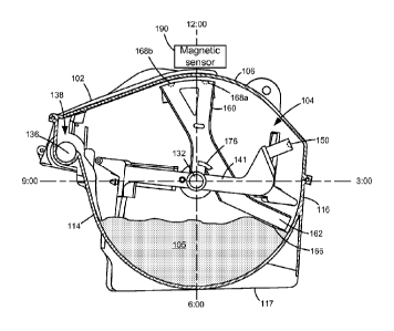
stationary
on top of (or slightly below) toner 105 until fixed paddle 141 catches up to
leading paddle
member 162 at the rearward rotational stop of sensing linkage 160 and fixed
paddle 141
resumes pushing sensing linkage 160.
100511 With reference to Figure 7B, as the toner level in reservoir 104
continues to
decrease, at the point where leading paddle member 162 encounters toner 105
magnet 168a is
detected by magnetic sensor 190. As a result, the amount of rotation of shaft
132 between
magnet 150 passing magnetic sensor 190 and magnet 168a passing magnetic sensor
190
decreases. Sensing linkage 160 then remains generally stationary on top of (or
slightly
below) toner 105 with magnet 168a in the sensing window of magnetic sensor 190
until fixed
paddle 141 catches up to leading paddle member 162 and resumes pushing sensing
linkage
160. As a result, leading paddle member 162 is stopped by toner 105 before
magnet 168b
reaches magnetic sensor 190 such that the amount of rotation of shaft 132
between magnet
150 passing magnetic sensor 190 and magnet 168b passing magnetic sensor 190
remains at
.. its maximum.
100521 With reference to Figure 7C, as the toner level in reservoir
104 decreases even
further, at the point where leading paddle member 162 encounters toner 105
magnet 168a has
passed magnetic sensor 190 and magnet 168b is detected by magnetic sensor 190.
As a
result, the amount of rotation of shaft 132 between magnet 150 passing
magnetic sensor 190
.. and magnets 168a and 168b passing magnetic sensor 190 are both decreased
relative to their
maximums. As a result, it will be appreciated that the motion of magnets 168a,
168b relative
to the motion of magnet 150 relates to the amount of toner 105 remaining in
reservoir 104.
CA 02949458 2016-11-16
WO 2015/187438 PCT/US2015/032783
10053] Figure 8 is a graph of the angular separation between magnet
150 and magnets
168a and 168b at the point where they pass magnetic sensor 190 versus the
amount of toner
105 remaining in reservoir 104 according to one example embodiment.
Specifically, line A is
the angular separation between magnet 150 and magnet 168a versus the amount of
toner 105
remaining in reservoir 104 and line B is the angular separation between magnet
150 and
magnet 168b versus the amount of toner 105 remaining in reservoir 104. As
shown in Figure
8, at higher toner levels, the amount of rotation of shaft 132 between magnet
150 passing
magnetic sensor 190 and magnets 168a, 168b passing magnetic sensor 190 remains
at its
maximum.. In this example, when about 450 grams of toner 105 remain in
reservoir 104,
leading paddle member 162 advances ahead of the rearward rotational stop of
sensing linkage
160 until paddle surface 166 contacts toner 105 at a point where magnet 168a
is in the
sensing window of magnetic sensor 190. As a result, the amount of rotation of
shaft 132
between magnet 150 passing magnetic sensor 190 and magnet 168a passing
magnetic sensor
190 decreases while the amount of rotation of shaft 132 between magnet 150
passing
magnetic sensor 190 and magnet 168b passing magnetic sensor 190 remains at its
maximum.
In this example, when about 300 grams of toner 105 remain in reservoir 104,
leading paddle
member 162 advances ahead of the rearward rotational stop of sensing linkage
160 until
paddle surface 166 contacts toner 105 at a point where magnet 168b is in the
sensing window
of magnetic sensor 190. As a result, the amount of rotation of shaft 132
between magnet 150
passing magnetic sensor 190 and magnets 168a and 168b passing magnetic sensor
190 are
both decreased relative to their maximums.
[1:10541 Information from magnetic sensor 190 may be used by controller
28 or a
processor in communication with controller 28, such as a processor of
processing circuitry
45, to aid in determining the amount of toner 105 remaining in reservoir 104.
In one
embodiment, the initial amount of toner 105 in reservoir 104 is recorded in
memory
associated with processing circuitry 45 upon filling the toner cartridge 100.
Accordingly,
upon installing toner cartridge 100 in image forming device 22, the processor
determining the
amount of toner 105 remaining in reservoir 104 is able to determine the
initial toner level in
reservoir 104. Alternatively, each toner cartridge 100 for a particular type
of image forming
device 22 may be filled with the same amount of toner so that the initial
toner level in
reservoir 104 used by the processor may be a fixed value for all toner
cartridges 100. The
processor then estimates the amount of toner remaining in reservoir 104 as
toner is fed from
toner cartridge to imaging unit 200 based on one or more operating conditions
of image
16
CA 02949458 2016-11-16
WO 2015/187438 PCT/US2015/032783
forming device 22 and/or toner cartridge 100. In one embodiment, the amount of
toner 105
remaining in reservoir 104 is approximated based on an empirically derived
feed rate of toner
105 from toner reservoir 104 when shaft 132 and auger 136 are rotated to
deliver toner from
toner cartridge 100 to imaging unit 200. In this embodiment, the estimate of
the amount of
toner 105 remaining is decreased based on the amount of rotation of the drive
motor of image
forming device 22 that provides rotational force to main interface gear 130 as
determined by
controller 28. In another embodiment, the estimate of the amount of toner 105
remaining is
decreased based on the number of printable elements (pels) printed using the
color of toner
contained in toner cartridge 100 while toner cartridge 100 is installed in
image forming
.. device 22. In another embodiment, the estimate of the amount of toner 105
remaining is
decreased based on the number of pages printed.
[00551 The amount of toner 105 remaining in reservoir 104 where the
amount of
rotation of shaft 132 that occurs between magnet 150 passing magnetic sensor
190 and each
of the magnets 168 passing magnetic sensor 190 decreases may be determined
empirically for
a particular toner cartridge design. As a result, each time the amount of
rotation of shaft 132
between the detection of magnet 150 and the detection of one of the magnets
168 decreases
from its maximum value, the processor may adjust the estimate of the amount of
toner
remaining in reservoir 104 based on the empirically determined amount of toner
associated
with the decrease in the amount of rotation of shaft 132 between magnet 150
passing
magnetic sensor 190 and the respective magnet 168 passing magnetic sensor 190.
[00561 For example, the toner level in reservoir 104 can be
approximated by starting
with the initial amount of toner 105 supplied in reservoir 104 and reducing
the estimate of the
amount of toner 105 remaining in reservoir 104 as toner 105 from reservoir 104
is consumed.
As discussed above, the estimate of the toner remaining may be decreased based
on one or
more conditions such as the number of rotations of the drive motor, main
interface gear 130
or shaft 132, the number of pets printed, the number of pages printed, etc.
The estimated
amount of toner remaining may be recalculated when the amount of rotation of
shaft 132 as
determined by controller 28 between magnet 150 passing magnetic sensor 190 and
magnet
168a of sensing linkage 160 passing magnetic sensor 190 decreases from its
maximum value.
In one embodiment, this includes replacing the estimate of the amount of toner
remaining
with the empirical value associated with the decrease in the amount of
rotation of shaft 132
between magnet 150 passing magnetic sensor 190 and magnet 168a passing
magnetic sensor
190. In another embodiment, the recalculation gives weight to both the present
estimate of
17
CA 02949458 2016-11-16
WO 2015/187438 PCT/US2015/032783
the amount of toner remaining and the empirical value associated with the
decrease in the
amount of rotation of shaft 132 between magnet 150 passing magnetic sensor 190
and magnet
168a passing magnetic sensor 190. The revised estimate of the amount of toner
105
remaining in reservoir 104 is then decreased as toner 105 from reservoir 104
is consumed
using one or more conditions as discussed above. The estimated amount of toner
remaining
may be recalculated again when the amount of rotation of shaft 132 as
determined by
controller 28 between magnet 150 passing magnetic sensor 190 and magnet 168b
of sensing
linkage 160 passing magnetic sensor 190 decreases from its maximum value. As
discussed
above, this may include replacing the estimate of the amount of toner
remaining or
recalculating the estimate giving weight to both the present estimate of the
amount of toner
remaining and the empirical value associated with the decrease in the amount
of rotation of
shaft 132 between magnet 150 passing magnetic sensor 190 and magnet 168b
passing
magnetic sensor 190. This process may be repeated until reservoir 104 is out
of toner 105. In
one embodiment, the present estimate of the amount of toner 105 remaining in
reservoir 104
is stored in memory associated with processing circuitry 45 of toner cartridge
100 so that the
estimate travels with toner cartridge 100 in case toner cartridge 100 is
removed from one
image forming device 22 and installed in another image forming device 22.
[00571 in this manner, the detection of the motion of magnets 168
relative to the
motion of magnet 150 may serve as a correction for an estimate of the toner
level in reservoir
.. 104 based on other conditions such as an empirically derived feed rate of
toner or the number
of pels or pages printed as discussed above to account for variability and to
correct potential
error in such an estimate. For example, an estimate of the toner level based
on conditions
such as an empirically derived feed rate of toner or the number of pels or
pages printed may
drift from the actual amount of toner 105 remaining in reservoir 104 over the
life of toner
cartridge 100, i.e., a difference between an estimate of the toner level and
the actual toner
level may tend to increase over the life of toner cartridge 100. Recalculating
the estimate of
the amount of toner 105 remaining based on the motion of magnet(s) 168
relative to the
motion of magnet 150 helps correct this drift to provide a more accurate
estimate of the
amount of toner 105 remaining in reservoir 104.
[00581 It will be appreciated that sensing linkage 160 may include any
suitable
number of magnets 168 desired depending on how many recalculations of the
estimate of the
amount of toner remaining are desired. For example, sensing linkage 160 may
include more
than two magnets 168 spaced circumferentially from each other where
recalculation of the
18
CA 02949458 2016-11-16
WO 2015/187438
PCT/US2015/032783
estimated toner level is desired more frequently. Alternatively, sensing
linkage 160 may
include a single magnet 168 where recalculation of the estimated toner level
is desired only
once, such as near the point where reservoir 104 is nearly empty. The
positions of magnets
168 relative to leading paddle member 162 may be selected in order to sense
particular toner
levels desired (e.g., 300 grams of toner remaining, 100 grams of toner
remaining, etc.).
Further, where shaft 132 rotates at a constant speed during operation of toner
cartridge 100,
time differences between the detection of magnet 150 and magnet(s) 168 by
magnetic sensor
190 may be used instead of the amount of rotation of shaft 132. In this
embodiment, time
differences greater than a predetermined threshold between the detection of
magnet 150 and
one or more of magnet(s) 168 may be ignored by the processor to account for
shaft 132
stopping between print jobs.
[0059.1 Sensing linkage 160 is not limited to the shape and
architecture shown in
Figure 6 and may take many shapes and sizes as desired. For example, Figure 9A
illustrates
a sensing linkage 1160 that includes a magnet support 1170 that extends
radially in the form
of an arm 1172. Magnet support 1170 is relatively thin in the axial direction
and includes
magnets 1168 that are aligned radially and axially and spaced
circumferentially from each
other. In this embodiment, magnets 1168 are positioned at an axial end of
sensing linkage
1160 in position to be detected by a magnetic sensor adjacent to or on side
wall 110 or 112.
Figure 9B illu,strates a sensing linkage 2160 that, like sensing linkage 160
discussed above
with respect to Figure 6, includes a pair of arms 2172 that connect a magnet
support 2170 to
shaft 132. Sensing linkage 2160 differs from sensing linkage 160 in that
magnet support
2170 and arms 2172 extend further in the circumferential dimension to
accommodate
additional magnets 2168. Figure 9C illustrates a sensing linkage 3160 that
includes a series
of circumferentially spaced and axially aligned radial arms 3172 that each
serve as a magnet
support 3170. In this embodiment, each magnet support 3170 positions a
respective magnet
3168 for detection by a magnetic sensor positioned adjacent to or on side wall
110 or 112.
10060] The leading paddle member 162 having paddle surface 166 that
engages the
toner in reservoir 104 may also take many shapes and sizes as desired. For
example, in one
embodiment, paddle surface 166 is angled with respect to the direction of
motion of the
sensing linkage 160. For example, paddle surface 166 may be V-shaped and have
a front
face that forms a concave portion of the V-shaped profile. In another
embodiment, paddle
surface 166 includes a comb portion with a series of teeth that are spaced
axially from each
19
CA 02949458 2016-11-16
WO 2015/187438 PCT/US2015/032783
other to decrease the friction between the sensing linkage and the toner. The
surface area of
paddle surface 166 may also vary as desired.
10061.1 Accordingly, an amount of toner remaining in a reservoir may be
determined
by sensing the relative motion between a sensing linkage and a fixed linkage
within the
reservoir. Because the motion of the sensing linkage and the fixed linkage are
detectable by a
sensor outside of reservoir 104, the sensing linkage and the fixed linkage may
be provided
without an electrical or mechanical connection to the outside of housing 102
(other than. shaft
132). This avoids the need to seal an additional connection into reservoir
104, which could
be susceptible to leakage. Positioning magnetic sensor 190 outside of
reservoir 104 reduces
the risk of toner contamination, which could damage the sensor. Magnetic
sensor 190 may
also be used to detect the installation of toner cartridge 100 in the image
forming device and
to confirm that shaft 132 is rotating properly thereby eliminating the need
for additional
sensors to perform these functions.
[00621 While the example embodiments illustrated in Figure 7A-7C show
magnetic
sensor 190 positioned at about "12 o'clock" with respect to paddle assembly
140, magnetic
sensor 190 may be positioned elsewhere in the rotational path of paddle
assembly 140 as
desired. For example, magnetic sensor 190 may be positioned at about "6
o'clock" with
respect to paddle assembly 140 by changing the positions of magnet 150 and
magnet(s) 168
relative to leading paddle member 162 by 180 degrees.
100631 Although the example embodiments discussed above utilize a sensing
linkage
and a fixed linkage in the reservoir of the toner cartridge, it will be
appreciated that a sensing
linkage and a fixed linkage each having a magnet may be used to determine the
toner level in
any reservoir or sump storing toner in image forming device 22 such as, for
example, a
reservoir of the imaging unit or a storage area for waste toner. Further,
although the example
embodiments discussed above discuss a system for determining a toner level, it
will be
appreciated that this system and the methods discussed herein may be used to
determine the
level of a particulate material other than toner such as, for example, grain,
seed, flour, sugar,
salt, etc.
[0064) While the examples discuss sensing magnets using a magnetic
sensor, in
another embodiment, an inductive sensor, such as an eddy current sensor, or a
capacitive
sensor is used instead of a magnetic sensor. In this embodiment, the fixed
linkage and the
sensing linkage include electrically conductive elements detectable by the
inductive or
CA 02949458 2017-02-03
capacitive sensor. As discussed above with respect to magnets 150 and 168, the
metallic
elements may be attached to the fixed linkage and the sensing linkage by a
friction fit,
adhesive, fastener(s), etc. or a portion of the fixed linkage and the sensing
linkage may be
composed of a metallic material.
[0065] Figure 10 shows another example embodiment of a paddle assembly
4140.
In this embodiment, the toner cartridge includes a paddle 4141 that is fixed
to a shaft
4132 such that paddle 4141 rotates with shaft 4132. Paddle 4141 includes a
plurality of
permanent magnets 4168 mounted on one or more magnet support(s) 4170. Magnets
4168 are positioned in close proximity to but do not contact the inner
surfaces of the
housing of the toner cartridge as discussed above. In the example embodiment
illustrated, magnet support 4170 is connected to shaft 4132 by a pair of arms
4172. In the
example embodiment illustrated, two magnets 4168a, 4168b are mounted on magnet
support 4170; however, more than two magnets 4168 may be used as desired.
Magnets
4168a, 4168b are substantially radially and axially aligned and spaced
circumferentially
from each other relative to shaft 4132. Magnets 4168 may be oriented, shaped
and
mounted to shaft 4132 in various ways as discussed above. In this embodiment,
magnetic
sensor 190 detects magnets 4168 as shaft rotates 4132. In this manner,
magnetic sensor
190 may be used to detect the presence of the toner cartridge in the image
forming device
and to confirm that shaft 4132 is rotating properly thereby eliminating the
need for
additional sensors to perform these functions. Magnetic sensor 190 may also be
used to
determine the speed of rotation of shaft 4132 by measuring the time difference
between
the detection of magnet 4168a and the detection of magnet 4168b as shaft 4132
rotates.
Magnetic sensor 190 may also be used to determine the amount of rotation of
shaft 4132
by counting the passes of magnets 4168.
[0066] The foregoing description illustrates various aspects of the
present
disclosure. It is not intended to be exhaustive. Rather, it is chosen to
illustrate the
principles of the present disclosure and its practical application to enable
one of ordinary
skill in the art to utilize the present disclosure, including its various
modifications that
naturally follow. All modifications and variations are contemplated within the
scope of
the present disclosure. Relatively apparent modifications include combining
one or more
features of various embodiments with features of other embodiments.
21