Note: Descriptions are shown in the official language in which they were submitted.
CA 02950095 2016-11-23
WO 2016/007131
PCT/US2014/045667
- 1 -
ACCUMULATOR COUNTERBALANCED THREE-CHAMBER CYLINDER
FOR ARTIFICIAL LIFT OPERATIONS
TECHNICAL FIELD
This disclosure relates generally to equipment utilized
and operations performed in conjunction with a subterranean
well and, in one example described below, more particularly
provides an accumulator counterbalanced three-chamber
cylinder for artificial lift operations.
BACKGROUND
Artificial lift systems are used to lift fluids from
wells in situations in which fluid reservoir pressure is
insufficient to flow the fluids to surface. It is important
that artificial lift systems operate efficiently and are
economical to construct, so that they are cost-effective in
use. Therefore, it will be appreciated that improvements are
continually needed in the art of constructing and operating
artificial lift systems for wells.
CA 02950095 2016-11-23
WO 2016/007131 PCT/US2014/045667
- 2 -
BRIEF DESCRIPTION OF THE DRAWINGS
FIG. 1 is a representative partially cross-sectional
view of an artificial lift system and associated method
which can embody principles of this disclosure.
FIG. 2 is a representative hydraulic schematic for a
lifting stage of operation.
FIG. 3 is a representative hydraulic schematic for a
retracting stage of operation.
FIG. 4 is a representative hydraulic schematic for a
cooling and/or make-up stage of operation.
FIG. 5 is a representative hydraulic schematic for a
remedial stage of operation.
DETAILED DESCRIPTION
Representatively illustrated in FIG. 1 is a system 10
for use with a well, and an associated method, which can
embody principles of this disclosure. However, it should be
clearly understood that the system 10 and method are merely
one example of an application of the principles of this
disclosure in practice, and a wide variety of other examples
are possible. Therefore, the scope of this disclosure is not
limited at all to the details of the system 10 and method
described herein and/or depicted in the drawings.
In the FIG. 1 example, an artificial lift system 12 is
used to pump fluid (such as hydrocarbons, water, etc.) from
a wellbore 14. For this purpose, the artificial lift system
12 includes a downhole pump 16 that is actuated by
reciprocation of a rod 18 (such as, a sucker rod).
In this example, the rod 18 is reciprocated by means of
a cylinder 20, sheave 22 and cable 24 at or near the earth's
CA 02950095 2016-11-23
WO 2016/007131 PCT/US2014/045667
- 3 -
surface. The cylinder 20 is used to displace the sheave 22
repeatedly up and down, thereby causing an end of the cable
24 attached to a polished rod 26 to reciprocate upward and
downward.
The polished rod 26 is received in a stuffing box 28 on
a wellhead 30. The polished rod 26 is connected to the rod
18, so that the rod 18 is reciprocated, thereby causing the
pump 16 to produce fluids upward to the wellhead 30.
A pressure supply 32 is used to actuate the cylinder
20, in order to cause the sheave 22 to displace upward and
downward. A control system 34 is used to control operation
of the cylinder 20 and pressure supply 32.
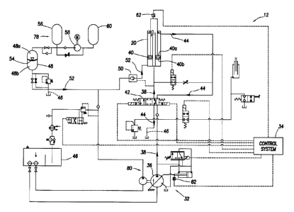
Referring additionally now to FIG. 2, a schematic
diagram of the artificial lift system 12 is representatively
illustrated. Only the cylinder 20, pressure supply 32 and
control system 34 are depicted in FIG. 2, so that the manner
in which operation of the cylinder is controlled can be more
clearly seen.
The pressure supply 32 includes a hydraulic pump 36 for
delivering pressurized fluid 38 to an upper side 40a of an
annular piston 40 in the cylinder 20. The pump 36 is a
variable displacement pump with electronic proportional
control in this example, but the scope of this disclosure is
not limited to use of any particular type of pump.
The pump 36 and associated equipment can be considered
a hydraulic pressure source 80 for delivering pressurized
fluid 38 to the cylinder 20. However, other types of
hydraulic pressure sources may be used in keeping with the
principles of this disclosure.
The fluid 38 is directed alternately to two separate
areas on the piston 40, depending on a position of a control
CA 02950095 2016-11-23
WO 2016/007131
PCT/US2014/045667
- 4 -
valve 42 connected between the pump 36 and the cylinder 20.
In the configuration of FIG. 1, the fluid 38 is directed to
a smaller, inner annular area of the upper piston side 40a.
The control valve 42 also directs a reduced pressure
fluid 44 from the cylinder 20 to a fluid reservoir 46, from
which the pump 36 draws. The reduced pressure fluid 44 is
displaced from the cylinder 20 due to upward displacement of
the piston 40. The fluid 44 is exposed to a larger, outer
annular area of the upper piston side 40a.
The piston 40 displaces upward in the FIG. 2
configuration due to fluid pressure applied from an
accumulator 48 to the lower side 40b of the piston 40. The
pressurized fluid 38 delivered by the pump 36 acts on a
pilot-controlled check valve 50, thereby opening the valve
and allowing pressurized fluid 52 to flow through the valve
and into the cylinder 20, where the fluid acts on the lower
side 40b of the piston 40.
Sufficient pressure is exerted by the fluid 52 on the
lower side 40b to overcome the pressures exerted by the
fluids 38, 44 on the upper side 40a of the piston, in
addition to force required to lift the rods 18, 26, so that
the piston 40 is displaced upward, thereby displacing the
sheave 22 (see FIG. 1) upward. It will be appreciated that
the accumulator 48 should be charged with pressure
accordingly.
In the FIG. 2 example, the accumulator 48 is a bladder-
type accumulator, having a flexible bladder 54 therein for
separating an upper gas-charged volume 48a of the
accumulator from a lower fluid filled volume 48b. Only one
accumulator 48 is depicted in FIG. 2, but multiple
accumulators may be used if desired. In addition,
accumulators other than bladder-type accumulators (such as,
CA 02950095 2016-11-23
,
,
WO 2016/007131 PCT/US2014/045667
- 5 -
piston-type accumulators, etc.) may be used if desired.
Thus, the scope of this disclosure is not limited to use of
any particular type or number of accumulator.
The accumulator volume 48a is pressurized by a
pressurized gas container 56 connected thereto. The gas
container 56 could be, for example, a pressurized nitrogen
bottle (or another pressurized inert gas container).
Multiple gas containers 56 may be used if desired to provide
sufficient pressurized gas volume. Thus, the scope of this
disclosure is not limited to use of any particular type or
number of gas container.
In the event that pressure in the accumulator 48 and
gas container 56 is less than a desired level (such as, due
to leakage, a requirement for more force output from the
cylinder 20, etc.), a gas compressor 58 can be used to
increase the pressure. The gas compressor 58 in the FIG. 2
example is supplied with gas from another gas container 60.
Thus, one or more gas container(s) 56 are on a discharge
side of the gas compressor 58, and one or more gas
container(s) 60 are on a supply side of the gas compressor.
The gas container 56, compressor 58 and gas container
60 can be considered as a gas pressure source 78 for
supplying gas pressure to the accumulator 48. However, other
types of gas pressure sources may be used, in keeping with
the principles of this disclosure.
As depicted in FIG. 2, the cylinder 20 is extended by
displacing the piston 40 upward. The piston 40 is displaced
upward by operating the control valve 42 to direct
pressurized fluid 38 from the pump 36 to the inner, smaller
area of the upper side 40a of the piston 40. This
pressurized fluid 38 causes the pilot-operated check valve
50 to open, thereby allowing pressurized fluid 52 to flow
CA 02950095 2016-11-23
,
,
WO 2016/007131 PCT/US2014/045667
-
- 6 -
from the accumulator 48 to the lower side 40b of the piston
40.
The pressure on the lower side 40b of the piston 40 is
sufficiently great to displace the piston upward. As the
piston 40 displaces upward, the fluid 44 is discharged from
the cylinder 20 and flows via the control valve 42 to the
reservoir 46.
The control system 34 controls operation of the control
valve 42. For example, the control system 34 will operate
the control valve 42 to its FIG. 2 configuration when it is
desired to upwardly displace the piston 40.
The control system 34 receives input from a variety of
sensors 62 (such as, pressure sensors, position sensors,
limit switches, proximity sensors, level sensors, etc., not
all of which are shown in the drawings) in the system 12, so
that the control system can determine when and how to
operate the control valve 42 and other equipment in the
system. For example, the control system 34 can receive an
indication from a sensor 62 on the cylinder 20 that the
piston 40 has reached a bottom of its stroke, and in
response the control system can operate the control valve 42
to its FIG. 2 configuration to thereby cause the piston 40
to displace upward.
Referring additionally now to FIG. 3, the system 12 is
representatively illustrated in a configuration in which the
piston 40 is being displaced downward. In order to
downwardly displace the piston 40, the control system 34
operates the control valve 42 so that pressurized fluid 38
from the pump 36 is directed to the larger, outer area on
the upper side 40a of the piston 40. Reduced pressure fluid
44 is directed from the smaller, inner area of the upper
CA 02950095 2016-11-23
WO 2016/007131 PCT/US2014/045667
- 7 -
side 40a of the piston 40 to the reservoir 46 by the control
valve 42.
Fluid 52 is flowed back to the accumulator 48 via the
check valve 50. The pressurized fluid 38 acting on the
larger, outer area of the upper side 40a of the piston 40,
combined with a weight of the rods 18, 26, etc., is great
enough to overcome the pressurized fluid 52 acting on the
lower side 40b of the piston 40, so that the piston 40
displaces downwardly.
The control system 34 will operate the control valve 42
to its FIG. 3 configuration when it is desired to downwardly
displace the piston 40. For example, the control system 34
can receive an indication from a sensor 62 on the cylinder
that the piston 40 has reached a top of its stroke, and
15 in response the control system can operate the control valve
42 to its FIG. 3 configuration to thereby cause the piston
40 to displace downward.
Referring additionally now to FIG. 4, the system 12 is
representatively illustrated in a cooling and/or make-up
20 configuration. In this configuration, additional fluid 64 is
added to the accumulator volume 48b (e.g., the fluid volume
in the accumulator and exposed to the lower side 40b of the
piston 40), if needed to, for example, compensate for any
leakage, etc.
The FIG. 4 configuration is substantially similar to
the FIG. 2 configuration, but an additional auxiliary pump
66 is used to pump fluid 64 from the reservoir 46 and via a
check valve 68 into the accumulator volume 48b (and the rest
of the volume between the accumulator 48 and the lower side
40b of the piston 40). The pump 66 is a gear pump in the
FIG. 4 example, but other types of pumps may be used, if
desired.
CA 02950095 2016-11-23
,
,
WO 2016/007131
PCT/US2014/045667
- 8 -
If it is desired to reduce a temperature of the
reservoir 46 (and fluids being pumped therefrom), a solenoid
vented relief valve 70 can be operated by the control system
34 to circulate the fluid from the pump 66 back to the
reservoir continuously, until the temperature has decreased
sufficiently. A heat exchanger 72 removes heat from the
fluid as it circulates.
Referring additionally now to FIG. 5, a configuration
of the system 12 is representatively illustrated, in which
the piston 40 can be displaced without use of fluid
pressure. Such a configuration could be useful, for example,
if the pump 36 has failed or is otherwise not operated, and
it is desired to lower the piston 40, in order to perform
maintenance, upgrade or repair operations on the system 12.
The control system 34 operates the control valve 42 to
a position in which the two areas (the larger, outer area
and the smaller, inner area) on the upper side 40a of the
piston 40 are prevented from communicating with the pump 36
and the reservoir 46. The control system 34 also operates
another valve 74 to thereby place these areas on the upper
side 40a of the piston 40 in communication with each other.
Another valve 76 is opened (for example, manually, or
by the control system 34), thereby venting pressure from the
accumulator 48 to the reservoir 46. The piston 40 will then
displace downward, for example, due to the weight of the
rods 18, 26, etc., applied to the sheave 22 above the
cylinder 20.
Another difference in the FIG. 5 example is that
multiple accumulators 48 and multiple gas containers 56 are
provided. Multiple gas containers 60 on the supply side of
the gas compressor 58 may also be provided, if desired. The
multiple accumulators 48 and gas containers 56 allow for use
CA 02950095 2016-11-23
WO 2016/007131
PCT/1JS2014/045667
- 9 -
of readily available standard-sized accumulators and
pressurized bottles, thereby eliminating a need for
customized accumulators and/or gas containers to be made.
However, customized accumulators and/or gas containers may
be used in keeping with the scope of this disclosure.
It may now be fully appreciated that the above
disclosure provides significant advancements to the art of
constructing and operating artificial lift systems for
wells. The system 12 described above is efficient,
effective, responsive, and convenient and economical to
construct and operate.
An artificial lift system 12 for use with a
subterranean well is provided to the art by the above
disclosure. In one example, the system 12 comprises a
cylinder 20 having a piston 40 reciprocably disposed
therein, the piston 40 having first and second opposing
sides 40a,b, the first side 40a having first and second
areas, each of the first and second areas being selectively
communicable with a hydraulic pressure source 80 and a
hydraulic reservoir 46, and the second side 40b being
selectively communicable with at least one accumulator 48;
and a gas pressure source 78 connected to the accumulator
48, the gas pressure source including a gas compressor 58
connected between at least one first gas container 60 and
the accumulator 48.
The gas pressure source can also include at least one
second gas container 56 connected to a discharge side of the
gas compressor 58. The second gas container 56 is connected
to the accumulator 48. The "at least one" second gas
container 56 can comprise multiple second gas containers.
The accumulator 48 may include a bladder 54. The
bladder 54 may be exposed on one side to the gas pressure
CA 02950095 2016-11-23
WO 2016/007131 PCT/US2014/045667
- 10 -
source 78, and on an opposite side the bladder may be
selectively communicable with the second side 40b of the
piston 40.
The "at least one" accumulator 48 can comprise multiple
accumulators.
A method of controlling an artificial lift system 12 is
also provided to the art by the above disclosure. In one
example, the method comprises connecting a cylinder 20 to a
hydraulic pressure source 80 and to at least one accumulator
48, the accumulator 48 being connected to a gas pressure
source 78, and operating a gas compressor 58 of the gas
pressure source, thereby increasing hydraulic pressure
applied to the cylinder 20 from the accumulator 48.
The method may include connecting at least one gas
container 56 to a discharge side of the gas compressor 58.
The method may include connecting the gas container 56 to
the accumulator 48.
The accumulator 48 may include a bladder 54, and the
bladder may be exposed on one side to the gas pressure
source 78, and on an opposite side the bladder 54 may be
selectively communicable with the cylinder 20.
A well system 10 is also described above. In one
example, the well system 10 comprises a downhole pump 16
actuated by reciprocation of a rod 18, a cylinder 20 that
reciprocates the rod 18 in response to pressure applied to
the cylinder 20, the cylinder 20 having a piston 40
reciprocably disposed therein, the piston 40 having opposing
first and second sides 40a,b, at least one accumulator 48
that applies pressure to the second side 40b of the piston
40, a hydraulic pressure source 80 that applies pressure to
the first side 40a of the piston 40, and a gas compressor 58
that increases gas pressure applied to the accumulator 48.
CA 02950095 2016-11-23
WO 2016/007131 PCT/US2014/045667
- 11 -
Although each example described above includes a
certain combination of features, it should be understood
that it is not necessary for all features of an example to
be used. Instead, any of the features described above can be
used, without any other particular feature or features also
being used.
It should be understood that the various embodiments
described herein may be utilized in various orientations,
such as inclined, inverted, horizontal, vertical, etc., and
in various configurations, without departing from the
principles of this disclosure. The embodiments are described
merely as examples of useful applications of the principles
of the disclosure, which is not limited to any specific
details of these embodiments.
In the above description of the representative
examples, directional terms (such as "above," "below,"
"upper," "lower," etc.) are used for convenience in
referring to the accompanying drawings. However, it should
be clearly understood that the scope of this disclosure is
not limited to any particular directions described herein.
The terms "including," "includes," "comprising,"
"comprises," and similar terms are used in a non-limiting
sense in this specification. For example, if a system,
method, apparatus, device, etc., is described as "including"
a certain feature or element, the system, method, apparatus,
device, etc., can include that feature or element, and can
also include other features or elements. Similarly, the term
"comprises" is considered to mean "comprises, but is not
limited to."
Of course, a person skilled in the art would, upon a
careful consideration of the above description of
representative embodiments of the disclosure, readily
CA 02950095 2016-11-23
WO 2016/007131 PCT/US2014/045667
- 12 -
appreciate that many modifications, additions,
substitutions, deletions, and other changes may be made to
the specific embodiments, and such changes are contemplated
by the principles of this disclosure. For example,
structures disclosed as being separately formed can, in
other examples, be integrally formed and vice versa.
Accordingly, the foregoing detailed description is to be
clearly understood as being given by way of illustration and
example only, the spirit and scope of the invention being
limited solely by the appended claims and their equivalents.