Note: Descriptions are shown in the official language in which they were submitted.
Engine Start and Battery Support Module
[0001] ____
BACKGROUND
[0002] Changes to
common practice, laws, and accepted behavior in both the automotive
and trucking industries has forced the shutdown of engines during stops.
Shutting down a car
or truck engine causes stress on the battery and starter motor, leading to
weakened batteries
and overall lower system performance. Harsh conditions such as extreme cold
environments
exacerbate the problem and may lead to outright battery failure and/or starter
failure.
100031 The number
of shutdowns per day for an engine may depend on the vehicle
architecture, vehicle use, etc. In general, there are two types of vehicle
architectures: "local
delivery" vehicles, which can have, for example, as many as 250 shut-off
events per day, and
"long haul" vehicles, which can have up to, for example, 25 shut-off events
per day. These
shut-off events create low voltage conditions on the vehicle's DC electrical
bus, which result
in higher power requirements from the on-board energy storage system. Low
voltage
conditions on the DC electrical bus can also stress other vehicle components,
including
Electronic Control Units (ECUs), relays, switches, and pumps.
SUMMARY
[0004]
Embodiments of the present invention include an energy start and battery
support
module configured to support the supply of energy directly to the vehicle's
direct current
(DC) voltage bus using Ultra Capacitors (UCs) that allow both the spinning of
the starter
motor and voltage support for short term battery loads during stops when the
vehicle's engine
is off. This module does not necessarily require any wiring changes to the
vehicle, nor does it
necessarily require or involve any vehicle alterations or changes to vehicle
operating
procedures.
[0005] The module
can automatically stabilize the vehicle's DC voltage during off
sequences regardless of the static load variations or engine starter
variations by modulating
the transfer of energy¨including during engine start¨in order to support a
healthy battery
1.
Date Recue/Date Received 2020-08-18
CA 02950151 2016-11-23
WO 2015/195321
PCT/US2015/033743
and longer starter life. It can automatically adjust the amount of energy it
stores in order to
prolong the lives of the UCs and the electronics within the module. In some
cases, the module
supplies the proper voltage for the vehicle's electronics and/or the vehicle's
starter in the
event that the vehicle's battery is totally dead.
[0006] Some embodiments of the module can recharge the UCs automatically based
on the
ability of the vehicle to supply power. For example, the module may include a
DC boost
converter that recharges the UCs or a switch that splits the UCs into two or
more equal or
unequal stacks and buck charges the stacks in parallel. The module may
transfer more power
to the UCs if the alternator is running and less power if the vehicle's
batteries do not have
enough energy to initiate a vehicle starting sequence. The module can also
transfer energy
from the UCs when the vehicle's alternator is not running. In some cases, the
module may not
drain the vehicle's battery below a preset voltage level, e.g., 9 volts in a
12-volt system or 18
volts in a 24-volt system.
[0007] In some
embodiments, the module allows a vehicle's operator to re-initiate the
charging of the module in the event the vehicle does not start on the first
try or the batteries
are too weak to supply enough power on their own, eliminating the use of a
separate jump
start. In some embodiments, the module can fit into a standard battery area on
the vehicle
using a standard battery case size or can be scaled for any vehicle as
desired.
[0008] In some
embodiments, the system can pass the 30-day airport test in any vehicle
without causing the batteries to go dead. As understood by those of skill in
the art, the 30-day
airport test simulates leaving a vehicle parked at an airport, at temperatures
down to ¨20 C,
for 30 days. During these 30 days, the vehicle's electrical system consumes
energy from the
battery or energy storage system to run critical vehicle systems, such as
alarms, computers,
locking mechanisms, clocks, etc. When the vehicle owner returns, the vehicle
should have
enough energy remaining in its energy storage system (traditionally a lead
acid battery) to
initiate the cranking event and support the engine starting systems. Passing
the 30-day airport
test is a common requirement for automotive battery and electrical systems.
[0009] The module
can be implemented as a solid-state system (e.g., without relays to
transfer of energy in either direction). For example, the module's electronics
may include one
or more enhancement mode n-channel field-effect transistors (N-FETS), which
can be used in
parallel to reduce the Equivalent Series Resistance (ESR) of the delivery of
the energy or
even in the split mode recharging scheme. In some embodiments, the total
quiescent current
of the electronics may be less than 50 mA so that excess drain does not occur
over extended
periods of time.
2.
CA 02950151 2016-11-23
WO 2015/195321
PCT/US2015/033743
[0010] A module may include a DC converter whose input and output voltage and
current
can be controlled, allowing: (1) the voltage on the back of UCs to be
controlled precisely; (2)
the charge current on the UCs to be controlled, facilitating the ability to
bring a completely
dead set of UCs up to full charge; (3) the input current to be set so as not
to draw too much
power out of the system, allowing the vehicle's DC bus to operate other
devices; and/or (4)
the minimum input voltage to be set for throttling back the UCs charging in
order to avoid
operating the battery systems outside of a desired or predetermined (e.g.,
safe) operating
regime.
[0011] The DC converter can be broken up into multiple phase angles, enabling
lower peak
currents, less electromagnetic interference (EMI), and/or smaller more
efficient components.
The multiple phases may be equally spaced on a 3600 basis. For example, a 4-
phase DC
converter splits the current pump charge into four equal parts that are 90
degrees apart in the
time spectrum. The DC converter can control the current and/or voltage on the
input side and
the current and/or voltage on the output side. For instance, the voltage
output can set the
maximum voltage potential that is stored on the UCs, which may equal the
stored energy (the
energy may be expressed by the equation E = 0.5CV2). Current output control
may allow the
DC converter to charge a completely empty bank of UCs without excessive
current (e.g.,
current that would normally collapse the converter). In some embodiments, the
input voltage
limit and the input current control may allow the system to operate when the
alternator is not
running and energy being transferred off the battery is limited to prevent the
DC bus from
going below a predetermined voltage (e.g., 9 V for a 12 V system or 18 V for a
24 V system).
[0012] The module can be packaged to have only two terminal connections to the
outside
world and can be connected to an engine just like a battery is connected to
the engine.
Installation may be simple and safe, and little to no current may flow when
the module is
initially connected. The controls can be co-located on a single printed
circuit board assembly
(PCBA) for simplicity and lower cost.
[0013] Control of
the entire system can be based on the DC voltage, which enables the
bidirectional transfer of energy using acceptable set points and predetermined
battery
voltages. This control can be accomplished in either the analog or digital
domain; control can
also be asynchronous and therefore adaptable to just about any vehicle. The
control has
appreciably zero built-in hysteresis, thus allowing fast and extremely steady
voltage levels.
Stability may be achieved because it is asynchronous and has no forced
frequency domain in
the response. In other words, the transfer of energy may not be forced at any
rate or regulator
repeated pulses. In some cases, only enough energy is transferred to satisfy
the set points.
3.
CA 02950151 2016-11-23
WO 2015/195321
PCT/US2015/033743
Since each vehicle and each vehicle's wiring loads are unique, this allows a
one-size-fits-all
module architecture.
[0014] An example
module can include active balancing circuits for controlling (e.g.,
equalizing) the Ultra Capacitor charge, thereby preventing any single Ultra
Capacitor from
taking too much energy. The UC balancing circuit can be dynamic and the set
points may
vary with temperature. Because the energy is modulated back to the vehicle's
DC bus, the
energy stored in the UCs can be higher than that of the vehicle's rated system
itself. This
allows more energy to be stored and fewer peak currents to occur than is the
case when
energy is stored at a nearly equipotential. This method supports extended
static vehicle load
support for longer periods, including those in the delivery vehicle use case.
There is no
practical limit to the number of Ultra Capacitors used to store energy or
their exact
parallel/series configurations as long as the total cell voltage is higher
than the voltage level
of the vehicle's battery system.
[0015] In some embodiments, the module can include multiple voltage
comparators (e.g.,
three for each DC converter) and logic coupled to the voltage comparators. The
logic
determines whether or not to recharge or deliver energy based on the values of
some or all of
the voltage comparators (e.g., two of the three voltage comparators). This
substantially
increases the system's overall reliability and dependability. It can also
include two smaller
DC converters that support the operation of the system's electronics over a
very wide DC bus
operating range and overcome the gate-source voltage threshold.
[0016] The module
can be compatible with batteries of any chemistry, including but not
limited to lead acid batteries.
[0017] Additional embodiments of the present technology include methods for
regulating a
voltage level of a vehicle battery in a vehicle. In an example method, control
logic determines
if the voltage level is below a predetermined voltage threshold, which may be
based on the
vehicle battery age, vehicle age, vehicle battery condition, vehicle battery
quantity, vehicle
battery type, vehicle starter type, starter age, temperature, and experience
of the vehicle
driver. If the voltage level is below the predetermined voltage threshold, the
control logic
initiates a discharge of at least one ultracapacitor in electrical
communication with the vehicle
battery. The control logic modulates the discharge of the ultracapacitor so as
to raise the
voltage level at least to the predetermined voltage threshold, e.g., by by
controlling current
flow through at least one transistor in electrical communication with the
ultracapacitor.
[0018] In addition,
the control logic may transfer energy from the vehicle battery to the
ultracapacitor while the vehicle alternator is off. This transfer of energy
can be initiated after
4.
CA 02950151 2016-11-23
WO 2015/195321
PCT/US2015/033743
determining that the voltage level exceeds a recharge voltage threshold. In
some cases, the
transfer of energy is initiated only when voltage amount of the vehicle
battery exceeds the
recharge voltage threshold. Energy may also be transferred from the vehicle
battery to the
ultracapacitor when the voltage level is less than a voltage level required to
start the vehicle.
[0019] In some
cases, there may a plurality of ultracapacitors that are switched by the
control logic between a parallel configuration for charging and a serial
configuration for
discharging.
[0020] Another
example of the present technology includes an apparatus for regulating a
voltage level of a vehicle battery. This apparatus may comprise a plurality of
ultracapacitors
connected in series to store charge; at least one voltage comparator in
electrical
communication with the vehicle battery and the ultracapacitors; and control
logic in electrical
communication with the voltage comparator and the ultracapacitors. In
operation, the
comparator performs a comparison of the voltage level to a predetermined
voltage threshold.
And the control logic modulate discharges of the ultracapacitors based on the
comparison so
as to raise the voltage level to at least the predetermined voltage threshold.
[0021] In some
embodiments, the control logic comprises at least one transistor, in
electrical communication with the ultracapacitors, to control current flow
into and/or out of
the ultracapacitors. The comparator can be in electrical communication with a
gate of the
transistor to control the current flow into and/or out of the ultracapacitors.
[0022] The
apparatus may also comprising a direct current (DC) converter in electrical
communication with the ultracapacitors and the voltage comparator(s). In
operation, the DC
converter charges the ultracapacitors in response to a comparison of the
voltage level and a
recharge voltage threshold. In these examples, the voltage comparator may
comprises a first
voltage comparator in electrical communication with the DC converter and a
second voltage
comparator in electrical communication with the control logic. The first
voltage comparator
enables the DC converter if the voltage level exceeds the recharge voltage
threshold, and the
second voltage comparator performs the comparison of the voltage level to the
predetermined
voltage threshold. The DC converter can also be configured to transfer charge
from the
vehicle battery to the ultracapacitors in response to an output from the
voltage comparator
indicating that voltage level is above the recharge voltage threshold. And the
DC converter
can deliver energy to a vehicle bus of the vehicle in response to an output
from the
comparator(s).
[0023] The apparatus may also include a temperature sensor, operably coupled
to the DC
converter, to monitor a temperature of the vehicle battery. If desired, the DC
converter can be
5.
configured to vary the predetermined voltage threshold and/or the recharge
voltage threshold
based on the temperature of the vehicle battery.
[0024] The apparatus may also include a switch, in electrical communication
with the
ultracapacitors, to switch the ultracapacitors between a serial configuration
and a parallel
configuration, e.g., for discharging and charging, respectively. And the
apparatus may
include a manual interface, operably coupled to the control logic, that
enables a driver of the
vehicle to engage and/or disengage the apparatus.
[0025] Another embodiment includes an apparatus for regulating a voltage
level of a
vehicle battery that includes: a plurality of ultracapacitors; a first voltage
comparator in
electrical communication with the vehicle battery; control logic in electrical
communication
with the first voltage comparator and the ultracapacitors; a second voltage
comparator in
electrical communication with the vehicle battery; control logic in electrical
communication
with the first voltage comparator and the ultracapacitors; a DC converter in
electrical
communication with the ultracapacitors and the second voltage comparator; and
a
temperature sensor operably coupled to the DC converter. In operation, the
first voltage
comparator compares the voltage level to a first voltage threshold. The
control logic
discharges the ultracapacitors if the voltage level is below the first voltage
threshold. The
second voltage comparator compares the voltage level to a second voltage
threshold. The
control logic discharges the ultracapacitors if the voltage level is above the
second voltage
threshold. The DC converter charges the plurality of ultracapacitors if the
voltage level is
above the second voltage threshold. And the temperature sensor monitors a
temperature of
the vehicle battery. The DC converter can also vary the first voltage
threshold and/or the
second voltage threshold based on the temperature of the vehicle battery.
10026] It should be appreciated that all combinations of the foregoing
concepts and
additional concepts discussed in greater detail below (provided such concepts
are not
mutually inconsistent) are contemplated as being part of the inventive subject
matter
disclosed herein. In particular, all combinations of claimed subject matter
appearing at the
end of this disclosure are contemplated as being part of the inventive subject
matter disclosed
herein.
6.
Date Recue/Date Received 2020-08-18
CA 02950151 2016-11-23
WO 2015/195321
PCT/US2015/033743
BRIEF DESCRIPTION OF THE DRAWINGS
[0027] The skilled
artisan will understand that the drawings primarily are for illustrative
purposes and are not intended to limit the scope of the inventive subject
matter described
herein. The drawings are not necessarily to scale; in some instances, various
aspects of the
inventive subject matter disclosed herein may be shown exaggerated or enlarged
in the
drawings to facilitate an understanding of different features. In the
drawings, like reference
characters generally refer to like features (e.g., functionally similar and/or
structurally similar
elements).
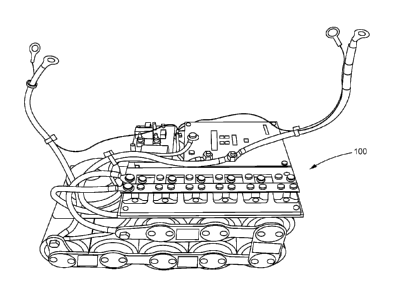
[0028] FIG. lA is a photograph of an example Engine Start and Battery Support
Module.
[0029] FIGS. 1B-C
are schematic diagrams illustrating example use of Engine Start and
Battery Support Module installed in a vehicle (e.g., a car or truck).
[0030] FIGS. 2A-B
show circuit diagrams depicting an overall master architecture for an
example Engine Start and Battery Support Module.
[0031] FIGS. 3A-C show several embodiments of a DC converter that may be used
in the
Engine Start and Battery Support Module to recharge a bank of expended
ultracapacitors.
[0032] FIGS. 3D-E show example features of the isolated DC converters of FIG.
3C.
[0033] FIG. 4 shows switches in an Engine Start and Battery Support Module for
switching
inter-cell connections between ultracapacitors from series connections to
parallel connections
and vice versa.
[0034] FIGS. 5A-B shows ultracapacitors arranged in a non-split (FIG. 5A) and
split (FIG.
5B) series configuration for usc in an Energy Start and Battery Support
Module.
[0035] FIGS. 6A-B show circuit diagrams of example direct current converters
that can be
used in the Engine Start and Battery Support Module.
[0036] FIG. 7 shows a flow diagram illustrating an example operation of an
Engine Start
and Battery Support Module.
DETAILED DESCRIPTION
[0037] Ultracapacitor-based engine cranking systems can be used to assist
vehicle battery
systems to crank when initiating an engine starting sequence. With these
systems, existing
vehicle wiring systems may be rerouted to create a direct connection from the
ultracapacitors
to the starter motor. In some cases, the ultracapacitors may be in parallel
with the vehicle
batteries. As the starting sequence is initiated, the ultracapacitors are
discharged, providing
7.
CA 02950151 2016-11-23
WO 2015/195321
PCT/US2015/033743
energy to spin the starter motor. After the engine is started, the vehicle's
altemator/generator
is used to generate electricity and thus recharge the ultracapacitors. This
system may also
include a DC/DC converter that recharges the ultracapacitors from the parallel
connected
batteries.
[0038] An Example Engine Start and Battery Support Module
[0039] FIG. 1 shows
an example ultracapacitor (UC)-based Engine Start and Battery
Support Module (hereinafter a "Module") 100 that can be used to assist a
vehicle battery
system during an engine starting sequence. The Module 100 shown in FIG. 1 is a
two-wire
system and can be included into any standard DC bus in parallel with any
number of
batteries. The Module 100 can be used to maintain a healthy DC bus voltage for
a vehicle that
is starting (e.g., by vehicle starter 101) or consuming a large load while
stopped. It may be
used to augment existing batteries 102 in vehicles, e.g., as shown in FIGS. 1B-
C, or as a
replacement for traditional lead acid batteries. Some of the advantages of
such a module are
that it can be installed safely and without special tools and may require
little or no wiring
changes to existing infrastructures.
[0040] In some embodiments, the Module 100 can include a bank of UCs that
supports both
engine 103 starting assistance and "hotel load" 104a support. The term "hotel
load" refers to
the non-driving energy demands on a vehicle, including energy use for lights,
air
conditioning, heating, computers, tracking systems, safety systems, etc.,
which are indicated
in FIG. IC as vehicle loads 104a and accessory loads 104b. When a vehicle's
engine 103 is
off, the vehicle's energy demands constitute the hotel load. The Module 100
can be used to
start a vehicle and/or to deliver energy back to the vehicle in a controlled
fashion to support
either the vehicle's static loads during short term stops and/or to supply
energy to get the
vehicle's electronics functioning, thus allowing the vehicle to start once the
engine 103 is
cranked. Examples of static loads during short stops may be the electronics,
air-conditioning,
lighting systems, etc., left on once the vehicle's engine 103 has stopped. In
some
embodiments, the static loads may include accessory loads 104b.
[0041] In some
embodiments, the Module 100 can be configured to address the
difficulty/inability of vehicles to start in adverse weather, under duress
from extremely weak
batteries, and/or from the effects of an excessively high number of engine
starts. Further, the
Module 100 enhances the health of the vehicle's battery 102 and starter motor
101 by
maintaining (e.g., increasing if it has fallen) the voltage on the vehicle's
direct current (DC)
bus 106, which comprises, for example, negative DC bus 106a and positive DC
bus 106b
(FIG. 1C), during short off times and cranking. For example, maintaining a
higher and/or
8.
CA 02950151 2016-11-23
WO 2015/195321
PCT/US2015/033743
more stable voltage allows for increases in the life of the batteries 102 and
the starter motor
101, in some cases dramatically.
[0042] In some embodiments, the Module 100 may be all solid-state. As
understood in the
art of electronic, solid-state components, including field-effect transistors
(FETs) and
insulated gate bipolar transistors (IGBT), tend to be faster, more reliable,
and consume less
power than relays and contactors. Further, the Module 100 may provide
capabilities to allow
a driver a manual "Redo" button that would start the transfer of energy from
the batteries 102
to the UCs. For example, this may be used in the situation where the vehicle
may not start the
first time. Such may allow the system to recharge on command even when the
alternator 105
is not running. While the duration-to-charge time may be longer, the net
result may be the
same. In addition, more and/or larger banks of UCs can be added to increase
the system's
total energy storage capabilities, for example, for an Auxiliary Power Unit
(APU).
[0043] In some
embodiments, the Module 100 can, physically and/or energetically, be
scaled to meet most or all applications. For example, the Module 100 can be
designed to fit
into battery group Battery Council International (BCI) size 31 (e.g.,
corresponding to heavy-
duty commercial grade batteries). In some embodiments, the overall shape can
be
approximately rectangular, and the two wires can correspond to the positive
and negative
battery terminals. In some embodiments, the Module 100 may be compatible with
existing
vehicle battery systems and may not require special installation methods,
tools, and/or safety
requirements, serving as a one size fits all type of architecture. For
example, the Module 100
can be designed to fit into housing that is a standard battery size, and can
also tie directly on
the bus. In some embodiments, the Module 100 can fit into a Group 31 size with
a height that
is slightly higher than the standard Group 31 battery or "bumped out" to
support 18 cells with
electronics. A newly tooled case can be used to maximize space as the Module
100 can be
lighter than a heavy lead battery. FIGS. 1B-C show schematic diagrams
illustrating example
use of Engine Start and Battery Support Module 100 installed in a vehicle.
[0044] Engine Start and Battery Support Module Architectures
[0045] FIGS. 2A-B show circuit diagrams depicting an overall master
architecture 200 for
an example Engine Start and Battery Support Module 100 with a two wire system
corresponding to a positive battery terminal 212a and a negative battery
terminal 212b. The
architecture 200 allows for independent adjustments of the voltage levels at
which hotel loads
and engine starts are supported, thus providing for variable energy delivery
depending on the
specific application and/or exact installation. The Module 100 is capable of
modulating the
transfer of energy between the UCs 201 and the system batteries 102 in both
directions. For
9.
CA 02950151 2016-11-23
WO 2015/195321
PCT/US2015/033743
example, the Module 100 recognizes when to deliver charge to keep batteries
102 alive for
short stops without the engine running. It also recognizes the static loads to
reset the
electronics in some applications prior to starting. In addition, it may
automatically connect
any remaining energy in the UC bank 201 directly in parallel to the batteries
102 during an
engine start, thereby keeping the system voltage above some determined lower
levels that
may cause premature battery and starter motor failures. In effect, it changes
the ESR of the
entire vehicles DC system. Different combinations of series and parallel cell
configurations
may be used depending on the amount of ESR to be used in comparison to hotel
load.
[0046] For example, the architecture 200 contains a serial string of UCs 201,
each of which
can be high specific capacitance electrochemical capacitor that stores energy
electrostatically.
A typical UC 201 has a capacitance value that is about 10,000 times that of an
electrolytic
capacitor, an energy density approximately 10% that of a conventional battery,
and a power
density up to 100 times that of the battery. This allows for a faster charge
and discharge
cycles for ultra-capacitors 201 compared to conventional batteries. It can
also give UCs 201
extremely long cycle lives compared to batteries.
[0047] Each UC 201
can be charged to a predetermined level of per cell voltage. As a
specific example, the UCs 201 may be charged to support 2.7 V/cell. The per-
cell voltage
value may be shifted automatically higher (e.g., 3.0 V/cell) when a low
temperature is
reached (e.g., 0 F) and even higher per-cell voltage (e.g., 3.3 V/cell) when
the temperature
falls even lower (e.g., below ¨20 F). In some embodiments, the temperature
may be
measured by a sensor 202. In some embodiments, each pack of UCs 201 may use a
DC/DC
converter (e.g., a 500 W DC/DC converter) 203 that can be settable in a
factory to a voltage
range, e.g., from 16.2 V to 24 V. The converter 203 may have either a boost or
single-ended
primary inductor converter (SEPIC) topography.
[0048] In some embodiments, the energy stored in the UCs 201 may be taken from
the DC
bus, and in some instances, it may be transferred directly back from the UCs
201 onto the
same DC bus, allowing for a controlled charging process of batteries 102 in a
vehicle.
Effectively, the Module 100 dynamically adjusts the Equivalent Series
Resistance (ESR) of
the vehicle's electrical system substantially constantly. In some embodiments,
the Module
100 comprises UCs 201 that may have significantly lower ESR than a typical
battery and
offer the ability to store energy quickly and to deliver the stored energy
back to the vehicle
with minimal interface based on the vehicle's changing needs both instantly
and/or on a
continuous basis. The lower the ESR of the UCs 201, the more efficient the
overall energy
transfer can be. The system can be scalable to the desired energy, which may
be dictated by
10.
CA 02950151 2016-11-23
WO 2015/195321
PCT/US2015/033743
the size of the vehicle and its "work flow." The Module 100, by modulating the
transfer of
energy from the UCs 201 back to the DC battery bus, delivers the desired
amount of energy,
instead of delivering too much energy (and wasting excess energy) or falling
short and not
delivering enough energy, as may happen when a module delivers a predetermined
amount of
power. In some embodiments, the modulation of the transfer of energy and/or
the charging
and/or discharging of UCs 201 may be controlled by a logic control 210 that
may be in
electrical communication with the DC converter 203 and the UCs 201, and can be
accomplished via FET 220. The Module 100 determines how to modulate the energy
transfer
based on variations in voltage and/or current caused by several variables,
including but not
limited to vehicle DC bus loads, starter motor sizes, battery age, wiring
conditions, battery
conditions, battery quantity, accessories, starter type, starter age, battery
type, temperature,
experience of the driver, etc.
[0049] For example,
the Module 100 may allow for energy to be drawn from otherwise
dead batteries over an extended period of time without further collapsing them
below a
destructive voltage level. For example, a lead-acid battery that is discharged
to a point where
its voltage is not high enough to start an internal combustion engine may
still possess enough
energy to completely charge one or more UCs (e.g., if the UC stores less
energy than the
battery). The Module 100 may charge the UCs 201 from the battery 102 using a
DC
converter 203 that controls both the current and voltage on both the input
side and the output
side of the UC 201 and battery 102 couple.
[0050] In
supporting the DC bus voltage of the vehicle's battery 102, in some
embodiments, the transfer of energy to the DC bus may be pulsed, e.g., by a
buck converter.
For example, the pulse may not be a fixed pulse-width modulation (PWM) 204 but
rather
may be at the natural frequency of the specific truck that it is installed in.
In short, energy
transferred from the UCs 201 to the battery 102 is based on the vehicle's
demand at that
moment. The recharge of the UCs 201 can be either pulsed if the cells are
divided to enable a
buck converter or recharged using a DC converter 203. In either case, the
total voltage on the
bank of UCs 201 may be actively adjusted both upwards and downwards depending
on some
parameter of interest, a particular example being the temperature in the
module, as measured
by a temperature sensor 202, for example. Such an embodiment may make
efficient use of
the potential energy that can be stored in each cell as well as extend the
life of the cells.
[0051] In some embodiments, the Module may recharge the UCs 201 when the
alternator
105 isn't running. The DC converter 203 may recharge the bank of UCs 201 by
transferring
the energy proportional to the vehicle's ability to deliver it. For example,
the Module 100
11.
CA 02950151 2016-11-23
WO 2015/195321
PCT/US2015/033743
may not take too much energy out of the batteries 102 that the batteries 102
would drain
below some lower limit potential (e.g., lower than 9 V). In addition, the
power transfer to
recharge the UCs 201 can be scalable using parallel combinations of controller
chips
arranged in a master and (many) slave organization where each controller
contributes an
additional phase worth of energy up to 12 phases. As such, a 250 W, 500 W, 750
W, etc.
charger could be used with little expense. In implementing multiple phases,
one phase
controls the master timing and the other "slave" phases are shifted by equal
intervals from the
master. The use of multiple phases allows the power transfer to be spread over
time, thus
effecting smaller peak currents and smaller more efficient components.
[0052] In some
embodiments, the UCs 201 can be charged primarily using the vehicle's
alternator 105 (shown in FIGS. 1B and 1C). In some embodiments, the UCs 201
can be
charged by drawing energy from the batteries 102 of the vehicle. The
recharging of the UCs
201 may be either automatic and can occur when the engine103 is running (i.e.,
alternator
105 is on) or it may be when commanded to do so during an emergency situation
where the
vehicle is without enough power to start on its own. For example, the Module
100 can power
up and reset itself automatically upon being connected into a live battery
system. For
example, if the Module 100 is connected in parallel to the battery system 102,
when the
vehicle is started, the alternator 105 charges the batteries 102 as originally
intended while the
Module 100 draws energy from the batteries 102. The Module 100 can balance the
voltage on
the power bus between the UC's 201 and batteries 102 until the UC's 201 have
reached
capacity.
[0053] In some
embodiments, each Module 100 may be able to operate in either an
automatic and/or manual mode, e.g., via the manual interface 214 shown in FIG.
2A. The
automatic mode may be utilized for delivery applications and very short haul
uses where the
number of engine starts per day are large, where it will be used to keep the
battery bus alive
for hotel support during a delivery stop. The manual mode may be utilized to
start the truck
where it will be used to energize the starter 101 with minimal energy used to
operate the
truck, enough to keep alive the electronics during a start sequence. In some
embodiments,
whether the Module 100 is in a manual mode or an automatic mode may be
controlled by a
switch 216 that, when turned on, allows the driver to engage the Module 100
via the manual
interface 214.
[0054] In the
automatic mode of operation, the energy is released initially slowly to
maintain a specified battery bus voltage until the UC bank 201 is expended.
When the bus
voltage equals the UCs voltage, the two systems are effectively in parallel
from then on. In
12.
CA 02950151 2016-11-23
WO 2015/195321
PCT/US2015/033743
the automatic mode, the actual battery bus voltage determines when the system
goes from
charging to neutral to discharging. When the mode of operation is manual, the
energy is
released slowly initially to maintain a specified battery bus voltage and then
when the UC
voltage equals the battery bus voltage the two systems are effectively in
parallel. In manual
mode, the Module senses an attempt to start the engine as indicated, e.g., by
a turn of the
ignition key or the voltage on a voltage meter on the instrument panel.
Otherwise this system
operates just like in the automatic mode except the beginning of the event is
triggered
intentionally. In the manual mode, the UC system does not lengthen the
starting sequence
and the driver starts the truck as normal.
[0055] Further, in some embodiments, the UCs. per-cell charge can be adjusted
and raised
during periods of low temperatures (e.g., less than 0 F) and even higher
during ultra-low
temperatures (e.g., less than ¨20 F). The raising of the cell voltage, which
can be dynamic
and/or automatic, may lead to an increase in the UC energy storage capability.
In addition,
some embodiments allow for the slow release of this energy based on the DC bus
voltage
using a pulse-width modulation (PWM) controller. The charging can be either
from an
onboard DC/DC converter 203, an alternating current (AC) hook up, and/or from
smartly
switching the banks of UCs 201 between parallel and serial connections.
[0056] The cell charging system has three characteristics, the -first being
where possible the
alternator 105 may be used to recharge the UCs 201 up to a predetermined
voltage, e.g.,
14.5 V. This may be accomplished using a FET 220 when the bus voltage is
higher than the
voltage across the UC bank 201. Second, above 14.5 V, each product can use a
500 W
DC/DC converter 203 that is settable in the factory to a desired voltage
range, e.g., from 16.2
V to 24 V. The converter 203 may be designed on a boost or SEPIC topography,
and is
capable of working down to 9 V in the event a future re-start option is
included. Third, when
the voltage on the pack reaches its predetermined set point, even when the
truck is off for
extended periods, the converter 203 may be designed to minimize its quiescent
current to
keep the overall system's drain low, yet with the dependability of being
available for a start at
any time. The current drain may be approximately 1 W per 100 kJ of stored
energy, once
charged, for example.
[0057] Cell balancing can be a clamping type in order to reduce or minimize
self-drain. It
can have temperature compensated set points with one or more distinct levels,
e.g., three
levels at 2.7 V, 3 V, and 3.3 V. In some embodiments, the voltage set points
may be
maintained at the DC system voltage regulator 230, e.g., the DC system voltage
regulator 230
may be set to match various ultracapacitor cell voltages for balancing. In
some cases, the
13.
CA 02950151 2016-11-23
WO 2015/195321
PCT/US2015/033743
balancing may be supplied by the ultracapacitors 201 and/or the DC system
voltage regulator
230 to reduce or minimize self-drain. In some embodiments, this compensation
may happen
automatically. In some embodiments, the cell balancing can be on the same
Printed Circuit
Board Assembly (PCBA) as the control logic 210 in FIG. 2A.
[0058] In the
exemplary implementations discussed herein and/or any other
implementations of the embodiments of the present technology, additional
features may be
available. For example, a smart user interface 107 could be included (e.g.,
connected to the
Module 100 via a cable as shown in FIG. 1B) to indicate to the driver the
status of the UC
pack 201 (e.g., UC power level). The smart user interface 107 may include LED
status
indicators or a "smart" UC fuel gauge display that indicate the status of the
UC pack 201. It
may also include "Redo" button that gives the driver the option to redo a
charge sequence.
Further, connections to the controller area network bus (CANbus) of the
vehicle could be
offered for better integration into the vehicle's system, in some cases by the
vehicle
manufacturer as an integral part of the built-in display.
[0059] In some embodiments, the energy in the Module 100 may be stored at a
level that is
higher than the nominal voltage on the bus and may then be released as desired
to support the
healthy DC bus voltage of a vehicle regardless of the static load 104 or even
during the
vehicle's starting sequence. In some embodiments, the vehicle starting event
may be
regarded as a big static load, and the Module's support of the DC bus may
cover both the
vehicle starting sequence and the static load. In these embodiments, rewiring
the vehicle or
delivering energy to the starter motor 101 may become unnecessary. The module
architecture
200 keeps the voltage stored in the UC bank 201 at a higher level than the
battery bus and
releases it slowly depending on the dip of that bus voltage due to load
changes. Pure DC is
pushed to the bus using a PWM buck converter with N-channel FETs 205
delivering the
power with an inductor sized for the hotel or truck electronics load only
after which it
saturates when the FETs 205 are on fully. The PWM 204 puts the UC bank 201 in
parallel to
the battery 102 when the PWM 204 reaches 100% on. The loop maintains a
predetermined
battery bus voltage level with a time response rated at >10 kHz.
[0060] In some embodiments, the Module 100 delivers energy directly to the DC
bus and
does so in an asynchronous way without (intentional) hysteresis. As such, even
during an
engine cranking, the system may maintain a voltage as close to a set point
(e.g., 12.5 V) as
possible even as the load of the system changes by a large factor (e.g., 1000
or more) during a
starting cycle. In some embodiments, the recharge may be multi-phase and
dynamic with
four quadrants being controlled allowing the system to adjust to the
environment, the state of
14.
CA 02950151 2016-11-23
WO 2015/195321
PCT/US2015/033743
charge of the UCs, and the system batteries. (Here, the term "quadrants"
refers to the current
and voltage control of the input and output of the converter.) Further, the
transfer of energy is
pulsed in variable amounts, thereby reducing pseudo Electro-Magnetic
Interference (EMI)
emitted from the module. The Module 100 acts very much like a frequency-
hopping radio in
this regard. The pulses may occur at a fixed repetition frequency or have
fixed pulse widths.
[0061] DC Converters for Recharging Ultracapacitors
[0062] FIGS. 3A-C show several embodiments of a DC converter 303 that may be
used in
the Module 100 to recharge the bank of UCs 301 when they arc expended. The
recharge may
occur in between start cycles and while the engine is running. Further, in
some embodiments,
the converters 303 may be used to charge the UC bank 301 initially when the
Module 100 has
been installed and to recharge the UC bank 301 when the batteries 302 and the
bank of UCs
301 are depleted either by extended vehicle off-time or when the vehicle will
not start after
the initial attempt(s). In such embodiments, the DC converter 303 may be able
to control the
input voltage cutoff so as not to ruin an otherwise depleted battery (e.g.,
when it is drawing
energy from the battery 302 to charge up the UCs 301), control both the input
and output
current in order to be able to charge nearly empty UCs 301, and/or control a
variable output
voltage set point in order to control the energy stored on the bank of UCs 301
as the
temperature varies.
[0063] Exemplary embodiments of DC converters 303 that can be used in the
Module 100
comprise enhancement mode (normally open) N-FETs that allow for the modulation
of the
transfer of power to a vehicle's DC bus. In some embodiments, the DC converter
303 may be
bi-directional, while in others it may not be bi-directional, but rather may
comprise separate
converters that regulate the transfer of power by monitoring the currents on
either side.
Further, in some embodiments, the DC converters 303 in the Module 100 may have
no
limitations as to how much energy can be transmitted on the delivery side. In
addition, they
may be scalable. For example, during an engine start the energy may be
transferred without
much delay and with as much energy as the UCs 301 have stored in order to keep
that DC
bus at some desired voltage (e.g., 12.5 V), which may effectively result in
the UCs 301 being
in parallel to the battery 302 in a starting sequence.
[0064] FIG. 3A
shows an example module architecture 300a coupled to a conventional
battery 302 in vehicle. The module includes a bank of UCs 301 connected in
series with a DC
voltage bus that is electrically connected to the battery's 302 positive
terminal and an isolated
DC converter 303a. The DC converter 303a may be electrically isolated as the
positive is
connected to the positive battery terminal (BAT+) through the inductor,
effectively changing
15.
CA 02950151 2016-11-23
WO 2015/195321
PCT/US2015/033743
its ground potential. In these embodiments, the control of voltage and current
on its input and
output may have to be transferred over the isolated barrier.
[0065] The ground side of the UC bank 301 is coupled to the drain side of a
set of N-FETs
305, which have sources coupled to the battery's 302 negative terminal and the
DC converter
303a. In some embodiments, the gates of the N-FETs 305 are coupled to the
output of a first
voltage comparator 306, which has an input coupled to the DC voltage bus. A
second voltage
comparator 307 has an input coupled to the DC voltage bus and an output that
enables or
disables the isolated DC converter 303a. In operation, the first voltage
comparator 306
compares the bus voltage to a set point voltage (e.g., 12 V) and triggers a
pulse from the UC
bank 301 whenever the bus voltage falls below the set point voltage, thereby
maintaining the
bus voltage at or above the set point voltage. The second voltage comparator
307 compares
the bus voltage to charge voltage (e.g., 13.5 V) and enables the DC converter
303a whenever
the bus voltage falls below the charge voltage. In response to the enable
signal, the DC
converter 303a charges the UC bank 301.
[0066] FIG. 3B shows a non-isolated DC converter 303b where the N-FETs 305 are
in the
high side and the DC converter 303b charges the "tops" of the UCs 301
maintaining a ground
connection all the time. This allows the DC converter 303b not to be isolated,
reducing the
cost of it significantly in both prototyping and production terms. In some
embodiments, the
drive circuit for the N-FETs 305 may have the gate-source voltage Vgate-source
to be at least
several volts (e.g., 10 V) higher than the source voltage Vsource (and in some
instances, the
Vsourcc may be BAT+). Since, in such embodiments, BAT+ may be sitting between
9 volts
and 14.5 volts above ground, this may cause Vgate-source to be approximately
24 volts, which
could result in the use of a small separate boost circuit. In some
embodiments, one may also
use isolated high side FET drivers that can switch this voltage level into the
high gate
capacitance for the parallel bank of N-FETS that may be used to deliver the
current during an
engine start. The exemplary embodiment shown in FIG. 3B has the advantages of
having
fewer connections and components.
[0067] FIG. 3C shows a system comprising two DC converters 303c and 303d,
where one
converter 303d is used to charge or recharge the bank of UCs and the other
converter 303c is
used to deliver the energy back to the DC bus. Each of these converters in
their "normal"
mode may have a set point that triggers the converter to turn on. For example,
to promote a
healthy battery, an exemplary 12.5 V set-point may be chosen to deliver energy
back to the
DC bus and a 13.75 V set-point to initiate a recharge cycle. Other set points
can be
determined differently as these are adjustable. However, the Module
architecture 300c also
16.
CA 02950151 2016-11-23
WO 2015/195321
PCT/US2015/033743
monitors the input and output currents. This feature allows the recharging of
the UCs 301 to
begin at times other than just when the alternator 105 is running, such as but
not limited to
when the batteries 302 are too weakened to perform a start and the bank of UCs
301 are
exhausted such as during an extended stop.
[0068] FIG. 3E and
FIG. 3D show details of some example features of the isolated DC
converters 303c and 303d, respectively. In some embodiments, these converters
may be bi-
directional, and in others, they may not be bi-directional. In the examples
shown in FIGS.
3D-E, the separate isolated converters regulate the transfer of power by
monitoring currents
on the charge input side (FIG. 3E) and the discharge output side (FIG. 3D).
[0069] As discussed
above, in some embodiments, a Module's energy may be stored in
UCs 201 that may be configured in series and/or parallel configurations. The
amount of
capacitance and/or the type of battery a Module 100 is compatible with may not
be restricted,
and in most embodiments, the voltage on the capacitors 201 may be higher than
the voltage
in the vehicle. The method of boosting the voltage can employ a conventional
boost style
converter that can be configured as a flyback, straight boost, or SEPIC, and
may be either
isolated or non-isolated. The converter can use a multi-phase approach to
minimize the peak
switching currents, which can in turn allow smaller, more efficient
components, better EMI
performance, and lower cost. In increments of a set amount of power (e.g., 250
W), more
phases can be added that may increase the recharge power level and reduce the
recharge time.
When each phase is added its switching frequency may intentionally be out of
phase with the
first switch.
[0070] Internal Ultracapacitor Connections for Charging and Discharging
[0071] FIG. 4 shows an embodiment depicting the changing of inter-cell
connections within
UCs 401 between series and parallel connections to accommodate a buck-only
charge and
discharge scheme is shown. In some embodiments, the UCs 401 may be recharged
by
splitting them up into equal banks of cells 401a and 401b where their fully
charged total
voltage is less than the vehicle's system. In some embodiments, the UCs 401
may be charged
by splitting the UCs 401 into several banks, each bank containing same and/or
different
number of UCs 401. In such embodiments, the UCs 401 can be recharged in a buck
mode
where energy is pulsed down to the caps. Such embodiments require more solid
state
switches and additional current control. When charged, the packs may be put
back in series
and readied for delivering power. In some embodiments, a series/parallel
switch 402 can split
the UCs 401 into two parallel banks 401a and 401b with equal numbers UCs 401
with total
voltages below the vehicle's system voltage, or connect them to form a single
UC bank with
17.
CA 02950151 2016-11-23
WO 2015/195321
PCT/US2015/033743
a total voltage above the vehicle's system voltage. In some embodiments, this
may allow a
single buck converter to be used for charging and discharging the UCs 401.
[0072] FIGS. 5A and 5B show converters 503 that can be used in some exemplary
methods
of charging the UCs 501 in the Module 100. FIG. 5A shows a separate and
dedicated non-
isolated DC converter 503a that boosts the voltage up to the UCs 501a during a
recharge
cycle. FIG. 5B shows splitting the cell stack in two 501b and 501c (e.g.,
equal halves each
containing half of total number of cells) and then buck charging each half in
parallel using the
vehicle's nominal DC bus as the point where the energy is taken from. In some
embodiments,
the vehicle's voltage may be higher than each of the split cells. The energy
may be pulsed in
a controlled manner to each stack in a buck mode concept. The switches 502
represent points
where the stacks are "put together" and then "separated" to accomplish this.
Once charged to
a given voltage, the two stacks are then put back in series for use in the
"delivery" mode, i.e.,
energy out mode. The mechanical switches 502 shown represent the "solid state"
switching
that may occur in real time.
[0073] In some embodiments, the switches 502 may be comprised of enhancement
mode
N-FETs and may carry the appropriate maximum current when connected in the
delivery
(energy out) mode (e.g., up to 2500 A). In some embodiments, the FETs can be
sized to
handle the charging current which may be in the range of 10-25 A. The
switching of FIG. 5B
may be less expensive and may provide for smaller electronics and allow for
the re-usage of
the on-board inductor in both directions. In some embodiments, the current
mode controller
may monitor and limit the root mean square (RMS) current that flows from the
vehicle's
battery to the two stacks of UCs 501b and 501c smartly and under most or all
circumstances
of the state of the charge on the capacitors. In some embodiments, more
capacitors 501, and
more stacks of UCs (e.g., 3, 4, 5, etc.) may be used, where each stack may
contain same
and/or different number of UCs.
[0074] In some embodiments, the DC converters shown in FIG. 5B can be utilized
to buck
switch the charging of the bank of UCs 501 by splitting the UCs 501 into two
equal stacks
501b and 501c, then recombining them in series when they are charged and
readied for use.
The splitting of the UCs 501 in two equal stacks may allow the UCs' fully
charged voltage to
be double when recombined (e.g., each is charged to 12.0 V, or 24.0 V when
recombined).
The example as shown in FIG. 5B includes four switch circuits 502a, 502b, 502c
and 502d
where two of those switches 502c and 502d may be capable of handling the high
currents
during an engine start and the other two 502 a and 502b can be sized smaller
as they are used
18.
CA 02950151 2016-11-23
WO 2015/195321
PCT/US2015/033743
to let charging currents pass through them. An example of a switch that can be
used is N-
FET.
[0075] In some embodiments of FIG. 5B, several N-FETs may be used to modulate
power
back to the DC bus. For example, if a Module 100 in a non-split configuration
(e.g., FIG. 5A)
includes ten N-FETs, the total number of N-FETs for split cell configuration
(e.g., FIG. 5B)
could increase to 22 N-FETs. In such embodiments, depending on the current
level, inductive
current sensing instead of standard current sense resistors may be used for
sensing high
current. Some embodiments may include one or more voltage sensors to measure
small
voltage drop across the inductor and then create the closed loop controls
around their values.
[0076] FIGS. 6A-B shows detailed circuit diagram schematics of exemplary DC
converters
that may be used in the Module. The DC converters can be multi-phase boost
converters
capable of delivering 250 W/phase with four-quadrant current and voltage
control on both the
input and output. This system can have an efficiency of approximately 95% and
can be single
phase. As each phase gets added, the power can increase proportionally. Each
successive
phase is intentionally "out of phase" with the preceding one by 360 /n where n
is the total
number of phases. This reduces the peak currents and keeps the component sizes
small. The
system may allow for faster recharge rates where these phases could be added
at the request
of the customer, or they may be proportional to the size of the vehicle where
the module is to
be installed.
[0077] Operation of an Engine Start and Battery Support Module
[0078] FIG. 7 shows
a flow diagram illustrating an example operating process for an
Engine Start and Battery Support Module 100. In some embodiments, the DC
converter may
be able to control or set the thresholds and maximum values for both the input
and output
voltages and current. Charging UCs 701 when they are empty may present a
problem in that
they may act like dead shorts, and unless the output current is sensed and
controlled the DC
converter may hiccup, collapse, or burn up. Setting an output current limit
should help
avoiding or limiting such complications.
[0079] In some embodiments, the output voltage setting may set the desired
voltage on the
UCs 701 and may be variable based on temperature in order to increase or
maximize the
capacitor's life and deliver the appropriate energy when desired, especially
in ultra-cold
environments. And the input current limit and minimum voltage can be useful in
avoiding the
collapse of the batteries 702 below their safe operating region (e.g., 9 volts
in a 12-volt
system) when the DC bus is being drained during a recharge recycle while the
alternator is
off In some embodiments, this function may be dynamic and the control may be
19.
CA 02950151 2016-11-23
WO 2015/195321
PCT/US2015/033743
proportional¨the more power is available for the recharge, the more power the
system (e.g.,
converter 703) may take. For example, at 9 volts, the power consumed by the
converter may
be zero, and at 13.75 volts the power may be 250 Watts for a single phase
system and for any
voltage in between, the power consumed may be proportionally in between 0
Watts and 250
Watts. In some embodiments, the converter may also have a quiescent current of
less than 25
mA when it is disabled which may be useful in maintaining overall system
performance.
[0080] Example Engine Start and Battery Support Modules
[0081] The
following non-limiting examples are intended to highlight aspects of Engine
Start and Battery Support Modules according to principles of the present
disclosure.
[0082] Example
device 1: Number of cells: eight in series; UC cell capacitance: 3000 F;
Total Capacitance: 375 F; Voltage: 21.6 V when the temperature is greater than
about 0 F
and 24 V when the temperature is less than about 0 F.
[0083] Example device 1 can provide "hotel load" support as a primary function
with the
secondary function being reserving energy for the actual starting sequence.
The ratio is
approximately 10:1 with the hotel load support getting more energy. The system
automatically supports a battery bus voltage from a string of UCs stacked in
series and
charged up to 2.7 V/cell or 3.0 V/cell depending on temperature. When the
voltage on the
cells equals the battery voltage they are then put in parallel by the design
of the architecture.
Exemplary application of this device is when vehicles are used for delivery.
[0084] Example device 2: Number of cells: two parallel strings of six cells
each in series;
UC cell capacitance: 3000 F; Total Capacitance: 1000 F; Voltage: 16.2 V when
the
temperature is greater than about 0 F and 18.0 V when the temperature is less
than about 0
F.
[0085] Example device 2 can deliver energy to crank the vehicle while
providing a reduced
or minimal amount of energy to keep alive the vehicle electronics during that
process.
Exemplary application of this device is when vehicles are used for capacitance
without
auxiliary power units.
[0086] Example device 3: Number of cells: three parallel strings of six cells
each in series;
UC cell capacitance: 3000 F; Total Capacitance: 1500 F; Voltage: 16.2 V when
the
temperature is greater than about 0 F and 18.0 V when the temperature is less
than about 0
F.
[0087] Example device 3 can deliver energy to crank the vehicle while
providing a reduced
minimal amount of energy to keep alive the vehicle electronics during that
process. This
20.
CA 02950151 2016-11-23
WO 2015/195321
PCT/US2015/033743
application supports delivering more energy for vehicle electronics during
vehicle starting
event, especially on vehicles where there are more than four batteries in
parallel. Exemplary
application of this device is when vehicles are used for capacitance with
auxiliary power
units.
[0088] Example device 4: Number of cells: three parallel strings of six cells
each in series
UC cell capacitance: 3000 F; Total Capacitance: 1500 F; Voltage: 16.2 V when
the
temperature is greater than about 0 F, 18.0 V when the temperature is less
than about 0 F,
and 19.8 V when the temperature is less than about ¨20 F.
[0089] Example
device 4 delivers increased or maximum energy to crank the vehicle in
ultra-low temperature applications.
[0090] Conclusion
[0091] While
various inventive embodiments have been described and illustrated herein,
those of ordinary skill in the art will readily envision a variety of other
means and/or
structures for performing the function and/or obtaining the results and/or one
or more of the
advantages described herein, and each of such variations and/or modifications
is deemed to
be within the scope of the inventive embodiments described herein. More
generally, those
skilled in the art will readily appreciate that all parameters, dimensions,
materials, and
configurations described herein arc meant to be exemplary and that the actual
parameters,
dimensions, materials, and/or configurations will depend upon the specific
application or
applications for which the inventive teachings is/are used. Those skilled in
the art will
recognize, or be able to ascertain using no more than routine experimentation,
many
equivalents to the specific inventive embodiments described herein. It is,
therefore, to be
understood that the foregoing embodiments are presented by way of example only
and that,
within the scope of the appended claims and equivalents thereto; inventive
embodiments may
be practiced otherwise than as specifically described and claimed. Inventive
embodiments of
the present disclosure are directed to each individual feature, system,
article, material, kit,
and/or method described herein. In addition, any combination of two or more
such features,
systems, articles, materials, kits, and/or methods, if such features, systems,
articles, materials,
kits, and/or methods are not mutually inconsistent, is included within the
inventive scope of
the present disclosure.
[0092] The above-described embodiments can be implemented in any of numerous
ways.
For example, embodiments of the present technology may be implemented using
hardware,
firmware, software or a combination thereof. When implemented in firmware
and/or
software, the firmware and/or software code can be executed on any suitable
processor or
21.
CA 02950151 2016-11-23
WO 2015/195321
PCT/US2015/033743
collection of logic components, whether provided in a single device or
distributed among
multiple devices.
[0093] In this respect, various inventive concepts may be embodied as a
computer readable
storage medium (or multiple computer readable storage media) (e.g., a computer
memory,
one or more floppy discs, compact discs, optical discs, magnetic tapes, flash
memories,
circuit configurations in Field Programmable Gate Arrays or other
semiconductor devices, or
other non-transitory medium or tangible computer storage medium) encoded with
one or
more programs that, when executed on one or more computers or other
processors, perform
methods that implement the various embodiments of the invention discussed
above. The
computer readable medium or media can be transportable, such that the program
or programs
stored thereon can be loaded onto one or more different computers or other
processors to
implement various aspects of the present invention as discussed above.
[0094] The terms "program" or "software" are used herein in a generic sense to
refer to any
type of computer code or set of computer-executable instructions that can be
employed to
program a computer or other processor to implement various aspects of
embodiments as
discussed above. Additionally, it should be appreciated that according to one
aspect, one or
more computer programs that when executed perform methods of the present
invention need
not reside on a single computer or processor, but may be distributed in a
modular fashion
amongst a number of different computers or processors to implement various
aspects of the
present invention.
[0095] Computer-executable instructions may be in many forms, such as program
modules,
executed by one or more computers or other devices. Generally, program modules
include
routines, programs, objects, components, data structures, etc. that perform
particular tasks or
implement particular abstract data types. Typically the functionality of the
program modules
may be combined or distributed as desired in various embodiments.
[0096] Also, data
structures may be stored in computer-readable media in any suitable
form. For simplicity of illustration, data structures may be shown to have
fields that are
related through location in the data structure. Such relationships may
likewise be achieved
by assigning storage for the fields with locations in a computer-readable
medium that convey
relationship between the fields. However, any suitable mechanism may be used
to establish a
relationship between information in fields of a data structure, including
through the use of
pointers, tags or other mechanisms that establish relationship between data
elements.
[0097] Also,
various inventive concepts may be embodied as one or more methods, of
which an example has been provided. The acts performed as part of the method
may be
22.
ordered in any suitable way. Accordingly, embodiments may be constructed in
which acts
are performed in an order different than illustrated, which may include
performing some acts
simultaneously, even though shown as sequential acts in illustrative
embodiments.
[0098] All definitions, as defined and used herein, should be understood to
control over
dictionary definitions, and/or ordinary meanings of the defined terms.
[0099] The indefinite articles "a" and "an," as used herein in the
specification and in the
claims, unless clearly indicated to the contrary, should be understood to mean
"at least one."
[0100] The phrase "and/or," as used herein in the specification and in the
claims, should be
understood to mean "either or both" of the elements so conjoined, i.e.,
elements that are
conjunctively present in some cases and disjunctively present in other cases.
Multiple
elements listed with "and/or" should be construed in the same fashion, i.e.,
"one or more" of
the elements so conjoined. Other elements may optionally be present other than
the elements
specifically identified by the "and/or" clause, whether related or unrelated
to those elements
specifically identified. Thus, as a non-limiting example, a reference to "A
and/or B", when
used in conjunction with open-ended language such as "comprising" can refer,
in one
embodiment, to A only (optionally including elements other than B); in another
embodiment,
to B only (optionally including elements other than A); in yet another
embodiment, to both A
and B (optionally including other elements); etc
[0101] As used herein in the specification and in the claims, "or" should be
understood to
have the same meaning as "and/or" as defined above. For example, when
separating items in
a list, "or" or "and/or" shall be interpreted as being inclusive, i.e., the
inclusion of at least
one, but also including more than one, of a number or list of elements, and,
optionally,
additional unlisted items. Only terms clearly indicated to the contrary, such
as "only one of'
or "exactly one of," or, when used in the claims, "consisting of," will refer
to the inclusion of
exactly one element of a number or list of elements. In general, the term "or"
as used herein
shall only be interpreted as indicating exclusive alternatives (i.e. "one or
the other but not
both") when preceded by terms of exclusivity, such as "either," "one of,"
"only one of" or
"exactly one of." "Consisting essentially of," when used in the claims, shall
have its ordinary
meaning as used in the field of patent law.
[0102] As used herein in the specification and in the claims, the phrase
"at least one," in
reference to a list of one or more elements, should be understood to mean at
least one element
selected from any one or more of the elements in the list of elements, but not
necessarily
including at least one of each and every element specifically listed within
the list of elements
23.
Date Recue/Date Received 2020-08-18
and not excluding any combinations of elements in the list of elements. This
definition also
allows that elements may optionally be present other than the elements
specifically identified
within the list of elements to which the phrase "at least one" refers, whether
related or
unrelated to those elements specifically identified. Thus, as a non-limiting
example, "at least
one of A and B" (or, equivalently, "at least one of A or B," or, equivalently
"at least one of A
and/or B") can refer, in one embodiment, to at least one, optionally including
more than one,
A, with no B present (and optionally including elements other than B); in
another
embodiment, to at least one, optionally including more than one, B, with no A
present (and
optionally including elements other than A); in yet another embodiment, to at
least one,
optionally including more than one, A, and at least one, optionally including
more than one,
B (and optionally including other elements); etc.
[0103] In the
claims, as well as in the specification above, all transitional phrases such
as
"comprising," "including," "can-ying," "having," "containing," "involving,"
"holding,"
"composed of," and the like are to be understood to be open-ended, i.e., to
mean including
but not limited to. Only the transitional phrases "consisting of' and
"consisting essentially
of' shall be closed or semi-closed transitional phrases, respectively.
24.
Date Recue/Date Received 2020-10-30