Language selection

Search

Patent 2950156 Summary

Third-party information liability

Some of the information on this Web page has been provided by external sources. The Government of Canada is not responsible for the accuracy, reliability or currency of the information supplied by external sources. Users wishing to rely upon this information should consult directly with the source of the information. Content provided by external sources is not subject to official languages, privacy and accessibility requirements.

Claims and Abstract availability

Any discrepancies in the text and image of the Claims and Abstract are due to differing posting times. Text of the Claims and Abstract are posted:

  • At the time the application is open to public inspection;
  • At the time of issue of the patent (grant).
(12) Patent: (11) CA 2950156
(54) English Title: REFRACTURING AN ALREADY FRACTURED BOREHOLE
(54) French Title: REFRACTURATION D'UN TROU DE FORAGE DEJA FRACTURE
Status: Granted
Bibliographic Data
(51) International Patent Classification (IPC):
  • E21B 43/26 (2006.01)
  • E21B 43/11 (2006.01)
  • E21B 43/114 (2006.01)
(72) Inventors :
  • RICHARD, BENNETT M. (United States of America)
  • WOOD, EDWARD T. (United States of America)
(73) Owners :
  • BAKER HUGHES INCORPORATED (United States of America)
(71) Applicants :
  • BAKER HUGHES INCORPORATED (United States of America)
(74) Agent: MARKS & CLERK
(74) Associate agent:
(45) Issued: 2022-06-14
(86) PCT Filing Date: 2015-06-04
(87) Open to Public Inspection: 2015-12-10
Examination requested: 2020-03-13
Availability of licence: N/A
(25) Language of filing: English

Patent Cooperation Treaty (PCT): Yes
(86) PCT Filing Number: PCT/US2015/034234
(87) International Publication Number: WO2015/187973
(85) National Entry: 2016-11-23

(30) Application Priority Data:
Application No. Country/Territory Date
14/298,287 United States of America 2014-06-06

Abstracts

English Abstract

A well with existing perforations is re-fractured by positioning isolators at locations offset from the existing perforations and perforating through those isolators. The isolators are part of a bottom hole assembly that can be delivered on coiled or rigid tubing. The initial fractures can be straddled by the isolators with no mandrel openings between them to effectively isolate the existing perforations as new perforations take place through the isolators. The elements of the isolators can have internal gaps to allow for axial shifting after perforation that is thermally induced. The gaps assure remaining alignment with the new perforations despite some axial shifting. The bottom hole assembly can alternatively have an anchor to resist thermally induced forces that can cause axial shifting.


French Abstract

L'invention concerne la refracturation d'un puits doté de perforations existantes en positionnant des isolateurs au niveau d'emplacements décalés des perforations existantes et en perforant à travers ces isolateurs. Les isolateurs font partie d'un ensemble de fond de trou qui peut être fourni sur une tubulure spiralée ou rigide. Les fractures initiales peuvent être chevauchées par les isolateurs, sans ouverture de mandrin entre elles, afin d'isoler efficacement les perforations existantes lorsque les nouvelles perforations ont lieu à travers les isolateurs. Les éléments des isolateurs peuvent avoir des espaces internes afin de permettre un décalage axial après perforation qui est induit par voie thermique. Les espaces garantissent le maintien de l'alignement avec les nouvelles perforations malgré un certain décalage axial. L'ensemble de fond de trou peut, de manière alternative, avoir un ancrage afin de résister aux forces induites par voie thermique pouvant provoquer un décalage axial.

Claims

Note: Claims are shown in the official language in which they were submitted.

What is claimed is:
1. A completion method for a previously operating borehole with
openings into a surrounding formation, comprising:
actuating against a wall of the borehole, at least one isolator disposed
upon a bottom hole assembly run into the borehole on tubing;
initially isolating from said tubing at least one existing perforation
with said isolator;
creating at least one new perforation through said isolator; and
flowing fluid between said tubing and said at least one new
perforation.
2. The method of claim 1, comprising:
anchoring said at least one isolator against axial shifting.
3. The method of claim 1, comprising:
allowing said at least one isolator to axially shift in response to
thermal loading.
4. The method of any one of claims 1 to 3, comprising:
providing at least one internal axial gap in said at least one isolator
in fluid communication with a mandrel supporting said at least one isolator.
5. The method of claim 4, comprising:
providing a plurality of axial gaps as said at least one gap in said at
least one isolator;
creating a plurality of new perforations as said at least one new
perforation through said at least one isolator; and
allowing flow between said tubing and said plurality of new
perforations through said at least one isolator through said gaps.
6. The method of claim 5, comprising:
spacing said plurality of axial gaps equally or unequally.
Date Recue/Date Received 2021-08-23

7. The method of claim 1, comprising:
using a plurality of spaced isolators on a mandrel as said at least one
isolator;
providing a plurality of existing perforations as said at least one
existing perforation; and
straddling said plurality of existing perforations with said plurality
of spaced isolators to preclude access to said tubing from said plurality of
existing perforations.
8. The method of any one of claims 1 to 3, comprising:
using at least one perforating gun within a mandrel of said at least
one isolator to produce said at least one new perforation.
9. The method of any one of claims 1 to 4, comprising:
using a swelling packer or a mechanically or hydraulically actuated
packer as said at least one isolator.
10. The method of any one of claims 1 to 9, comprising:
using coiled or rigid tubing for said tubing.
11. The method of any one of claims 1 to 4, comprising:
fracturing said at least one new perforation.
12. The method of claim 11, comprising:
reopening said at least one existing perforation after fracturing said
at least one new perforation.
13. The method of claim 12, comprising:
flowing to said at least one existing perforation and at least one new
perforation at the same time.
14. The method of any one of claims 1 to 4, comprising:
using said at least one isolator to shield said at least one new
perforation from borehole fluids.
6


Description

Note: Descriptions are shown in the official language in which they were submitted.


CA 02950156 2016-11-23
WO 2015/187973
PCT/US2015/034234
REFRACTURING AN ALREADY FRACTURED BOREHOLE
FIELD OF THE INVENTION
[0001] The field of the invention is creating new fractures in previously

fractured boreholes in locations offset from the existing fractures.
BACKGROUND OF THE INVENTION
[0002] Wells that have been initially perforated and then the
perforations
fractures eventually experience a falloff in production or start to produce
sand,
water or other undesirable materials. In an effort to salvage additional
production from such wells, past techniques have involved sealing off the
perforations and perforating the borehole wall in other locations. The
plugging
of the existing perforations was done with chemicals that get into the
perforations and solidify or harden to close them off. The problem with such
systems is the uncertainty of distribution of the material which could leave
some of the existing perforations open. Another way of closing the existing
perforations is to have adjacent sliding sleeves that could be moved with a
shifting tool to close the existing perforations. Some issues with this method

are high initial cost, the cost of the trip to operate the sleeves and the
uncertainty of whether the sleeves will actually shift to a closed position or
get
hung up on spurs or burrs caused by the original perforating. Other ideas have

included sleeve placement over existing perforations but such a method has
associated costs of placing the sleeves and some uncertainties that the
placement location will cover the intended perforations and even if there is
coverage of the intended perforations whether the cover will be effective as a

seal to close off such openings.
[0003] The uncertainties of past methods are addressed by the present
invention where a string of isolators straddles the existing perforations and
where no openings in the mandrel between the isolators are to be found. In
this
manner the existing perforations are effectively isolated so that new
perforations can be made by then perforating from within the mandrel and
through the isolators to open new perforations that remain isolated from the
existing perforations by virtue of the fact that the new perforations were
started through the isolators. The bottom hole assembly can be delivered on
coiled tubing or rigid pipe and can feature an anchor to prevent axial
shifting
1

due to borehole thermal effects. Such shifting could result in closing of the
newly made perforations. An alternative way to address axial shifting is to
provide internal spaces in each seal assembly so that even if there is axial
shifting after firing there will still be enough new perforations aligned with
such
spaces in the barrier element so that adequate flow rates can be obtained
without
undue pressure drop.
[0004] Perforating through cement inflatable packers for initial well
production has been discussed in Suman USRE 30711.
[0005] The above described features and others will be more readily
apparent from a review of the description of the preferred embodiment and the
associated drawings while recognizing that the full scope of the invention can

be determined from the appended claims.
SUMMARY OF THE INVENTION
[0006] A well with existing perforations is re-fractured by positioning
isolators at locations offset from the existing perforations and perforating
through those isolators. The isolators are part of a bottom hole assembly that

can be delivered on coiled or rigid tubing. The initial fractures can be
straddled
by the isolators with no mandrel openings between them to effectively isolate
the existing perforations as new perforations take place through the
isolators.
The elements of the isolators can have internal gaps to allow for axial
shifting
after perforation that is thermally induced. The gaps assure remaining
alignment
with the new perforations despite some axial shifting. The bottom hole
assembly
can alternatively have an anchor to resist thermally induced forces that can
cause axial shifting.
2
Date Recue/Date Received 2021-08-23

[0006a] Accordingly, in one aspect there is provided a completion method
for a previously operating borehole with openings into a surrounding
formation,
comprising: actuating against a wall of the borehole, at least one isolator
disposed upon a bottom hole assembly run into the borehole on tubing;
initially
isolating from said tubing at least one existing perforation with said
isolator;
creating at least one new perforation through said isolator; and flowing fluid

between said tubing and said at least one new perforation.
BRIEF DESCRIPTION OF THE DRAWINGS
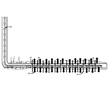
[0007] FIG. 1 is a schematic overview of the existing and new
perforations
that are offset from each other;
[0008] FIG. 2 is a view of an isolator with an anchor where the
perforating
is through the isolator;
[0009] FIG. 3 shows a problem of misalignment after perforating that can

happen due to thermally induced axial forces;
[0010] FIG. 4 shows gaps in the isolator element that allow for some
thermally induced axial shifting while still maintaining alignment to the new
perforations;
2a
Date Recue/Date Received 2021-08-23

CA 02950156 2016-11-23
WO 2015/187973
PCT/US2015/034234
[0011] FIG. 5 is the view of FIG. 4 showing the alignment that still
exists
despite thermally induced axial shifting when no anchor is employed.
DETAILED DESCRIPTION OF THE PREFERRED EMBODIMENT
[0012] FIG. 1 shows a borehole 1 that is cemented with cement 2 although
an open hole is also contemplated. The wide arrows 10 represent the original
perforations in the borehole 1 and the narrower arrows 5 represent the
recompletion perforations that are offset from the original perforations
represented by arrows 10. The delivery string can be coiled or threaded tubing

20 that further includes a series of spaced isolators such as 22 and 24.
Narrow
arrows 5 are shown as going through the isolators such as 22 and 24. Intervals

such as 26 preferably have no openings so that the openings represented by
wide arrows 10 are effectively isolated when the new perforations represented
by arrows 5 are put into service for production or injection. Optionally, the
existing perforations represented by arrows 10 can be re-accessed after the
creation and fracturing of the new perforations represented by arrows 5.
[0013] FIG. 2 illustrates a typical isolator 30 that can be a swelling
packer
or one that is set mechanically or hydraulically. The isolator 30 is supported

on a mandrel 32 that is at the end of tubing 20. A gun 34 can be positioned
within the mandrel 32 adjacent to one or more isolators 30 with the idea that
the perforations 36 are created through the element 30. One or more anchors
38 can be provided adjacent one or more isolators 30. The anchor can be a
known construction and is used to prevent or limit axial movement after
perforation through the isolator 30 which could cause a misalignment between
the openings made in the isolator 30 and in the formation. "fhis possibility
is
illustrated in FIG. 3 where there is no anchor 38 and thermal loads have
resulted in shifting of the perforated isolator 30 so that openings 40 made
with
the gun that was shot earlier are now axially offset from the perforations 36
that were newly made. Arrow 42 illustrates the thermally induced axial
movement that can cause the misalignment shown in FIG. 3.
[0014] FIG. 4 is an alternative embodiment where at least one anchor such

as 38 is not employed but provisions are made to have passages such as 44
preformed in the isolator 30 so that the firing of the gun is through the
solid
segments 46 to create the perforations 36. Arrows 48 in FIG. 5 show that paths
3

CA 02950156 2016-11-23
WO 2015/187973
PCT/US2015/034234
to the perforations 36 still exist despite thermally induced axial shifting of
the
mandrel 32 there are still open paths to the formation 36.
[0015] Those skilled in the art will now appreciate that the perforating
through the isolators will allow the new perforations to be in direct
communication with the mandrel for the isolator so that production or
injection can take place with the existing perforations isolated. The
fracturing
of the new perforations preferably takes place with the existing perforations
isolated. However, after such fracturing the original perforations can be
reopened with sliding sleeves in the mandrel for the isolators or by further
perforating or by other methods to open access to the original perforations.
It
is preferred to isolate the original perforation during the fracturing of the
new
perforations so that all the fracturing fluid can go where most needed into
the
new perforations. The isolators can be anchored against thermally induced
forces that can shift the already perforated isolator elements from the
freshly
made formation perforations. Alternatively the axial movement can be
tolerated and the element for the isolators can be built with enough gaps that

are presented in a repeating or random spacing pattern so that even after
shooting through the solid portions of the isolator and tolerating later
shifting
of the isolator in an axial direction there will still be open paths to the
formation perforations through the left open portions of the isolator. the
open
portions of the isolator are preferably internal to the isolator assembly so
that
if there is axial shifting and flow though the isolated openings in the
element
that there will be portions of the element to define closed paths to the newly

made perforations.
[0016] The above description is illustrative of the preferred embodiment
and many modifications may be made by those skilled in the art without
departing from the invention whose scope is to be determined from the literal
and equivalent scope of the claims below:
4

Representative Drawing
A single figure which represents the drawing illustrating the invention.
Administrative Status

For a clearer understanding of the status of the application/patent presented on this page, the site Disclaimer , as well as the definitions for Patent , Administrative Status , Maintenance Fee  and Payment History  should be consulted.

Administrative Status

Title Date
Forecasted Issue Date 2022-06-14
(86) PCT Filing Date 2015-06-04
(87) PCT Publication Date 2015-12-10
(85) National Entry 2016-11-23
Examination Requested 2020-03-13
(45) Issued 2022-06-14

Abandonment History

There is no abandonment history.

Maintenance Fee

Last Payment of $277.00 was received on 2024-05-21


 Upcoming maintenance fee amounts

Description Date Amount
Next Payment if standard fee 2025-06-04 $347.00
Next Payment if small entity fee 2025-06-04 $125.00

Note : If the full payment has not been received on or before the date indicated, a further fee may be required which may be one of the following

  • the reinstatement fee;
  • the late payment fee; or
  • additional fee to reverse deemed expiry.

Patent fees are adjusted on the 1st of January every year. The amounts above are the current amounts if received by December 31 of the current year.
Please refer to the CIPO Patent Fees web page to see all current fee amounts.

Payment History

Fee Type Anniversary Year Due Date Amount Paid Paid Date
Application Fee $400.00 2016-11-23
Maintenance Fee - Application - New Act 2 2017-06-05 $100.00 2017-05-08
Maintenance Fee - Application - New Act 3 2018-06-04 $100.00 2018-05-10
Maintenance Fee - Application - New Act 4 2019-06-04 $100.00 2019-05-23
Request for Examination 2020-06-04 $800.00 2020-03-13
Maintenance Fee - Application - New Act 5 2020-06-04 $200.00 2020-05-25
Maintenance Fee - Application - New Act 6 2021-06-04 $204.00 2021-05-19
Final Fee 2022-04-19 $305.39 2022-03-22
Maintenance Fee - Application - New Act 7 2022-06-06 $203.59 2022-05-18
Maintenance Fee - Patent - New Act 8 2023-06-05 $210.51 2023-05-24
Maintenance Fee - Patent - New Act 9 2024-06-04 $277.00 2024-05-21
Owners on Record

Note: Records showing the ownership history in alphabetical order.

Current Owners on Record
BAKER HUGHES INCORPORATED
Past Owners on Record
None
Past Owners that do not appear in the "Owners on Record" listing will appear in other documentation within the application.
Documents

To view selected files, please enter reCAPTCHA code :


To view images, click a link in the Document Description column. To download the documents, select one or more checkboxes in the first column and then click the "Download Selected in PDF format (Zip Archive)" or the "Download Selected as Single PDF" button.

List of published and non-published patent-specific documents on the CPD .

If you have any difficulty accessing content, you can call the Client Service Centre at 1-866-997-1936 or send them an e-mail at CIPO Client Service Centre.


Document
Description 
Date
(yyyy-mm-dd) 
Number of pages   Size of Image (KB) 
Request for Examination 2020-03-13 4 102
Examiner Requisition 2021-04-29 3 152
Amendment 2021-08-23 10 361
Claims 2021-08-23 2 64
Description 2021-08-23 5 210
Final Fee 2022-03-22 4 116
Representative Drawing 2022-05-18 1 7
Cover Page 2022-05-18 1 43
Electronic Grant Certificate 2022-06-14 1 2,527
Abstract 2016-11-23 1 69
Claims 2016-11-23 3 68
Drawings 2016-11-23 3 58
Description 2016-11-23 4 187
Representative Drawing 2016-11-23 1 12
Cover Page 2016-12-13 1 42
International Search Report 2016-11-23 2 88
Declaration 2016-11-23 2 60
National Entry Request 2016-11-23 3 85