Note: Descriptions are shown in the official language in which they were submitted.
CA 02950508 2016-12-02
=
COMPACT VIBRATION REDUCING HUMAN SUPPORT
Field of the Invention
[0001] The present invention relates in general to how to
support human bodies in
environments that are vibrating, and in particular to supports with active
vibration
cancellation that can be compact, lightweight and efficient.
Background of the Invention
[0002] Vibration is a known problem for human operators,
users, passengers, etc. of
equipment and vehicles. It is known to dampen vibration with passive, active,
or semi-
active damping techniques. These techniques have different merit for different
problems,
but generally, for high levels of vibration reduction, active control is
required. This is
essentially because passive damping generally lacks sufficient absorption
efficiency,
even over a narrow range of frequencies and moderate amplitudes. Passive
damping
also lacks adaptivity: a mass and spring of a given frequency, cannot adapt
itself to an
input force of changing frequency. Semi-active solutions are adaptive to
changing
frequencies, but generally reduce vibration less than desired, even if
feedback and
control are perfectly tuned.
[0003] Systems for vibration suppression of rotary-wing
aircraft are specifically
discussed in the literature. A variety of active or semi-active and passive
systems are
known. Helicopter vibration control has been examined at the source (rotor)
with passive
and active blade vibration control, as well as local solutions with passive
damping and
semi-active damping of seats. The vibration control of local structures such
as the trim
panels, seat structures and the seat cushions are tempting because these
systems are
subject to fewer certification requirements, offering easier implementation,
as well as
lower weight penalties [9] than rotor-local vibration suppression strategies.
[0004] Neck strain and back injuries are common health
problems among, for
example, the pilots and co-pilots of rotary-wing aircraft [1, 8]. Vibration
from the blades
through the fuselage to the human body has been found to create a wide range
of health
issues: from short term effects such as discomfort and fatigue to long term
effects like
chronic pain and spinal misalignment [1, 8].
[0005] All vibration frequencies are not equally harmful
for humans, and it is far easier
to design a system that improves a narrow range of vibration frequencies, than
one that
suppresses vibrations effectively across a wide spectrum. For instance,
Hiemenz et al.
1
CA 02950508 2016-12-02
[7] integrates two MagnetoRheological Fluid (MRF) dampers on the side columns
of a
SH-60 Seahawk crew seat. MRF dampers are "semi-active" vibration control
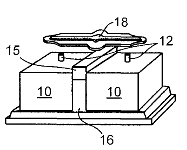
systems,
because they are given feedback to respond to current load conditions, but do
not supply
any force to counter the vibration in response, but rather change the damping
properties
of the dampers to increase the absorption of the materials given the current
dynamics.
MRF dampers rely on a material that is sensitive to magnetic field changes,
and a field
generator. While MRF dampers generally have lower energy consumption than
active
control strategies, they may be wanting in efficiency of damping.
[0006] Using experimental test results, Hiemenz et al. shows that the new
system
reduced the dominant rotor-induced vertical vibration (4/rev) by 76% for a
50th percentile
male aviator. However, the 76% reduction in the 4/rev component does not
result in a
desired level of improvement on the pilot's comfort or well-being, mainly
because the
human body is less sensitive to the 4/rev component than lower harmonics,
especially
1/rev. Although the transmissibility of the modified Seahawk seat is
considerably reduced
for medium and high frequency ranges (above 8 Hz) such as 4/rev component, it
does
not show significant improvements for the lower frequency range (between 0.5
Hz to 8
Hz) where the 1/rev excitation is expected. In some cases, the
transmissibility of the
modified seat is even higher than the unmodified seat in the lower frequency
range.
Furthermore, it should be noted that integrating the MRF dampers into the
structure of the
seat requires modification and certification of the existing seats for every
type of
helicopter.
[0007] As another example in the helicopter vibration context, consider
various pilots
with different weights using a same seat cushion system. Chen et al. [2, 3]
evaluate the
performance of different seat cushion materials for mitigating whole body
vibration (WBV)
exposure in a Bell-412 helicopter. It is demonstrated that the use of a
meticulously
designed cushion reduces the vibration level by 24.9% in terms of health risk
for a 50th
percentile pilot, but it only reduces vibration level by a value of 0.2% for a
85th percentile
co-pilot. While this study was limited to a passive system, it illustrates the
difficulties
inherent in the problem.
[0008] Active control feedback systems have known advantages in terms of
damping
efficiency, and rely on sensors, feedback electronics and a power supply. The
main
function of active systems is to add energy to the system by applying a time
varying force,
with a same magnitude as an observed force, but opposite in phase. The applied
forces
are usually generated using such active elements as pneumatic, hydraulic,
piezo-electric
or electromechanical actuators, and they require a relatively large amount of
power to
2
CA 02950508 2016-12-02
operate compared with passive or semi-active devices. While the design of
active control
systems is research-intensive and costly, it demonstrates a better performance
than
passive or semi-active control systems.
[0009] Chen et al. [4-
6] integrated two types of actuators into the helicopter seat
structure to dampen unwanted vibration: an electromechanical motor and a piezo-
electric
actuator. In both cases, significant reduction in vibration level is achieved,
for instance, in
the latter case, it is reported that overall 26% vibration reduction at the
pilot helmet
location is achieved. Despite the
fact that the active seat performance showed
improvement in the overall vibration, major areas of improvement were
identified:
= The active control results did not show any appreciable reduction to the
low
frequency vibration, namely, 1/rev harmonic.
= The active seat design does not comply with the crashworthiness
requirements of
helicopter seats.
= The piezo-electric actuator lacked a displacement suitable to cancel
vibration
amplitudes observed.
= The bulky size of the electromechanical motor was an undesirable aspect
of this
type of actuator, and is better suited to lab testing than deployment in
aircraft.
[0010] US2013/0180350
to Kraus et al. teaches an active bearing for vibration
reduction. The active bearing preferably includes a support element for
supporting a
static load transfer. The support element "typically comprises a suspension
spring
element or a plurality of suspension spring elements" that is "preferably
produced from a
material with small damping capacity so that the best possible insulation
effect is enabled
between vibrating load 8 and support unit 6 at high excitation frequencies".
In the
embodiment of FIG. 4, the support element is an elastomer molded body that
acts as a
spring. It is understood that some elastomeric materials behave as springs in
their
response, while other elastomers are much more like dampers, and visco-elastic
materials are somewhere between these extremes. The teachings here suggest the
substitution of a suspension spring element with an equivalent elastomeric
spring. A
dashpot or damper is used to decouple the support element 3 from the dynamic
load
bearing (force path II). The encasing of an active element for counteracting a
dynamic
load, with a passive element for transmitting a static load, is shown in FIG.
4.
[0011] US
2013/0328253 (`253) is addressed not to a support for specifically
suppressing 0.5-8 Hz vibrations, but to a system for suppressing all
vibrations that
interfere with atomic force microscopes, electron microscopes, etc. The
teachings
include an intermediate mass that is isolated in 6 DoF, and has a plurality of
voice coil
3
CA 02950508 2016-12-02
motors, passive dampers, and springs along different axes to isolate an
intermediate
mass from the sprung mass and the floor, in order to improve vibration
reduction at the
sensitive equipment. "Voice coil motors" include a very wide range of devices,
from
devices in headphones to devices that simulate vibrations of rockets. Given
that '253 is
directed to avoiding the "small payload vibrations" to which such instruments
are "very
sensitive" (clearly nobody would put such sensitive equipment in a high
amplitude
vibration environment that would be of any concern to a human occupant), and
given that
a "small and inexpensive actuator" is preferred, it is submitted that a small
voice coil
motor is inherent to this application. At [0006] the patent does not indicate
that the
extremely small displacement of piezoelectric actuators is problematic, but
that voice coil
motors can be used unlike the suggestion in US 5,660,255 to reduce cost. Small
and
inexpensive voice coil motors are beneficially compact, but are not powerful
enough to
effectively drive higher amplitude vibrations encountered in many
applications, even if
such voice coil motors are likely sufficient to cancel noise in a generally
quiet lab for
operating such scientific equipment.
The addition of an intermediate mass, with
clearances required for its movement, and the multiplication of joints, makes
compactness a problem, even if the design could be modified to provide the
force and
actuation length required for application in noisier environments.
= [0012] Patent applications, such as US 2014/0263932 and US
2013/0092814 show
active vibration cancellation systems with a spring and an actuator with
suitable linkages
that appear to be compact and suitable for deployment under a seat.
Suitability for
suppressing 0.5-8 Hz vibrations is not considered or discussed, and is not
inferable.
[0013]
In rotorcraft seats, as in many stations for operating, monitoring, or
supporting
people near, vibrating equipment, there is a need for a compact, lightweight,
active
system for cancelling vibrations.
Summary of the Invention
[0014]
Applicant has discovered a surprisingly effective vibration reduction
system
(VRS) having active and passive components. The VRS is remarkably compact and
suitable for deployment in a wide variety of conditions. As can be seen from
the survey of
patent literature in the background of the invention, the use of dampers or
dashpots in
parallel with active vibration control is not prevalent in the art, especially
where a force
amplitude of the vibrations is high. This may be because the dampers resist
the actuator
just as much as they passively suppress vibrations: the actuator has to
counteract the
damper prior to delivering any canceling vibrations, which effectively
decreases the power
4
CA 02950508 2016-12-02
of the actuators. Adding size and weight by use of higher power actuators are
generally
to be avoided.
[0015] The VRS comprises a ground, a frame for carrying a support structure
adapted to support a live human, at least one motor actuator path between the
ground
and frame adapted to cancel vibrations in at least one direction, and for each
of the at
least one directions, a parallel path consisting of an elastomeric damping
body (EDB)
between the ground and frame, the EDB positioned so that elastic restorative
forces are
oriented in the respective direction. No other path is provided to couple
between the
ground and frame in the at least one direction, at least under normal
operating conditions,
or when active vibration control is being applied by the VRS. The VRS includes
a means
for sensing vibrations and for forwarding feedback to a controller of the
actuator.
[0016] The use of an EDB in accordance with the present invention is not a
simple
substitute for dampers, or a spring with a damper: they provide substantial
advantages for
designing and assembling compact VRSs, which is especially important when a
number
of degrees of freedom of the vibration to be damped is 2 or more, or stringent
controls are
placed on size and weight of the VRS. Furthermore, a shape factor of the EDB
(defined
herein as a selection of a geometry of the elastomer to control both the
amount of
elastomer between ground and support, as well as the free space into which the
elastomer may bulge or extend) allows for tuning of elastic and damping
characteristics of
the material. Like both springs and dampers, the shape of EDB can be arranged
to
exhibit very high stiffness in all degrees of freedom but one, to make sure
the VRS is
stable, but they can do so in a much more compact arrangement as the EDB does
not
require a prismatic joint or other shock absorber type structure.
[0017] The EDB is preferably selected so that a static deflection under the
anticipated
load of 5-25%, more preferably 7-14%, preferably 10% is provided, so that when
the VRS
is operating, the actuator has a limited resistance profile from the EDB over
a full range of
the actuator. The EDB has some elastic behavior as well as some absorption
behavior
that may not be exactly proportional to velocity. It will be appreciated that
EDBs typically
exhibit a loss of linearity that is more pronounced at high deformation.
Preferably,
throughout a displacement range of the actuators the EDB remains substantially
linear.
Alternatively accurate operation in this regime is possible with
characterization of the
material in this regime that is not subject to degradation or aging, for an
intended duration
of deployment.
CA 02950508 2016-12-02
[0018] Applicant has found that use of an EDB, with some spring action but
mostly
damper action (e.g. a resilience rebound height of less than 40, more
preferably 3 to 30,
more preferably 5 to 15), = can bear a static component of the supported load,
while
facilitating the actuator to perform active vibration cancellation provides a
remarkable
improvement over known designs, and improves a form factor of the system. The
use of
an EDB makes it practical, for the first time, to use a VRS in a host of
applications where
they were needed, but not believed to be cost efficient.
[0019] Accordingly, vibration reduction system VRS is provided, the VRS
comprising
a grounding for fixing the VRS to a vibrating environment; a frame for
carrying a support
structure suitable for supporting a live human; a plurality of displacement
actuators, each
having a stator end, an actuator end, and a displacement extension range in a
direction
associated with the respective actuator, with each of the actuators having one
of the
stator end and actuator end affixed to the frame, and the other to the
grounding; one or
more elastomeric damping bodies (EDBs) composed of a material having a dynamic
Young's Modulus of 0.1-2.5 MPa, and a resilience test rebound height less than
40,
positioned between the grounding and frame to provide elastic restorative
forces and
damping in each of the respective directions; and no other path to couple the
ground to
the frame in any of the respective directions under normal operating
conditions of the
VRS.
[0020] The grounding may comprise a bracket for retaining a casing of at
least one of
the actuators, wherein the bracket: surrounds at least one of the plurality of
actuators; is
composed of an assembly of separate parts; is adjustable for a size, weight or
feature of
the live human; is releasably mountable to the grounding, frame or one or more
EDBs; or
is reconfigurably mountable to the grounding, frame or one or more EDBs in two
or more
arrangements.
[0021] A first of the at least one EDBs may be mounted on one side to a
wall of the
casing, which squarely faces an opposite wall of one of the grounding
structure and frame
to constrain the EDB, whereby the casing is part of the frame or grounding
structure.
[0022] The bracket may have a surface, and a first of the at least one EDBs
may be
mounted on one side to the bracket surface, which squarely faces an opposite
wall of one
of the grounding structure and frame to confine the EDB. The first EDB alone,
or with
one or more of the at least one EDBs, is arranged so that the EDB rotationally
symmetrically surrounds the actuator end of the first actuator, or the first
EDB's axis is
collinear with the direction of the first actuator.
6
CA 02950508 2016-12-02
[0023] The VRS of any one of claims 1 to 4 where the axis of the first EDB
is parallel
to both first and second actuators of the plurality of actuators, and the
first EDB alone, or
with one or more of the at least one EDBs, are arranged to lie: symmetrically
between the
first and second actuators, symmetrically around the first and second
actuators; or both.
[0024] The first and second actuators may be: aligned to a common plane and
the
symmetry is rotational symmetry about a centre of the first and second
actuators in this
plane; or oriented oppositely and offset by 0.5-1 times a width of the first
and second
actuator bodies in an offset direction that is perpendicular to the direction
of the first and
second actuators, and the symmetry is rotational symmetry about a centre of
the first and
second actuators in a plane spanned by the offset direction and the direction
of the first
and second actuators.
[0025] The VRS may further comprise a sensor sensitive to vibrations and a
feedback
circuit for controlling motors of the plurality of actuators.
[0026] The actuation directions of the plurality of the actuators may span
1, 2 or 3
Cartesian directions. An equal number and power of the actuators may be
provided in
each actuation direction, and each EDB may have an equivalent absorption
profile.
Alternatively a higher number of actuators or higher power actuators are
disposed in
directions of greatest vibration amplitudes, or in directions where vibrations
are more
injurious to an occupant.
[0027] The one or more EDBs preferably have a shape factor to control
stiffness and
damping in multiple degrees of freedom.
[0028] The material may have a resilience test rebound height of 3-30 or
more
preferably 5-15. It may be sorbothane.
[0029] Each of the actuators may have a displacement actuation range of
0.75-25
mm, or more preferably of 0.8-8 mm. The actuators may be adapted to exert a
force of at
least 20 N.
[0030] The human support may be designed to support a whole human body, or
part
thereof, in one or more poses and orientations, including standing, seated, or
squatted,
erect, recumbent, or partially recumbent. The human support may be a floor,
chamber,
panel, seat, armrest, table, bench, bed, sling, hammock, harness or suspension
system.
7
CA 02950508 2016-12-02
[0031] The VRS may further comprise a failure support in event of excessive
force
that engages to mechanically couple the frame to the grounding that bypasses
the
actuators, in the event of a force that exceeds a threshold.
[0032] Further features of the invention will be described or will become
apparent in
the course of the following detailed description.
Brief Description of the Drawings
[0033] In order that the invention may be more clearly understood,
embodiments
thereof will now be described in detail by way of example, with reference to
the
accompanying drawings, in which:
[0034] FIG. 1 is a schematic illustration of a 1 DoF vibration reduction
system (VRS)
in accordance with an embodiment of the present invention;
[0035] FIG. 2 is a schematic illustration of a 3 DoF VRS with 4 motors, in
accordance
with an embodiment of the present invention;
[0036] FIG. 3 is a schematic illustration of a 6 motor arrangement for a 3
DoF VRS, in
accordance with an embodiment of the present invention;
[0037] FIG. 4 is a schematic illustration of an in-line 6 motor arrangement
for a 3 DoF
VRS, in accordance with an embodiment of the present invention;
[0038] FIG. 5 is a schematic illustration of three 1 DoF VRSs mounted to a
support
leg of a seat;
[0039] FIG. 6A is a time domain graphs showing acceleration of the mass
before and
subsequent to activation of the 1 DoF VRS; and
[0040] FIG. 6B is a frequency domain graph with plots of Fourier transforms
of time
domain signals with the VRS turned on and off for comparison.
Description of Preferred Embodiments
[0041] Herein a technique is described for reducing vibration through a
human
support that is supported in a vibrating environment, especially one where the
vibrations
are in the frequency range of 0.5-80 Hz and of an amplitude that is not
healthy for human
occupancy, with a significant amplitude in the range of 0.5-8 Hz. The human
support may
be for a whole human body, or part thereof, in any pose and orientation, such
as
8
CA 02950508 2016-12-02
standing, seated, or squatted; erect, recumbent, or partially recumbent. The
human
support structure may be a floor, chamber, panel, seat, armrest, table, bench,
bed, sling,
hammock, harness or suspension system, and has at least one surface for
supporting at
least one human in at least one pose and orientation. In one or more degrees
of freedom
Vibration Reduction System (VRS) only has a plurality of displacement
actuators and
elastomers separating the human support structure from the vibrating
environment.
[0042] FIG. 1 is a schematic illustration of an embodiment of a 1 DoF VRS
in
accordance with an embodiment of the present invention. The VRS comprises two
linear
displacement actuators 10, each having an enclosed motor and a reciprocating
actuator
end 12. An elastomeric damping body (EDB) 15 is provided between the two
actuator
ends 12 for passive damping of vibrations. The actuators 10 and EDB 15 are
held by a
flanged structure 16 for securing to a ground in a vibrating environment,
which may be a
hard supporting frame, wall or floor of a vehicle or machine. A bracket 18 is
provided to
be affixed to the human support so that no part of the human support is
designed to
contact the VRS during ordinary operation. Herein ordinary operation is
contrasted with
damaging events such as a collision, or failure, or less damaging events such
as
operation with VRS disabled, which may cause directly or indirectly, or result
in a
mechanical coupling of the ground with the human support. It will be
appreciated that
design of a VRS may involve defining motion tolerances that specify ordinary
operating
conditions, and disabling the VRS may involve mechanically coupling the human
support
to ground.
[0043] The actuator 10 has a motor with stator and actuator ends, and is
controlled
by a controller that receives feedback from a sensor that reacts to
vibrations. The
actuators 10 preferably have a displacement of 0.75-25 mm, more preferably
from 0.8-
8 mm, or from 1-5 mm, and are preferably adapted to exert a force of at least
20 N at
every position of the actuator. An operating frequency of the actuator is
preferably higher
than about 80 Hz. The actuator may be a moving coil actuator, moving magnet
actuator,
or a moving iron actuator, although any other actuator with these parameters,
adequate
control and responsiveness can equally be employed. A voice coil motor having
these
properties is currently preferred, although demonstration was with a moving
iron
controllable actuator as described herein below.
[0044] While the illustrated actuator 10 is linear in that the actuation is
a displacement
of the actuator end 12 in a linear path that extends in a direction of a
longitudinal axis of
the actuator end 12, this is not strictly necessary. Displacement actuators
that displace
the actuation end 12 along a curved path with sufficient stiffness, response
time, and
9
CA 02950508 2016-12-02
displacement range, can be accommodated by obvious design modifications.
Curved
actuation paths may be preferred for some arrangements and geometries.
Furthermore,
linkages with fixed degrees of freedom and ranges can be used to permit
multiple degree
of freedom controls that minimize the total compliance of the VRS while
permitting
unconstrained, concurrent and independent vibration reduction in multiple
directions
(degrees of freedom), and further can be used to increase a displacement
range, or a
rate of displacement at some states of actuation, for some designs.
[0045] The EDB 15 preferably has a stiffness for supporting at least a bulk
of the
static load of the human support and its occupant, relieving the actuators 10
of this
burden. The EDB 15 is chosen such that it has a stiffness constant k that
is
approximately equal to the product of an expected mass of the system (when
loaded)
with the square of a desired angular damped frequency of the system.
[0046] The flanged structure 16 illustrated is only one structure for
affixing the
actuators 10 to the environment, just as bracket 18 is one structure for
affixing to the
human support. It will be appreciated that a wide variety of spatial
constraints in the
human support and environment may call for a variety of structures for
grounding, and
depending on an intended deployment, a variety of affixing structures, an
adjustable
affixing structure, or a reconfigurable affixing structure can be used for
either or both of
these components.
[0047] The specific grounding structure (flanged structure 16) meets both
actuator
bodies on 4 sides, and provides a rigid wall between the actuators 10, that
shelters the
actuator body from damage in the event of excessive force from the human
support via
bracket 18. In some embodiments, ground structures cover 5 or 6 sides of the
actuators.
In embodiments where the actuator body has a satisfactory stiffness, the
grounding may
be as simple as a plurality of bolt couplings to the actuator bodies.
[0048] While a unitized ground structure is shown, the grounding structure
can be
provided in an assembly of parts, that may separately ground each actuator 10,
and each
EDB 15.
[0049] While the illustrated embodiment has a stator end of both actuators
10
grounded, it will be appreciated that an inverse scheme is mechanically
identical, and the
actuator end 12 of one or more of the actuators 10 may be grounded, and the
stator end
may be coupled to a bracket 18 or like mounting.
CA 02950508 2016-12-02
[0050] A damping function of the EDB 15 in the intended direction ¨
parallel to the
actuator axes (herein the EDB axis) is commensurate with an elastonneric
material having
a rebound resilience test (rebound height) of less than 15 as measured with
ASTM D
2632-92. It will be noted that while the illustrated embodiments herein show
EDBs
oriented so that the EDB axis corresponds with compression / tension, this is
by no
means necessary. It will be appreciated that shear modes typically exhibit
more
symmetric restorative forces, and have lower elastic constants than
compression /
tension when substantially equal thickness, length and width shape factor are
provided.
As no universal relationship between loss moduli in compression / tension vs.
shear is
known, an equivalent damping function provided in shear mode requires
characterization.
[0051] Because the VRS has only 1 DoF, compliances in other Cartesian
directions
(shearing of EDB 15) may be undesirable. A material of which the EDB 15 is
composed,
may mechanically be an isotropic material having no natural preferential
orientation, but
the EDB 15 is shaped, and secured to both the flanged support 16, and bracket
18, to
produce a known, stiffness constant k (compression/tensile) defined above and
preferably
far higher k values (shearing) in off axis directions. In the embodiment of
FIG. 1 these
shearing movements are limited by constraining the EDB 15 between the
relatively stiff
actuator casings in an X direction, and by the shape factor in the Y
direction.
[0052] The Y direction shear stiffness shows a natural way to obtain higher
stiffness
in one or more directions than others by controlling an arrangement of the EDB
15. For
example, flat, solid planar EDB sandwiched between locally parallel faces of
the
support 16 and bracket 18 will have a higher resistance to roll, and shear
movements the
larger the surface area at the parallel faces. While ,larger surface areas
will also impact
compressive and tensile stiffness when designing such a system, one needs to
strike a
balance between the selection of material composition, thickness, and surface
area to be
jointly optimized in Y and Z directions. Thus the shape factor of the EDB can
have a
considerable impact on the directional stiffness of the EDB even if the EDB is
isotropic.
[0053] Alternatively the material may be effectively anisotropic, for
example because
of an alignment or orientation preference of polymer strands (e.g. produced by
drawing),
or because of macro-structuration and arrangement of voids of the material
that allows for
bulge of the elastomer in one or more directions to a much greater extent than
other
directions. Macro-structuration may be produced by patterning films of
(possibly partially
uncured) films, stacking or rolling of the patterned films and consolidation.
Naturally
composite materials with different material properties and acceptable bonding
can be
engineered to exhibit desired properties. The deformation direction of the
EDB, i.e. the
11
CA 02950508 2016-12-02
direction along which the EDB 15 absorbs energy and elastically restores shape
to a
highest degree, is referred to as the axis of the EDB 15, and is parallel to
the longitudinal
axis of the actuator end 12. In each direction of actuation by the actuators
10, there is at
least one EDB 15 with an axis in that direction.
[0054] Preferably the EDB 15, and actuator ends 12 are
close together, in a common
plane, and arranged so that force applied by the actuator(s) are surrounded
by, or
surround the force applied by the EDB(s), as this reduces a shearing force
applied by
= expected differences in phase of these two forces.
[0055] The VRS includes a sensor and feedback processor for
controlling the motor
(not shown). The sensor is sensitive to vibration of one or more of: the human
support,
part of an occupant of the human support, or the bracket 18. Known sensors
with their
attendant limitations and advantages can be used for this purpose. Given the
variety of
vibrating environments to which this invention is amenable to deployment, a
variety of
sensing strategies can be preferred. For example, positioning of a feedback
sensor may
make a considerable difference to the resulting comfort and well-being of an
occupant, for
a range of occupant parameters. In a seated position, the sensor may be placed
in the
seat between shoulder blades of an occupant to assess vibration close to where
the neck
is supported. If available, the sensor may be mounted on, or may measure by
line of
sight, a helmet, visor, shoulder, or neck-piece. The sensor may also be
mounted to the
bracket 18, for a most local measurement of the human support, and a most
compact
VRS. However, an advantage of mounting the sensor to a rigid mechanical
structure
(generally excluding the occupant) is simplicity of the feedback control
architecture: with a
well characterized support structure with known compliances and geometry, and
a model
thereof, or with some empirical examination, a single solution can be provided
for
optimized vibration cancellation. Subtle changes in posture of the occupant
may change
vibration coupling between the seat and head (or other sensitive area), and
thus an
adaptive response may be required of the VRS. Furthermore some artifacts of
intentional
movements of the human may be difficult to separate from the vibration,
resulting in
increased vibrations due to motion from the human. Advantages of mounting the
sensor
closer to the specific tissue of concern in a human occupant include: a
possibly higher
accuracy of attenuation; a possibly higher efficiency utilization of the VRS;
and an ability
to monitor quantified frequencies and amplitudes of vibrations of the
occupant.
[0056] FIG. 2 schematically illustrates a 3 DoF VRS having
4 actuators 10. Herein
reference numerals identify like components, and descriptions of such features
are not
generally repeated. Two of the actuators 10 are oriented in a z direction, and
essentially
12
CA 02950508 2016-12-02
replicate FIG. 1. Two additional actuators 10 are provided: one oriented in a -
y direction
(extreme left), and one oriented in a -x direction (extreme right). For every
direction of
actuation there is at least one EDB 15 with an axis in that direction. It will
be appreciated
that in embodiments where vibrations in one direction (z in this case) are
expected in a
higher amplitude than in the other two, or more harm to an occupant results
from vibration
in one direction than the others, the VRS may have more power to deliver
vibration
reduction in that direction, which may be supplied with more actuators 10. In
a helicopter,
for example, it is known that vibrations in the z direction are higher than in
the x or y.
[0057] The EDBs 15 shown in FIG. 2 are in three general positions relative
to the
actuator ends 12: in the z direction the EDB 15 is between the actuator ends
12; in the x
direction the EDB 15 is located in a plane with the actuator end 12, but
facing an opposite
direction; and in the y direction the EDB 15 is an annular cylindrical body
that surrounds
the actuator end 12. In each of these arrangements a difference in the phases
of the
actuator vs. EDB response leads to no net moment on the frame 18 because of a
symmetry (the line of action of the actuators and EDB are symmetric, or
opposed). It will
be appreciated that stiffening or reinforcing the actuator body bearing
actuation in the x
and y directions may be required so that the two EDBs 15 mounted to it, are
desirably
stiff. Either of these EDBs may additionally or alternatively be mounted to
the flanged
structure 16.
[0058] While the grounding of the 3DoF VRS is much the same as the
embodiment of
FIG. 1, the 3 directions of active excitation calls for some attention to the
mounting to the
human support. Generally there are three mounting strategies that can be
employed: the
use of a single, rigid frame for communicating all 3 excitation directions,
with some joints
of limited motion to accommodate mutually orthogonal excitations; the use of
limited
stiffness members to couple each respective excitation to the human support,
where the
energy imparted to the human support is partially lost do the limited
stiffness, but the 3
excitations can be applied to the human support in close proximity; or the
three
excitations are coupled to the support strategically at positions with minimal
interference,
where the other excitations have limited interaction with the human support,
or are
separated by enough material to reduce substantial interference.
[0059] In FIG. 2, each of the brackets are shown translated upwards (18a,b)
or
downwards (18c) of its useful position, so as to afford a view of the
actuators 10, ends 12,
etc., and the means for joining these brackets to the human support are not
illustrated.
13
CA 02950508 2016-12-02
[0060] In the 3DoF VRS, the y direction excitation is
coupled to the human support
via a bracket 18b that has a same inner face for meeting the annular
cylindrical
elastomeric body 15 and the actuator end 12 concentric therewith. A top
segment of the
bracket 18b is coupled to the human support to couple the y direction
excitation. A
frame 18c that surrounds the 300F VRS at an elevation of the -x directed
actuator end 12
at the right, meets the elastomeric body 15 at the left. An elevation of the
actuator 10 for
actuation in the x direction is raised to avoid interaction of the x direction
actuator end 12,
and bracket 18b with the frame 18c, regardless of displacement in the z
direction. This
could equally have been provided with a recess in a central column of
grounding 16, and
= placing of a shortened frame 18c around the central column coupled via
the EBD, and the
end 12. This frame 18c is coupled to the human support to couple excitation in
the x
direction. The bracket 18a provides a 3rd coupling for the z direction, as
described in
relation to FIG. 1.
[0061] FIG. 3 is a schematic illustration showing a
compact, 3 DoF VRS that is
balanced in that the actuators are adapted to apply equal force output in each
direction.
The schematic illustration shows the planar arrangement of 6 actuators 10, and
6
elastomeric bodies 15. Grounding structures for fixing with respect to the
environment
and human support are not shown for better illustration. The actuator ends 12
that
operate in a same Cartesian axis are oriented in parallel in the z direction,
and in the
opposite direction in both x and y directions. An advantage of opposite
direction
orientation is that any variation in elasticity or absorption of the EDB 15 in
tension as
opposed to extension (or actuator non-linearity in the higher extension
states) is
effectively cancelled out by the fact that unless the force is null, one is in
extension and
the other is in compression.
[0062] I n the z direction, the actuator ends 12 are offset
in both the x and y directions.
In the y direction, the actuator ends 12 are offset in the x direction, and in
the x direction
the actuator ends 12 are offset in the y direction. A result of these offsets
is a tendency
for moments to be applied to the extent that phases of the paired actuators 10
are not
aligned. A difference in instantaneous force applied by the actuator ends 12
(that are
phase aligned) and that applied by the EDB 15 do not apply a simple shearing
stress on
= the bracket or mounting to the human support because they are
concentrically arranged.
These shearing stresses are minimized by placing the EDBs between the actuator
ends 12 in the illustrated embodiment. Naturally the EDBs could be arranged
outside
instead of inside the actuator ends 12, or both, to the same effect. The EDBs
15 in the z
14
CA 02950508 2016-12-02
direction are in line with the actuator ends 12, and a midpoint of these EDBs
coincides
with a midpoint between the z actuator ends.
[0063] The use of nearly cubic EDBs allows for low shear resistances that
minimally
impede actuation of orthogonal actuators 10.
[0064] FIG. 4 schematically illustrates an elongated, balanced 3DoF, with
simplified
design that reasonably matches a footprint of a support leg of a helicopter
(or like) seat,
and may therefore be particularly suited to a retrofit market. The six
actuators 10 are
aligned with: the two y direction actuators in a middle, flanked by the two z
direction
actuators, which are in turn, flanked by two x and -x direction actuators.
Surrounding the
six actuators is one EDB 15 that is shaped like a box with edge strips
removed, so that
the EDB covers only mid face sections on all four long faces of the
rectangular prism it
covers. As mentioned earlier, it may be preferred to cover and protect the
cases of the
actuators, and thus in a preferred embodiment a hard shell is placed between
the
actuators and the EDB 15. The hard shell has holes in it for the actuator ends
12 (all but
two shown in ghost view), and these holes are large enough to never touch the
actuator
ends 12 in operation. The EDB 15 has through holes through which the actuator
ends 12
project. A single hard shell placed over the assembly to cover all sides but
the bottom
(which is grounded) can serve to couple the actuator ends 12 and EDB 15 to the
human
support, as long as the couplings allow for sufficient transverse movements to
communi-
cate the energy and avoid coupling with the other directed excitations.
[0065] For simplicity of illustration, given the widespread use of the
structure, and the
difficulties with compact seat arrangements, a seat is chosen for illustration
as the human
support structure in FIG. 5. It will be appreciated that other human support
structures
could equally be supported with the present VRS design, or with minor
modifications
thereto. The VRS has particular advantages for deployment in helicopter, or
other places
where vibrations are high, space and weight are at a premium, and further
where crash-
worthiness is required.
[0066] FIG. 5 schematically illustrates part of (bottom of) a seat 20, with
a leg
support 22. A bank of three actuators 10 forming a first VRS are positioned
between a
bottom flange of the leg structure 22 and a ground, and are operated to reduce
vibrations
in the z direction via actuator ends 12 and EDB 15. Two actuators 10 are
oriented and
mounted to excite vibrations in the x direction by coupling actuator ends 12
and EDB 15
to a bracket 22a forming a second VRS. Two actuators 10 (only one partially in
view) are
oriented and mounted to excite vibrations in a -y direction in parallel with
an EDB and
CA 02950508 2016-12-02
actuator ends (not in view), to form a third VRS. The placement of the three
VRSs are
preferably chosen with respect to an analysis of propagation modes through the
structure,
to separate, as much as possible, the independent modes of vibrations, while
making
mounting and servicing as easy as possible, and with occupant comfort in mind.
[0067] In some applications, grouping of the three VRSs in
a single unit is preferred,
as a high level of integration with the leg structure 22 may call for several
different places
for replacement of the VRSs. In other applications a minimum occupation of
space, and
separation of the location of the actuator ends 12 of the different VRSs, is
preferred.
Mounting in a manner that does not impede certified crash safety seat
functionality is
essential in some applications.
=
[0068] Advantageously one or more modules that support the
seat frame, but
otherwise require no modification to the seat, such as shown, have substantial
advantages for retrofitting existing seats, and obtaining regulatory
approvals. Specific
shielding that protects the VRSs in the event of failure is not shown, but can
be designed
with ordinary skill for a particular problem, in various ways.
= Examples
[0069] The first step in testing was to select a motor and
actuator system, and
material and shape factor for the EDB. A Moving Iron Controllable Actuator
(MICA
500LTM from Cedrat TechnologiesTM) was chosen for the actuator. The MICA 500L
has
a stroke of +/- 5 mm, a force of 500 N, mobile mass of 1562 g, a size of LxWxH
=
140x160x160 mm3. It was determined that the EDB should meet the following
requirements: support the static load of the pilot and seat, be flexible
enough to
accommodate the required deflection from the actuators (10 mm), be stiff
enough to have
a natural frequency above the dominant exciting frequencies, and provide an
adequate
damping ratio for passive damping effects. Based on these requirements, it was
desired
that the elastomer should have an elastic modulus in the range of 0.1 ¨ 1.0
MPa.
[0070] After some trial and error, SorbothaneTM was
selected as the material for the
EDB. Sorbothane (Shore 00 Durometer 30) is a highly damped, viscoelastic
thermoset
polyurethane material developed for use in shock and vibration applications.
The
material is reported to have the following properties:
[0071] Compressive stress at 10% strain = 0.0124 MPa, and
at 20% strain =
0.0324 MPa; resilience of 11%; and a dynamic Young's Modulus at 5 Hz, of 0.303
[at
16
CA 02950508 2016-12-02
10% compressive strain], 0.345 [at 15% compressive strain], and 0.400 [at 20%
compressive strain].
[0072] Closed loop tests were performed on a test mass on a
top plate with the EDB
as a flat planar annular shape surrounding the actuator end of the MICA 500L
actuator,
sandwiched between the top plate and the actuator body. The actuator was
mounted to a
shaker (Unholtz Dickie 10,000 lb electrodynamic shaker) that was controlled to
produce a
vibration profile consistent with floor vibration in a Bell-412 helicopter
(viz the 1/rev, 2/rev,
=
4/rev and 8/rev harmonics, with peak amplitudes of 0.03 g). An adaptive feed-
forward
controller was used to actively reduce vibrations in the test mass.
Specifically the
controller used the Filtered-X LMS (FLMS) algorithm. This algorithm has been
used
extensively in the field of active noise and vibration control for many years,
and is
presumed know by those of skill in the art. Note that only a single-input
single-output
(SISO) version of the algorithm was called for because of the single degree of
freedom of
the test setup. A gradient decent search is used to update weights of an FIR
filter
minimize an error at the control location (a sensor mounted to the test mass).
It was
found that the addition of an ISO-2631-1 filter, which tunes the vibration
reduction
proportionately to the frequency's affect on the human body, effectively
forces the VRS to
work harder against the lower frequency components of the measured signal.
Preliminary results show that elimination of more resonance at lower
frequencies is
possible using such a filter.
[0073] FIGs. 6A,B are respectively time domain and
frequency domain plots of the
test data. The results obtained from the active control tests showed that the
VRS was
effective at reducing the harmonics of the vibration profile. The first 10 s
of the graph of
FIG. 6A shows the accelerations at the top plate before the control is turned
on.
Convergence of the controller is clearly visible thereafter. After 5 s of
active control (at
15 s), the vibration level at the top plate is clearly reduced. A converged
steady state
level is nearly reached by 20 s. After 90 seconds, the g (rms) level had been
reduced by
75% from the g (rms) level prior to active control.
[0074] The frequency domain plot (FIG. 6B) further shows
the effectiveness of the
VRS algorithm at reducing the vibration spectrum by comparing a plot with the
VRS off vs
VRS on. Each of the four dominant peaks (disturbance harmonic) was effectively
eliminated, except for the 1/rev which was reduced by 67%. With further
optimization of
the system, it is expected that the 1/rev harmonic can be reduced and likely
eliminated.
The frequency domain plot FIG. 6B having dashed lines and solid lines are not
quite
satisfactory for discerning the two plots, especially near a base of the 4
dominant peaks.
17
CA 02950508 2016-12-02
Because the VRS off plot has multiple narrow peaks near the bases of the major
peaks,
and these are not resolved, the lines look solid, but are in fact overlapping
and unaligned
dashed curves. In the neighbourhood of the 11 Hz, 22 Hz and 44 Hz peaks, the
highest
the VRS-on curve obtains is less than 0.0025 g, which is lower than a mean of
the VRS-
on curve between the peaks.
[0075] Note that the actuator was not driven to full
capacity during these tests to
avoid damage. The specifications of the MICA 500L note that the maximum
allowable
current through the coil is 20 amps, but a 15 amp limit was set in the
controller and
monitored using a Hall-effect current sensor to prevent over-driving the
actuator. It is
expected that the system would be capable of reducing an even higher amplitude
vibration spectrum if the full capacity of the actuator is used.
=
[0076] These results were found repeatable and the 1D-VRS
is found functional and
suitable. The 1/rev and 2/rev harmonics were greatly reduced or eliminated,
which had
not been achieved in previous research. While the 1D-VRS is simpler than a
mannequin
and seat assembly, the results are significant and show that higher
dimensional VRS can
be produced with significantly improved vibration reduction over prior art
systems.
Furthermore, the use of the EDB in the VRS is established to improve
compactness and
= simplify manufacture, without adversely affecting the efficiency of the
VRS.
[0077] Thus it is demonstrated that substantial 1 DoF
vibration reduction, of the
magnitude experienced in helicopter seats, is possible in a design that can be
compact
enough to avoid substantial redesign of the seat. Some effort was used to
improve
known control algorithms to achieve the drastic reduction shown. Without the
addition of
the EDB acting in parallel to the actuator, it is not believed that the VRS
would
demonstrate this improvement, and further would exhibit no vibration reduction
in event of
a failed actuator. The EDB enables low frequency, high displacement vibrations
to be
eliminated while it provides flexibility to accommodate the larger deflection.
By applying
this approach to higher DoF VRSs, it is expected that similar results can be
achieved in
the low frequency spectrum.
[0078] From a perspective of designing a parallel mechanism
for active vibration
control, the stiffness and damping are preferably as low as possible, to avoid
wasted
power fighting the elastic and damping resistances to movement. Lowering the
stiffness
and damping hits two major limits:
18
CA 02950508 2016-12-02
1. If we eliminate too much of the EDB, as the entire weight of the system is
on the EDB,
=
the static deflection of the EDB becomes too high, pushing the elastomer
behaviour into a
non-linear region which is not desirable.
2. It is desired to equip the system to function, in a limited manner, when
the active
system is not working (either turned off or damaged) for some intended
applications. To
be fail-safe, the system has to be designed such that it passively damps
vibration. In that
case, the natural frequency and damping ratio of the system need to be chosen
so that
the damping is as high as possible, and for the natural frequencies of the
system to not lie
in the frequency range to which the human body is sensitive.
[0079] A compromise was chosen between the low
stiffness/damping criterion and
the high stiffness/damping criterion for this example, that is particularly
suited to
helicopter seat application. Selection of EDB material and form factor provide
flexibility to
control response in multiple degrees of freedom. Constructing VRSs using EDBs
allows
for light, compact solutions that can easily be adjusted to meet the required
specification.
[0080] Other advantages that are inherent to the structure
are obvious to one skilled
in the art. The embodiments are described herein illustratively and are not
meant to limit
the scope of the invention as claimed. Variations of the foregoing embodiments
will be
evident to a person of ordinary skill and are intended by the inventor to be
encompassed
by the following claims.
19