Note: Descriptions are shown in the official language in which they were submitted.
CA 02950714 2016-12-06
281145
TURBINE FRAME COOLING SYSTEMS AND METHODS OF ASSEMBLY FOR
USE IN A GAS TURBINE ENGINE
STATEMENT REGARDING FEDERALLY SPONSORED RESEARCH AND
DEVELOPMENT
[0001] This invention was made with Government support under contract number
FA8650-09-D-2922 awarded by the United States Air Force. The Government has
certain rights in this invention.
BACKGROUND
[0002] The application described herein relates generally to gas turbine
engines, and
more specifically to a turbine frame cooling systems for use in a gas turbine
engine.
[0003] Gas turbine engines typically include an inlet, a fan, low and high
pressure
compressors, a combustor, and low and high pressure turbines. The compressors
compress air which is channeled to the combustor where it is mixed with fuel.
The
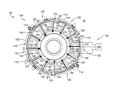
mixture is then ignited for generating hot combustion gases. The combustion
gases are
channeled to the turbine(s) which extracts energy from the combustion gases
for
powering the compressor(s), as well as producing useful work to propel an
aircraft in
flight or to power a load, such as an electrical generator.
[0004] During engine operation, significant heat is produced which raises the
temperature of the frames that surround various engine components.
Specifically, at least
one known frame includes radial support struts which project across an annular
flowpath
to interconnect the inner and outer frame members. Since the temperature of
the motive
fluid flowing through the flowpath changes very rapidly during transient
engine
operation, substantial thermal stresses can be created in the rigid frame
assemblies when
the struts are allowed to heat up and cool down at rates differing
substantially from those
of the inner and outer frame members. This is particularly true with respect
to the turbine
1
CA 02950714 2016-12-06
281145
frame assembly since the exhaust gases which surround the turbine frame
assembly are
subject to the most rapid and greatest changes in operating temperatures and
resulting
thermal stresses. At least some known cooling systems use compressor air or
bore air to
purge and cooling the frame to reduce the thermal gradients. However, the use
of
compressor air or bore flow may result in less efficient engine cycle.
BRIEF DESCRIPTION
[0005] In one aspect, a turbine frame cooling system for use with a gas
turbine engine
is provided. The turbine frame cooling system includes an outer ring defining
a cavity
and a hub positioned radially inward of the outer ring. The turbine frame
cooling system
also includes a plurality of circumferentially-spaced first fairings coupled
between the
outer ring and the hub and a plurality of circumferentially-spaced second
fairings coupled
between the outer ring and the hub, wherein the first and second fairings are
alternatingly
positioned about the hub. The turbine frame cooling system also includes a
plurality of
circumferentially-spaced air scoops coupled to the outer ring. The plurality
of air scoops
extend into a bypass stream and are configured to channel a bypass air cooling
flow into
the cavity of the outer ring.
[0006] In another aspect, a method of cooling a turbine frame of a gas turbine
engine is
provided. The method includes channeling a cooling flow from a bypass duct
through a
plurality of air scoops, wherein the plurality of air scoops are coupled to an
outer ring of a
frame and extend into the bypass duct. The method also includes channeling a
first
portion of the cooling flow through a plurality of first fairings that are
coupled between
the outer ring and an inner hub, and channeling a second portion of the
cooling flow
through a plurality of second fairings that are coupled between the outer ring
and the
inner hub. The plurality of first fairings are alternatingly positioned with
the plurality of
second fairings.
BRIEF DESCRIPTION OF THE DRAWINGS
[0007] FIG. 1 is a schematic illustration of an exemplary gas turbine engine.
2
CA 02950714 2016-12-06
281145
[0008] FIG. 2 is a front cross-sectional illustration of the gas turbine
engine at location
2-2 shown in FIG. 1 illustrating an exemplary turbine frame cooling system.
[0009] FIG. 3 is side cross-sectional view of the gas turbine engine
illustrating the
turbine frame cooling system.
DETAILED DESCRIPTION
[0010] Reference will now be made in detail to present embodiments of the
disclosure,
one or more examples of which are illustrated in the accompanying drawings.
The
detailed description uses numerical and letter designations to refer to
features in the
drawings. Like or similar designations in the drawings and description have
been used to
refer to like or similar parts of the disclosure.
[0011] The exemplary assemblies and methods described herein overcome at least
some disadvantages of known systems and methods for cooling turbine frames in
a gas
turbine engine. Moreover, the systems and methods described herein include an
outer
ring defining a cavity and a hub positioned radially inward of the outer ring.
The turbine
frame cooling system also includes a plurality of circumferentially-spaced
first fairings
coupled between the outer ring and the hub and a plurality of
circumferentially-spaced
second fairings coupled between the outer ring and the hub, wherein the first
and second
fairings are alternatingly positioned about the hub. The turbine frame cooling
system
also includes a plurality of circumferentially-spaced air scoops coupled to
the outer ring.
The plurality of air scoops extend into a bypass stream and are configured to
channel a
bypass air cooling flow into the cavity of the outer ring.
[0012] A first portion of the cooling airflow is channeled radially inward
through the
first fairing along fluid lines housed therein. The metal walls of the fluid
lines are cooled
by the first portion and the temperature of the fluid lines is maintained to
be lower than
the coking temperature of the fluid therein. A second portion of the cooling
airflow
passes over the first fairing and travels circumferentially to heat the outer
ring while
3
CA 02950714 2016-12-06
281145
simultaneously cooling the second fairing and strut housed therein to reduce
the thermal
gradient between the strut and the outer ring and, therefore, reduce the
thermal stresses.
[0013] The use of bypass air simplifies the exterior and interior design of
the engine
and does not require any external pipes to move air from the compressor to the
frame. By
using bypass air, the hub design of the frame is simplified by not requiring
features to
meter the flow of air from inside the engine to the frame. The overall design
is lighter and
simpler than typical historic designs. Additionally, bypass air is typically
cooler than
convention air sources, such as the compressor, such that it cools more
efficiently and
also increased the operating efficiency of the engine by eliminating the need
to capture
compressor air from the primary flowpath.
[0014] The singular forms "a", "an", and "the" include plural references
unless the
context clearly dictates otherwise.
[0015] Approximating language, as used herein throughout the specification and
claims, may be applied to modify any quantitative representation that could
permissibly
vary without resulting in a change in the basic function to which it is
related.
Accordingly, a value modified by a term or terms, such as "about",
"approximately", and
"substantially", are not to be limited to the precise value specified. In at
least some
instances, the approximating language may correspond to the precision of an
instrument
for measuring the value. Here and throughout the specification and claims,
range
limitations may be combined and/or interchanged; such ranges are identified
and include
all the sub-ranges contained therein unless context or language indicates
otherwise.
[0016] As used herein, the terms "first", "second", and "third" may be used
interchangeably to distinguish one component from another and are not intended
to
signify location or importance of the individual components.
[0017] As used herein, the terms "axial" and "axially" refer to directions and
orientations that extends substantially parallel to a centerline of the
turbine engine. The
term "forward" used in conjunction with "axial" or "axially" refers to moving
in a
4
CA 02950714 2016-12-06
281145
direction toward the engine inlet, or a component being relatively closer to
the engine
inlet as compared to another component. The term "aft" used in conjunction
with "axial"
or "axially" refers to moving in a direction toward the engine nozzle, or a
component
being relatively closer to the engine nozzle as compared to another component.
Moreover, the terms "radial" and "radially" refer to directions and
orientations that
extends substantially perpendicular to the centerline of the turbine engine.
[0018] FIG. 1 is a schematic illustration of an exemplary gas turbine engine
assembly
having a longitudinal axis 11. Gas turbine engine assembly 10 includes a fan
assembly 12, and a core gas turbine engine 13. Core gas turbine engine 13
includes a
high pressure compressor 14, a combustor 16, and a high pressure turbine 18.
In the
exemplary embodiment, gas turbine engine assembly 10 may also include a low
pressure
turbine 20. Fan assembly 12 includes an array of fan blades 24 extending
radially
outward from a rotor disk 26. Engine 10 has an intake side 28 and an exhaust
side 30.
Gas turbine engine assembly 10 also includes a plurality of bearing assemblies
(not
shown in Figure 1) that are utilized to provide rotational and axial support
to fan
assembly 12, compressor 14, high pressure turbine 18 and low pressure turbine
20, for
example. To maintain the various components of engine 10 in their proper
relative
operating positions, various engine frame assemblies are provided for rigidly
interconnecting the stationary components and for providing bearing supports
for rotating
components. More specifically, engine 10 includes a turbine frame 46
supporting an aft
bearing 21.
[0019] In operation, air flows through fan assembly 12 and is split by an
airflow splitter
44 into a first portion 50 and a second portion 52. First portion 50 of the
airflow is
channeled through compressor 14 wherein the airflow is further compressed and
delivered to combustor 16. Hot products of combustion (not shown in Figure 1)
from
combustor 16 are utilized to drive turbines 18 and 20 and thus produce engine
thrust. Gas
turbine engine assembly 10 also includes a bypass duct 40 that is utilized to
bypass a
second portion 52 of the airflow discharged from fan assembly 12 around core
gas
5
CA 02950714 2016-12-06
281145
turbine engine 13. More specifically, bypass duct 40 extends between an inner
wall 43 of
a fan casing or shroud 42 and an outer wall 45 of splitter 44.
[0020] FIG. 2 is a front cross-sectional illustration of gas turbine engine 10
at location
2-2 shown in FIG. 1 illustrating an exemplary turbine frame cooling system 100
for
cooling turbine frame 46. FIG. 3 is side cross-sectional view of gas turbine
engine 10
illustrating a portion of turbine frame cooling system 100. In the exemplary
embodiment,
turbine frame cooling system 100 includes an outer ring 102, an inner hub 104,
a plurality
of circumferentially-spaced first fairings 106, and a plurality of
circumferentially-spaced
second fairings 108. Each fairing 106 and 108 is coupled between inner hub 104
and
outer ring 102. Furthermore, fairings 106 and 108 circumferentially alternate
about the
circumference of hub 104 such that each first fairing 106 is positioned
between two
adjacent second fairings 108.
[0021] In the exemplary embodiment, turbine frame cooling system 100 also
includes a
plurality of fluid service lines 110 and a plurality of support struts 112,
both extending
between inner hub 104 and outer ring 102. More specifically, fluid lines 110
extend
through each first fairing 106 and facilitate channeling cooling or
lubricating fluid
between inner hub 104 and outer ring 102. Additionally, each second fairing
108 houses
a strut 112 therein, which provides structural support to outer ring 102. In
the exemplary
embodiment, fairings 106 and 108 extend radially through a primary flowpath
114 (as
shown in FIG. 3) and are exposed to high temperature combustion gases flowing
axially
through engine 10 during engine operation. As such, each fairing 106 and 108
is aligned
with a direction of the combustion gases along flowpath 114 to minimize
aerodynamic
drag pressure losses and flowpath blockage. Furthermore, each fairing 106 and
108 is
formed as a thin-sectioned, symmetrical or non-symmetrical, cambered or non-
cambered
airfoil surrounding either fluid lines 110 or supper strut 12. Alternatively,
fairings 106
and 108 are oriented in any direction and include any shape that facilitates
operation of
turbine frame cooling system 100 as described herein.
6
CA 02950714 2016-12-06
281145
[0022] As described above, struts 112 are exposed to large and frequent
thermal
gradient over various engine 10 operating temperatures. As such, substantial
thermal
stresses may be created in frame 46 if struts 112 are allowed to heat up and
cool down at
rates differing substantially from those of inner hub 106 and outer ring 102.
Additionally, fluid lines 110 are generally formed from metal and absorb heat
from the
combustion gases in flowpath 114. Fluid lines 110 transport a fluid that, when
heated
above a certain temperature, may cause coking within fluid lines 110.
Accordingly, in
the exemplary embodiment, turbine frame cooling system 100 channels cooling
air
through fairings 106 and 108 to manage the thermal gradient of struts 112 and
to maintain
the temperature of fluid lines 110 below the coking temperature of the fluid
within.
[0023] In the exemplary embodiment, turbine frame cooling system 100 includes
a
plurality of circumferentially-spaced air scoops 116 that are coupled to outer
ring 102 and
extend in bypass duct 40 from outer ring 102. Scoops 116 capture a portion of
bypass air
52 from bypass stream 40 and channel bypass air 52 into a cavity 118 defined
in outer
ring 102 to act as a cooling airflow 120. Air scoops 116 facilitate channeling
cooling
airflow 120 into cavity 118 to purge and cool each of outer ring 102, fairings
106 and
108, fluid lines 110, struts 112, and inner hub 104. Although FIG. 2 shows six
air scoops
116, outer ring 102 includes any number of air scoops 116 to facilitate
operation of
turbine frame cooling system 100 as described herein.
[0024] In the exemplary embodiment, turbine frame cooling system 100 also
includes a
plurality of independent cooling circuits 100. Each cooling circuit 122
includes one air
scoop 116, one first fairing 106, and one second fairing 108. More
specifically, air scoop
116 is positioned circumferentially upstream of both first and second fairings
106 and
108 in each circuit 122 such that each air scoop 116 is positioned between a
second
fairing 108 of an adjacent circuit 122 and the first fairing 106 in the same
circuit 122 as
air scoop 116. As such, turbine frame cooling system 100 includes the same
number of
each of air scoops 116, first fairings 106, and second fairings 108.
Furthermore, each
cooling circuit 122 includes a seal 124 coupled within cavity 118 of outer
ring 102. Seals
124 act to divide separate adjacent cooling circuits 122 from one another and
to divide
7
CA 02950714 2016-12-06
281145
cavity 118 into a plurality of cavity segments that are associated with a
corresponding
cooling circuit 122. Seals 124 limit the circumferential travel of cooling
airflow 120
within cavity 118 and are positioned at a circumferential downstream end of
each cooling
circuit 122 between air scoop 116 of an adjacent cooling circuit 122 and
second fairing
108 of the same circuit 122 as seal 124.
[0025] Each cooling circuit 122 operates in a substantially similar manner as
every
other cooling circuit 122. As such, only the operation of one cooling circuit
122 is
described in detail herein. In operation, air scoop 116 captures bypass air 52
from bypass
duct 40 and channels the bypass air 52 into cavity 118 of outer ring 102 as
cooling
airflow 120. Airflow 120 travels circumferentially within outer ring 102 and
cools the
portion of outer ring 102 between air scoop 116 and first fairing 106. Because
the
circumferential distance is relatively small, cooling airflow 120 increases
only slightly in
temperature.
[0026] A first portion 126 of cooling airflow 120 is then channeled radially
inward
through first fairing 106 along fluid lines 110 housed therein. The metal
walls of fluid
lines 110 are cooled by first portion 126 and the temperature of fluid lines
110 is
maintained to be lower than the coking temperature of the fluid therein. First
portion 126
is channeled radially inward through first fairing 106 before cooling air 120
can absorb
much heat from flowpath 114 during the circumferential travel through outer
ring 102.
[0027] A second portion 128 of cooling airflow 120 continues circumferentially
about
outer ring 102 absorbing heat from combustion gases within flowpath 114 as it
travels
such that second portion 128 of cooling airflow 120 is at a higher temperature
than first
portion 126. Second portion 128 is then channeled radially inward through
second
fairing 108 to cool second fairing 108 and strut 112 housed therein. As such,
turbine
cooling system 100 facilitates cooling both first fairing 106 and second
fairing 108, but
cools first fairing 106 more than second fairing 108. Any air that does not
get channeled
into second fairing 108 initially will be blocked from further circumferential
travel by
seal 124 and be forced radially inward through second fairing 108 by seal 124.
As such,
8
CA 02950714 2016-12-06
281145
seals 124 allow for a set amount of heat to be absorbed by cooling airflow 120
as it
travels within a corresponding circuit 122.
[0028] As second portion 128 travels circumferentially around outer ring 102,
it gains
heat and locally heats outer ring 102 before traveling radially through second
fairing 108
to cool second fairing 108 and strut 112. Because second fairing 108 and strut
112 are
positioned within primary flowpath 114, they generally operate at a
significantly higher
temperature than outer ring 102. This temperature difference causes the above-
described
large thermal gradients that lead to thermal stresses between outer ring 102
and second
fairing 108. As such, second portion 128 heats outer ring 108 while
simultaneously
cooling second fairing 108 and strut 112 housed therein to reduce the thermal
gradient
between strut 112 and outer ring 102 and inner hub 104 and, therefore, reduce
the thermal
stresses.
[0029] Once first and second portions 126 and 128 are channeled through
respective
first and second fairings 106 and 108, the cooling air 120 from inner hub 104
into
primary flowpath 114 either axially upstream downstream or axially upstream,
or both, of
fairings 106 and 108 as leakage airflow 130.
[0030] In the exemplary embodiment, turbine frame cooling system 100 also
includes a
control system 132 for controlling cooling airflow 120 entry into air scoops
116 of
cooling circuits 122. Control system 132 includes a temperature sensor 134
coupled to
any combination of first fairing 106, second fairing 108, and outer ring 102.
Furthermore, control system 132 includes a valve 136 coupled to each air scoop
116 to
control entry of bypass air 52 into cooling system 100. Sensors 134 and valves
136 are
operatively coupled to a controller 138. Sensors 134 measure the temperature
of first
fairing 106, second fairing 108, or outer ring 102 and relay a signal
representative of the
measured temperature to controller 138. Controller 138 compares the measured
temperature to a stored predetermined temperature and controls operation of
valves 136
based on the comparison. Specifically, if the measured temperature is below
the
predetermined temperature, then cooling of first fairing 106, second fairing
108, and
9
CA 02950714 2016-12-06
281145
outer ring 102 may not be required, and valves 136 are actuated closed.
Similarly, if the
measured temperature is above the predetermined temperature, then cooling of
first
fairing 106, second fairing 108, and outer ring 102 is required, and valves
136 are
actuated open. Although valves 136 are described herein as being coupled to
each air
scoop 116, in other embodiments, valves 136 are coupled to less than all air
scoops 116.
Alternatively, valves 136 are coupled to outer ring 102 circumferentially
downstream of
air scoop 116 in each circuit 122.
[0031] The exemplary assemblies and methods described herein overcome at least
some disadvantages of known systems and methods for cooling turbine frames in
a gas
turbine engine. Moreover, the assemblies and methods described herein include
an outer
ring defining a cavity and a hub positioned radially inward of the outer ring.
The turbine
frame cooling system also includes a plurality of circumferentially-spaced
first fairings
coupled between the outer ring and the hub and a plurality of
circumferentially-spaced
second fairings coupled between the outer ring and the hub, wherein the first
and second
fairings are alternatingly positioned about the hub. The turbine frame cooling
system
also includes a plurality of circumferentially-spaced air scoops coupled to
the outer ring.
The plurality of air scoops extend into a bypass stream and are configured to
channel a
bypass air cooling flow into the cavity of the outer ring.
[0032] A first portion of the cooling airflow is then channeled radially
inward through
the first fairing along fluid lines housed therein. The metal walls of the
fluid lines are
cooled by the first portion and the temperature of the fluid lines is
maintained to be lower
than the coking temperature of the fluid therein. A second portion of the
cooling airflow
passes over the first fairing and travels circumferentially to heat the outer
ring while
simultaneously cooling the second fairing and strut housed therein to reduce
the thermal
gradient between the strut and the outer ring and, therefore, reduce the
thermal stresses.
Accordingly, the turbine frame cooling system channels cooling air through the
fairings
to manage the thermal gradient of the struts and to maintain the temperature
of the fluid
lines below the coking temperature of the fluid within.
CA 02950714 2016-12-06
281145
[0033] The use of bypass air simplifies the exterior and interior design of
the engine
and does not require any external pipes to move air from the compressor to the
frame. By
using bypass air, the hub design of the frame is simplified by not requiring
features to
meter the flow of air from inside the engine to the frame. The overall design
is lighter and
simpler than typical historic designs. Additionally, bypass air is typically
cooler than
convention air sources, such as the compressor, such that it cools more
efficiently and
also increased the operating efficiency of the engine by eliminating the need
to capture
compressor air from the primary flowpath.
[0034] Exemplary embodiments of turbine frame cooling systems are described
above
in detail. The turbine frame cooling system, and methods of operating such
systems and
devices are not limited to the specific embodiments described herein, but
rather,
components of systems and/or steps of the methods may be utilized
independently and
separately from other components and/or steps described herein. For example,
the
cooling system may also be used in combination with other systems requiring
cooling,
such as compressor frames, and are not limited to practice with only the
turbine frames as
described herein.
[0035] Although specific features of various embodiments of the invention may
be
shown in some drawings and not in others, this is for convenience only. In
accordance
with the principles of the invention, any feature of a drawing may be
referenced and/or
claimed in combination with any feature of any other drawing.
[0036] While there have been described herein what are considered to be
preferred and
exemplary embodiments of the present invention, other modifications of these
embodiments falling within the scope of the invention described herein shall
be apparent
to those skilled in the art.
11