Note: Descriptions are shown in the official language in which they were submitted.
MEASURING WHILE DRILLING SYSTEMS, METHOD AND APPARATUS
[0001]
Technical Field
[0002] This application relates to subsurface drilling, specifically, to
acquiring
information from downhole sensors. Embodiments are applicable to drilling
wells for
recovering hydrocarbons.
Background
[0003] Recovering hydrocarbons from subterranean zones typically involves
drilling
wellbores. Wellbores are made using surface-located drilling equipment which
drives a
drill string that eventually extends from the surface equipment to the
formation or
subterranean zone of interest. The drill string can extend thousands of feet
or meters
below the surface. The terminal end of the drill string includes a drill bit
for drilling (or
extending) the wellbore. Drilling fluid, usually in the form of a drilling
"mud", is
.. typically pumped through the drill string. The drilling fluid cools and
lubricates the drill
bit and also carries cuttings back to the surface. Drilling fluid may also be
used to help
control bottom hole pressure to inhibit hydrocarbon influx from the formation
into the
wellbore and potential blow out at surface.
[0004] Bottom hole assembly (BHA) is the name given to the equipment at the
terminal
end of a drill string. In addition to a drill bit, a BHA may comprise elements
such as:
apparatus for steering the direction of the drilling (e.g. a steerable
downhole mud motor or
rotary steerable system); sensors for measuring properties of the surrounding
geological
formations (e.g. sensors for use in well logging); sensors for measuring
downhole
conditions as drilling progresses; one or more systems for telemetry of data
to the surface;
stabilizers; heavy weight drill collars; pulsers; and the like. The BHA is
typically
advanced into the wellbore by a string of metallic tubulars (drill pipe).
- 1 -
Date Recue/Date Received 2023-09-08
[0005] Modem drilling systems may include any of a wide range of
mechanical/electronic
systems in the BHA or at other downhole locations. Such systems may be called
`downhole tools'. A downhole tool may comprise any active mechanical,
electronic,
and/or electromechanical system that operates downhole. A downhole tool may
provide
any of a wide range of functions including, without limitation: data
acquisition; measuring
properties of the surrounding geological formations (e.g. well logging);
measuring
downhole conditions as drilling progresses; controlling downhole equipment;
monitoring
status of downhole equipment; directional drilling applications; measuring
while drilling
(MWD) applications; logging while drilling (LWD) applications; measuring
properties of
downhole fluids; and the like. A downhole system may comprise one or more
systems
for: telemetry of data to the surface; collecting data by way of sensors (e.g.
sensors for use
in well logging) that may include one or more of vibration sensors,
magnetometers,
inclinometers, accelerometers, nuclear particle detectors, electromagnetic
detectors,
acoustic detectors, and others; acquiring images; measuring fluid flow;
determining
directions; emitting signals, particles or fields for detection by other
devices; interfacing to
other downhole equipment; sampling downhole fluids; etc.
[0006] Downhole tools may communicate a wide range of information to the
surface by
telemetry. Telemetry information can be invaluable for efficient drilling
operations. For
example, telemetry information may be used by a drill rig crew to make
decisions about
.. controlling and steering the drill bit to optimize the drilling speed and
trajectory based on
numerous factors, including legal boundaries, locations of existing wells,
formation
properties, hydrocarbon size and location, etc. A crew may make intentional
deviations
from the planned path as necessary based on information gathered from downhole
sensors
and transmitted to the surface by telemetry during the drilling process. The
ability to
obtain and transmit reliable data from downhole locations allows for
relatively more
economical and more efficient drilling operations.
[0007] Many downhole tools do not include telemetry transmitters. Such
downhole tools
may store information for retrieval when the tool is returned to the surface
or for retrieval
by a wireline tool lowered to the location of the downhole tool on a wire. In
addition or in
the alternative, such downhole tools may interface to another system that
includes a
telemetry transmitter to send data to surface equipment.
- 2 -
Date Recue/Date Received 2022-01-07
[0008] A wide variety of downhole tools are provided by a wide range of
manufacturers.
Different downhole tools may make data available in different formats and/or
using
different protocols. This makes it difficult and/or undesirably expensive to
create a
downhole system which uses downhole tools from different manufacturers to
provide
selected functionalities.
[0009] Different telemetry techniques include transmitting information by
generating
vibrations in fluid in the bore hole (e.g. acoustic telemetry or mud pulse
(MP) telemetry)
and transmitting information by way of electromagnetic signals that propagate
at least in
part through the earth (EM telemetry). Other telemetry techniques use
hardwired drill
pipe, fibre optic cable, or drill collar acoustic telemetry to carry data to
the surface.
[0010] A typical arrangement for electromagnetic telemetry uses parts of the
drill string as
an antenna. The drill string may be divided into two conductive sections by
including an
insulating joint or connector (a "gap sub") in the drill string. The gap sub
is typically
placed at the top of a bottom hole assembly such that metallic drill pipe in
the drill string
above the BHA serves as one antenna element and metallic sections in the BHA
serve as
another antenna element. Electromagnetic telemetry signals can then be
transmitted by
applying electrical signals between the two antenna elements. The signals
typically
comprise very low frequency AC signals applied in a manner that codes
information for
transmission to the surface. (Higher frequency signals attenuate faster than
low frequency
signals.) The electromagnetic signals may be detected at the surface, for
example by
measuring electrical potential differences between the drill string or a metal
casing that
extends into the ground and one or more ground rods.
[0011] There remains a need for downhole systems that can readily acquire data
from
other downhole tools.
Summary
[0012] This invention has a number of aspects including methods for
transmitting data in
downhole environments, methods and apparatus for providing data interfaces to
downhole
tools and downhole systems which are operative to transfer data among downhole
tools.
- 3 -
Date Recue/Date Received 2022-01-07
[0013] One example aspect provides a downhole system comprising first, second
and third
downhole tools. The first downhole tool is in data communication with the
third downhole
tool by way of the second downhole tool. The first downhole tool is in data
communication with the second downhole tool by way of a close proximity data
connection and the second downhole tool is in data communication with the
third
downhole tool by way of a short hop wireless data communication link having a
range
greater than that of the close proximity data connection. The first and second
downhole
tools are provided in adjacent sections of a drill string.
[0014] The second downhole tool may, for example, have the form factor of a
sub that is
coupled in line with the drill string or a probe that is within a bore of the
drill string. In
some embodiments the first and second downhole tools each has the form factor
of a sub
coupled in line with the drill string adjacent to one another.
[0015] The close proximity data connection may comprise a data connection
between an
inductive loop or coil in the first downhole tool and an inductive loop or
coil of the second
downhole tool. In other embodiments the close proximity data connection
comprises a
direct wired or optical connection, a short-range wireless connection or the
like.
[0016] In some embodiments the second downhole tool has the form of a sub
comprising
a first coupling at one end and a second coupling at another end and the
second downhole
tool comprises a first data interface adjacent to the first coupling and a
second data
interface adjacent to the second coupling. The second downhole tool may be
operable to
communicate with the first downhole tool by way of the first data interface or
the second
data interface. In some embodiments the second downhole tool is configurable
to
communicate with the first downhole tool by way of the first data interface
and with
another downhole tool by way of the second data interface.
[0017] Where the second downhole tool has the fowl factor of a probe, the
second
downhole tool may be landed in a drill string section that is coupled to the
sub. The drill
string section may be very short (e.g. it may have a length of 3 feet (about 1
meter) or less).
In some embodiments the probe is supported in the bore between first and
second spiders
which are each supported by a corresponding landing in the drill string
section. An axial
position of the probe relative to the drill string section may be adjustable.
In an example
embodiment spacers are provided between one or both of the first and second
spiders and
- 4 -
Date Recue/Date Received 2022-01-07
the corresponding landings, the spacers movable to adjust an axial positioning
of the probe
relative to the sub_ In some embodiments the probe projects axially from the
drill string
section into the sub. In some embodiments at least an end of the probe that
projects into
the sub is movable and is biased toward the sub.
[0018] The short hop wireless data communication link may, for example,
comprise a
transmitter in the second downhole tool connected to apply a voltage across a
first
electrically-insulating gap portion that separates electrically-conductive
parts of the drill
string uphole and downhole from the first gap portion. The third downhole tool
may
comprise a second electrically-insulating gap portion that separates
electrically-conductive
parts of the drill string uphole and downhole from the second gap portion and
the third
downhole tool comprises a short-hop telemetry receiver connected to monitor
voltages
across the second gap portion. The third downhole tool may communicate data
toward the
surface by applying telemetry signals across the second gap portion. In other
embodiments
the short hop wireless data communication link may comprise a radio-frequency
data
communication protocol_
[0019] The second downhole tool may comprise a controller and a tool library.
The
controller is configured to: obtain a signal from the first downhole tool by
way of the close
proximity data connection, process the signal to identify one or more
properties of the
signal, use the one or more properties to look up in the tool library a set of
one or more
communication parameters, and configure the close proximity data connection
according
to the one or more communication parameters. The one or more properties of the
signal
may include a signal frequency. The second downhole tool may optionally be
configured
to receive data from the first downhole tool on the close proximity data
connection and to
pass a subset of the received data to the third downhole tool by way of the
short hop
wireless data communication link.
[0020] In some embodiments the second downhole tool is configured to receive
data from
the first downhole tool on the close proximity data connection and to pass
only a subset of
the received data to the third downhole tool by way of the short hop wireless
data
communication link.
[0021] Further aspects of the invention and features of example embodiments
are
described herein and/or illustrated in the accompanying drawings.
- 5 -
Date Recue/Date Received 2022-01-07
Brief Description of the Drawings
[0022] The accompanying drawings illustrate non-limiting example embodiments
of the
invention.
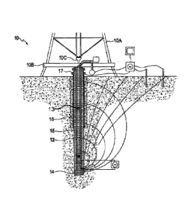
[0023] Figure 1 is a schematic view of a drilling operation.
[0024] Figure 2 is a block diagram of an example downhole system.
[0025] Figure 2A is a block diagram of another example downhole system.
[0026] Figure 3A is a schematic cross section elevation through a section of
drill string
comprising a sub containing electronics coupled to communicate with a tool
contained in a
probe received in a bore of a drillstring.
[0027] Figure 3B and 3C are schematic cross section elevations through a drill
string
containing first and second subs containing electronics and/or sensors
arranged to
communicate with one another.
[0028] Figure 3D is a schematic illustration of a sub configured to
communicate with one
or two adjacent subs. The illustrated sub may provide short-hop or longer-
range telemetry
to communicate data from the one or two adjacent subs to surface equipment
and/or to
other downhole equipment.
[0029] Figure 3E is a schematic illustration of a section of drill string that
includes a sub
containing electronics arranged to communicate with a probe based tool
received within a
bore of the drill string.
[0030] Figure 4 is a block diagram of an example downhole tool.
[0031] Figure 4A is a block diagram of a configuration method for establishing
data
communication (particularly short-range data communication) with a downhole
tool.
[0032] Figure 5 shows a downhole system according to an example embodiment.
- 6 -
Date Recue/Date Received 2022-01-07
Description
[0033] Throughout the following description specific details are set forth in
order to
provide a more thorough understanding to persons skilled in the art. However,
well
known elements may not have been shown or described in detail to avoid
unnecessarily
obscuring the disclosure. The following description of examples of the
technology is not
intended to be exhaustive or to limit the system to the precise forms of any
example
embodiment. Accordingly, the description and drawings are to be regarded in an
illustrative, rather than a restrictive, sense.
[0034] Figure 1 shows schematically an example drilling operation. A drill rig
10 drives a
drill string 12 which includes sections of drill pipe that extend to a drill
bit 14. The
illustrated drill rig 10 includes a derrick 10A, a rig floor 10B and draw
works 10C for
supporting the drill string. Drill bit 14 is larger in diameter than the drill
string above the
drill bit. An annular region 15 surrounding the drill string is typically
filled with drilling
fluid. The drilling fluid is pumped through a bore 13 in the drill string to
the drill bit and
returns to the surface through annular region 15 carrying cuttings from the
drilling
operation. As the well is drilled, a casing 16 may be made in the well bore. A
blow out
preventer 17 is supported at a top end of the casing. The drill rig
illustrated in Figure 1 is
an example only. The methods and apparatus described herein are not specific
to any
particular type of drill rig.
[0035] One aspect of this invention provides a downhole tool comprising a
telemetry
transmitter and, optionally, a range of sensors. The downhole tool is
configured to
communicate with other downhole tools, such as off-the-shelf neutron density,
resistivity,
spectral gamma, oil/water cut meters, or the like. In some embodiments, the
downhole
tool incorporates MWD sensors (e.g. sensors that provide information regarding
the
inclination and/or direction of a portion of the drill string in which the
downhole tool is
located).
[0036] Figure 2 is a block diagram illustrating functional components of an
example tool
20. Tool 20 incorporates or is used together with a sub 21. Tool 20 includes a
telemetry
transmitter 22. In the illustrated embodiment, telemetry transmitter 22 is an
EM telemetry
transmitter (a "gap-based" EM telemetry transmitter) which is coupled across
an
- 7 -
Date Recue/Date Received 2022-01-07
electrically-insulating gap portion 23 provided by a sub 21. Gap portion 23
provides
electrical insulation between an uphole portion of sub 21 and a downhole
portion of sub
21. Tool 20 also includes a controller 24 which, inter alia, controls
telemetry transmitter
22 to send data and a plurality of sensors 26.
10037] In the illustrated embodiment, sensors 26 include an inclination sensor
26A, a
direction sensor 26B, a pressure sensor 26C, a temperature sensor 26D, a shock
and
vibration sensor 26E, and other sensors 26E Other embodiments may have a
different set
of sensors 26. Sensors 26 are coupled to controller 24 such that controller 24
can read
values from sensors 26, and can process those values and/or transmit those
values by way
of telemetry transmitter 22. Some embodiments may not include any sensors 26.
[0038] Coupled to controller 24 is a data interface 28 designed to provide
communication
between controller 24 and another downhole tool. Interface 28 may, for
example,
comprise an inductive loop or coil extending around a bore of sub 20. Figure 2
illustrates
another adjacent tool 30 having a data communication interface 32 connected to
it. Data
communication interface 32 may comprise another inductive loop, for example.
Tool 30
can convey information, for example, sensor readings from sensors in tool 30,
to controller
24 of tool 20 by modulating an electrical current in inductive loop 32 to
encode data
representing the sensor readings. These modulations are picked up by interface
28 which
supplies the encoded data to controller 24. Controller 24 may then store the
encoded data
retrieved from tool 30 and/or transmit the encoded data by way of EM telemetry
transmitter 22 (or another telemetry transmitter such as an MP telemetry
transmitter) either
with or without first processing that data at tool 20.
[0039] Controller 24 may additionally transmit data to tool 30 by way of
interface 32. For
example, controller 24 may receive downlink data, which may include commands
for tool
30 by way of a telemetry receiver 22R. Controller 24 may then pass those
commands or
other data to tool 30 by way of interface 32.
[0040] One issue faced by users who wish to use downhole telemetry tools
together is that
such tools can tend to be quite long. The tools are typically provided in the
form of probes
received within a bore of the drill string. In a typical situation a probe
having telemetry
- 8 -
Date Recue/Date Received 2022-01-07
capability is used to transmit data from a downhole measurement tool that
includes various
sensors. The telemetry probe is typically landed on a landing in an off-the-
shelf drill
collar that is typically made of a non-magnetic material (so as not to
interfere with
magnetic sensors in the measurement tool). The landing is typically at one end
of the
collar (either the uphole or downhole end). There is no standard length for
non-magnetic
drill collars and so, in different jobs, an off-the-shelf telemetry probe may
be landed at
drastically different locations relative to a measurement tool from which it
is expected to
receive data. This can make it difficult to get the induction loop of the
telemetry tool to
line up with an inductive loop of another tool, such as a measurement tool,
within an
acceptable tolerance. It is typical in the prior art to need to adjust the
positioning and/or
overall length of telemetry probes with spacers to achieve the desired
alignment. Even
then significant misalignment of induction loops is common. This can result in
degraded
communication and/or the requirement to use more power to transmit data
signals between
induction loops.
100411 Figure 2A is a block diagram of a system similar to that shown in
Figure 2 except
that tool 20 now communicates with tool 30 by way of a short hop communication
link 29
that includes components 29A and 29B. For one-way communication from tool 30
to tool
component 29B may be a transmitter and component 29A may be a receiver. Some
embodiments provide two-way communication between tools 20 and 30. In such
20 embodiments components 29A and 29B may each comprise a data transceiver
or a system
that includes at least one data transmitter and at least one data receiver.
[0042] Short hop component 29B and communication interface 28 may be combined
in a
separate tool 33. Tool 33 may have its own housing and power supply. One
advantage of
the arrangement of Figure 2A is that it removes constraints on the location of
tools 20 and
30. Each tool may be located in a position desirable for that tool as long as
tools 20 and
are both within the range of communication link 29. Another advantage is that
tool 33
may be designed to facilitate alignment of data interfaces 28 and 32 with one
another.
[0043] In some embodiments, short hop communication link 29 uses
electromagnetic
signals to communicate between components 29A and 29B. In some cases these
signals
30 may have frequencies much higher than those used for EM telemetry
communication to
- 9 -
Date Recue/Date Received 2022-01-07
surface equipment. In an example embodiment, short hop communication link is
provided
using the technology described in PCT publication WO 2015/031973.
[0044] Tool 33 may have various form factors. In some embodiments tool 33 has
the
form of probe that is received within bore 13 of the drill string. In such
embodiments, tool
33 may be used in combination with a sub designed to support tool 33 for
optimum data
communication with tool 30. In some embodiments tool 33 may be in the form of
a drill
string section or 'sub' that forms a part of the drill string. In either case,
especially
because tool 33 needs to provide only limited functionality (tool 33 does not
need to
include any large sensors, for example) tool 33 may be very compact compared
to tool 20
and/or tool 30. In some embodiments, tool 33 is 3 feet (about 1 m) long or
less.
[0045] Figure 3A shows an example embodiment wherein tool 33 has the form of a
probe
33-1 supported in bore 13 by supports 33-2 which may, for example, be in the
form of
spiders (like spoked or apertured disks) that allow fluid to pass tool 33
while firmly
supporting the body of probe 33-1 in bore 13. Supports 33-2 engage
corresponding
landings in a sub 12-1. An end 33-3 of probe 33-1 extends out of the bore of
sub 12-1 into
a bore of tool 30 which, in this embodiment, has the form of a sub 12-2 that
makes up a
part of drill string 12. This arrangement closely aligns data communication
interfaces 28
and 32. Data interfaces can be in the form of inductive coil to coil, a
hardwire connector,
or a physical attachment to the tool 30.
[0046] In the embodiment of Figure 3A, sub 12-1 includes an electrically
insulating
portion (a 'gap') 35 and tool 33 may communicate to tool 20 (which may be
uphole or
downhole from tool 33) by applying voltages across gap 35. Voltage may be
applied, for
example, by way of supports 33-2 which may be electrically conductive and may
land on
opposing sides of gap 35.
[0047] It is sometimes necessary to re-cut the threaded couplings of subs or
other drill-
string sections. A single re-cutting may not adversely affect alignment of
data
communication interfaces 28 and 32 very much. In some embodiments, sub 12-1 is
designed such that data communication interface 28 is initially high relative
to data
communication interface 32 such that an initial re-cutting of the threads of
the couplings
- 10 -
Date Recue/Date Received 2022-01-07
that couple subs 12-1 ad 12-2 will improve the alignment of data communication
interfaces 28 and 32. In some embodiments spacers 33-5 are provided to allow
easy
adjustment of the alignment of communication interfaces 28 and 32. If
alignment is
disturbed by re-cutting of threads coupling subs 12-1 and 12-2 (resulting in
one or both of
these subs being made shorter) then one or more of spacers 33-5 may be moved
from the
landing closest to sub 12-2 to the landing away from sub 12-2. As a further
alternative,
probe 33-1 may be constructed to allow adjustment of the positions of
couplings 33-2
along the body of probe 33-1 (e.g. by means of threaded couplings, spacers,
pins or the
like).
[0048] As a further alternative, a probe may be telescoping or spring loaded
such that an
end of the probe (or the entire probe) is movable relative to the drill
string. The probe may
include a surface that abuts an abutment surface of tool 30 such that the end
of the probe
that supports the interface to tool 30 automatically has a fixed spatial
relationship to the
abutment surface. Through the use of adjustment spacers and/or telescoping
and/or
spring-loaded features an end of the probe may have a fixed attachment to the
top of tool
30. The fixed attachment may provide a pressure-rated connection, or a harsh-
environment
direct electrical connection between tools 33 and 30.
[0049] In another embodiment tool 33 has the form factor of a sub 12-3.
Electronics may
be enclosed in a compartment in a wall of the sub. In this embodiment,
interface 28 may
comprise an inductive loop or coil that is located within or on a wall
defining bore 13
within sub 12-3. For example the loop or coil may be located within an
electronics
module or a removable cartridge located in a compartment in a wall of sub 12-
3_ The
compartment may comprise an annular compartment extending around a bore of sub
12-3,
a pocket in a wall of sub 12-3 or the like. The loop or coil does not
necessarily extend
around a bore of sub 12-3. The loop or coil may have various orientations. In
some
embodiments the loop or coil is oriented such that an axis of the loop or coil
extends
radially relative to sub 12-3. In such embodiments the loop or coil may be
used to
facilitate data communications by way of one or more corresponding loops or
coils in a
probe located within the bore of sub 12-3 or in another nearby downhole tool.
In some
.. embodiments the axis of the loop or coil extends generally parallel to a
longitudinal axis of
sub 12-3.
- 11 -
Date Recue/Date Received 2022-01-07
[0050] A tool 33 having the form factor of a sub may be used to communicate
with tools
30 that have the form factor of a probe or with tools 30 that have the form
factor of a sub,
or both. Figure 3B shows an example embodiment where a tool 33 including its
communication interface 28 is provided in a sub 12-3. In Figure 3B tool 30 is
provided in
a sub 12-2 which is coupled into drill string 12 adjacent to sub 12-3.
[0051] Tool 33 includes an inductive loop 28 and tool 30 includes an inductive
loop 32.
The spacing, D, between inductive loops 28 and 32 is fixed, given by the
distances
between coils 28 and 32 from the couplings at the ends of sub 12-3 and tool
30, and may
be relatively short (e.g. less than 2 feet - about .6 meters). Providing a
relatively small
spacing D between inductive loops 28 and 32 can permit exchange of data
between
inductive loops 28, 32 with much lower power than would be required for more
widely-
spaced inductive loops.
[0052] In Figure 3B, tool 33 is uphole relative to tool 30. Figure 3C is
another example
embodiment in which tool 33 is downhole relative to tool 30_ It can be seen by
comparing
Figures 3B and 3C that inductive loop 28 should be either near the pin end or
near the box
end of sub 12-3 depending on whether sub 12-2 will be coupled to the pin end
or the box
end of sub 12-3.
[0053] In some embodiments, of which Figure 3D is an example, a sub 12-5
containing
tool 33 includes inductive loops 28 near both ends of sub 12-5. Inductive loop
28A near
pin end 12A and inductive loop 28B near box end 12B are shown in Figure 3D. A
controller 34 of tool 33 may select which one of inductive loops 28A and 28B
will be used
to communicate with a tool 30. A sub 12-5 containing a tool 33 as shown in
Figure 3D
may be used in conjunction with a tool 30 that is either uphole from or
downhole from the
sub 12-5. In cases where sub 12-5 is coupled into drill string 12 between two
tools 30
(which may provide different fimctionalities) the controller 34 of tool 33 may
communicate with an uphole one of the tools 30 by way of inductive loop 28A
and the
other one of the tools by way of inductive loop 28B.
[0054] In Figure 3E tool 30 is provided in a probe 37 which is landed in a
drill-string
section 12-4 that is located adjacent to sub 12-3. Tool 33 is provided in sub
12-3 as
- 12 -
Date Recue/Date Received 2022-01-07
described above. Tool 33 includes inductive loop 28. Tool 30 includes an
inductive loop
32 which is located near to inductive loop 28.
[0055] A tool 33 as described herein may be adapted to communicate with any of
a
plurality of tools 30, each of which may communicate using different
frequencies and
protocols. Each of tools 30 may provide different data values. These data
values may be
processed downhole, used as control inputs for downhole processes and/or
transmitted to
surface equipment. As shown in Figure 4, tool 33 may optionally include a tool
library 38.
Tool library 38 cross-references discoverable characteristics of known tools
30 with
communications protocols for tool 33 to use in communicating with those tools
30. Tool
library 38 may also include information identifying the data values available
from each
tool 30. If signals from tool 30 are encrypted, tool library 38 may include a
key for
decrypting the signals.
[0056] Tool library 38 may comprise a data store accessible to controller 34
which
includes a data structure containing the above information.
[0057] Figure 4A is a flow chart illustrating a method that a tool 33 may
perform for
establishing data communication with a tool 30. Block 42 involves obtaining a
signal
from tool 30. This may be done by way of interface 28. Block 42 may involve
passively
listening for a signal and/or sending signals to tool 30 by way of interface
28. In some
embodiments tool 33 sends a sequence of different wake-up signals to tool 30.
The
signals may, for example, differ in frequency, communication protocol and/or
content.
[0058] Block 44 analyzes the signal obtained in block 42. Block 44 may, for
example,
determine one or more of: a frequency or frequencies on which the signal is
transmitted;
method that the signal is encoded (tool 33 may try various ways to decode the
signal and
see which one(s) work and/or may observe characteristics of the signal such as
how the
signal appears to be modulated).
[0059] Block 45 uses the information derived in block 44 to look up the tool
30 in tool
library 38. Assuming that the information from block 44 matches a known tool
30 then
method 40 proceeds to block 46 which retrieves a communication protocol from
tool
- 13 -
Date Recue/Date Received 2022-01-07
library 38. Block 47 configures data communication interface 28 using
information from
tool library 38 to communicate with the known tool 30_
[0060] In optional block 48, tool 33 configures itself to select a subset of
data from tool 30
to transmit_ For example, tool 33 may configure itself to transmit to tool 20
every Nth
value for a first parameter and every Mth value for a second parameter made
available by
tool 30. Here, M and N are integers that may be the same or different. This
capability
may be applied to reduce data traffic uphole from tool 33 and also to reduce
power
requirements of tool 33 by reducing the volume of data to be transmitted.
Information
specifying which data to select for a particular tool 30 may be provided in
tool library 38.
In other embodiments tool 33 is manually configured for use with a particular
tool 30. The
manual configuration may pick from a number of configurations in tool library
38 and/or
may set specific parameters which specify the way that tool 33 handles
obtaining,
processing and/or transmitting data from a tool 30.
[0061] In some embodiments a tool 33 is not provided and tool 30 communicates
directly
with tool 20 as shown in Figure 2. In some such embodiments tool 20 is compact
(particularly in length). In any of the embodiments depicted in Figures 1 to
3E tool 33
may be replaced directly with tool 20. For example, tool 20 may be provided in
the form
of a sub that is coupled into a drill string immediately adjacent to a tool 30
or is arranged
to communicate with a tool 30 that has the form factor of a probe located
within bore 13 of
the drill string. The probe may pass through the bore of the sub in some
embodiments.
An example of this construction is illustrated in Figure 3E (with tool 33
replaced by tool
20).
[0062] As another example, a sub containing tool 20 (or tool 33) may be
coupled directly
to the end of a sub containing tool 30 at any location within the drill
string, thereby
automatically placing inductive loop 28 of tool 20 a distance D from inductive
loop 32 of
tool 30.
[0063] In some embodiments a tool 33 provides functionality in addition to
that which is
discussed above. For example, a tool 33 may include one or more sensors. Tool
33 may
transmit outputs from the one or more signals to tool 20 or to other downhole
tools.
- 14 -
Date Recue/Date Received 2022-01-07
[0064] Figure 3E illustrates a section of drill string 12 which includes a sub
20 as
described above (i.e. with tool 33 replaced by sub 20) and a probe suspended
in a bore 13
of the drill string. Probe 30 has an inductive loop 32 which, when probe 30 is
installed in
the bore of the drill string, generally aligns (e.g. aligns within +/- 3 feet
(about 1 meter))
.. with a corresponding inductive loop 28 of sub 20_
[0065] In some embodiments a tool 20 may have reduced or minimal
functionality. For
example, a tool 20 may serve primarily to receive data from tool 33 and to
transmit the
received data directly or indirectly to surface equipment using EM telemetry
or some other
telemetry modality.
[0066] It is not mandatory that data interfaces 28, 32 be provided by
inductive loops or
coils_ In addition or in the alternative a telemetry sub as described herein
may include a
data interface that provides a direct wired or optical connection or an
alternative short-
range wireless data connection, such as gap to gap electromagnetic telemetry
(as
described, for example, in PCT publication W02015/031973), or an acoustical
data
connection between the telemetry sub and a downhole tool located in the drill
string in
close proximity to the telemetry sub. For example, alternative short-range
wireless
connections may include other forms of electromagnetic data communication such
as
BluetoothTM, WiFi, or a custom designed wireless transmitter that operates at
an
electromagnetic communication frequency in the range of 100Hz to 1GHz or the
like. In
some such embodiments, data interfaces 28, 32 are provided by commercially-
available
wireless communication devices such as single-chip wireless LAN transceiver
chips.
Such chips are available from suppliers such as Texas Instruments', AtmelTm
and
Broadcomm". In some embodiments, wireless communication is provided according
to
an IEEE 802.11 standard such as 802.11n or 802.11 b/g.
[0067] In various embodiments described herein where sub 20 includes both a
gap-based
EM telemetry transmitter and an interface (e.g. 28) that facilitates data
communication
with another downhole tool, sub 20 may receive data from the other downhole
tool by way
of interface 28 and then re-transmit the data by way of the gap-based EM
telemetry
transmitter. The data may be received directly at surface equipment or passed
to the
- 15 -
Date Recue/Date Received 2022-01-07
surface equipment by one or more intermediate nodes that receive and then re-
transmit the
data.
[0068] Use of such equipment can occur according to a method involving
generating data
at a downhole tool (such as data from a rotary steerable tool, gamma sensor, a
resistivity
sensor, directional sensors, or the like) and transmitting the data using a
short-range coil-
based telemetry system (by, for example, modulating electrical current in a
loop or coil
according to the data to be transmitted). The data is received at a
corresponding coil or
loop in apparatus as described herein and then retransmitted using a gap-based
EM
telemetry system. Retransmitting the data may involve decoding the data and
then re-
encoding the data. The retransmitted data may be received at surface equipment
or
received at a node farther up the drill string from where it can again be
retransmitted using
gap-based EM telemetry, mud pulse telemetry or another suitable telemetry
modality.
[0069] Some embodiments provide a drill string comprising a sub comprising a
gap-based
EM telemetry transmitter and a short-range telemetry receiver that may, for
example,
comprise a coil or loop. The sub is located in the drill string immediately
adjacent to a
tool configured to generate data and transmit the data by modulating
electrical current in a
loop or coil to yield a short range telemetry signal that is received at the
sub. The drill
string optionally includes a node configured to receive data transmitted by
the gap-based
EM telemetry transmitter and to retransmit the received data. In some
embodiments the
node comprises a plurality of telemetry transmitters and is configured to
retrancmit the
received data using one or more of the plurality of telemetry transmitters. In
some
embodiments the node comprises an electrically insulating gap in the drill
string and is
configured to receive the data transmitted by the gap-based EM telemetry
transmitter by
monitoring a potential difference across the gap. The node may be separated
from the sub
by a plurality of drill string sections in some embodiments.
[0070] Figure 5 shows an example downhole system 50 according to an example
embodiment. Downhole system 50 comprises a first downhole tool 52, a second
downhole
tool 54 and a third downhole tool 56. In this embodiment, third downhole tool
56 has two-
way communication with surface equipment. Second downhole tool 54 optionally
has the
capacity to receive downlink telemetry transmissions originating at surface
equipment.
- 16 -
Date Recue/Date Received 2022-01-07
First downhole tool 52 relies on the second downhole tool 54 to receive or
send data. First
and second downhole tools 52, 54 are in data communication by way of a close
proximity
data connection 55. This data connection may operate over a very short range.
Second
downhole tool 54 and third downhole tool 56 are in data connection with one
another by
way of a short hop data connection 57. First downhole tool 52 may, for
example, comprise
a rotary steering system (RSS).
[0071] While a number of exemplary aspects and embodiments have been discussed
above, those of skill in the art will recognize certain modifications,
permutations, additions
and sub-combinations thereof. It is therefore intended that the following
appended claims
and claims hereafter introduced are interpreted to include all such
modifications,
permutations, additions and sub-combinations as are within their true spirit
and scope.
Interpretation of Terms
[0072] Unless the context clearly requires otherwise, throughout the
description and the
claims:
= "comprise," "comprising," and the like are to be construed in an inclusive
sense, as
opposed to an exclusive or exhaustive sense; that is to say, in the sense of
"including, but not limited to".
= "connected," "coupled," or any variant thereof, means any connection or
coupling,
either direct or indirect, between two or more elements; the coupling or
connection
between the elements can be physical, logical, or a combination thereof.
= "herein," "above," "below," and words of similar import, when used to
describe
this specification shall refer to this specification as a whole and not to any
particular portions of this specification.
= "or," in reference to a list of two or more items, covers all of the
following
interpretations of the word: any of the items in the list, all of the items in
the list,
and any combination of the items in the list.
= the singular forms "a," "an," and "the" also include the meaning of any
appropriate
plural forms.
[0073] Words that indicate directions such as "vertical," "transverse,"
"horizontal,"
"upward," "downward," "forward," "backward," "inward," "outward," "left,"
"right,"
- 17 -
Date Recue/Date Received 2022-01-07
"front," "back," "top," "bottom," "below," "above," "under," and the like,
used in this
description and any accompanying claims (where present) depend on the specific
orientation of the apparatus described and illustrated. The subject matter
described herein
may assume various alternative orientations. Accordingly, these directional
terms are not
strictly defined and should not be interpreted narrowly.
[0074] Where a component (e.g. a circuit, module, assembly, device, drill
string
component, drill rig system, etc.) is referred to above, unless otherwise
indicated,
reference to that component (including a reference to a "means") should be
interpreted as
including as equivalents of that component any component which performs the
function of
.. the described component (i.e., that is functionally equivalent), including
components
which are not structurally equivalent to the disclosed structure which
performs the
function in the illustrated exemplary embodiments of the invention.
[0075] Specific examples of systems, methods and apparatus have been described
herein
for purposes of illustration. These are only examples. The technology provided
herein
can be applied to systems other than the example systems described above. Many
alterations, modifications, additions, omissions and permutations are possible
within the
practice of this invention. This invention includes variations on described
embodiments
that would be apparent to the skilled addressee, including variations obtained
by: replacing
features, elements and/or acts with equivalent features, elements and/or acts;
mixing and
.. matching of features, elements and/or acts from different embodiments;
combining
features, elements and/or acts from embodiments as described herein with
features,
elements and/or acts of other technology; and/or omitting combining features,
elements
and/or acts from described embodiments.
[00761 It is therefore intended that the following appended claims and claims
hereafter
.. introduced are interpreted to include all such modifications, permutations,
additions,
omissions and sub-combinations as may reasonably be inferred. The scope of the
claims
should not be limited by the preferred embodiments set forth in the examples,
but should
be given the broadest interpretation consistent with the description as a
whole.
- 18 -
Date Recue/Date Received 2022-01-07