Note: Descriptions are shown in the official language in which they were submitted.
CA 02951326 2016-12-06
WO 2015/185181
PCT/EP2015/00976
1
DISPENSING DEVICE WITH CONTROL BODY IN ORDER TO AXIALLY MOVE A
DISPENSING ELEMENT
The invention relates to a dispensing device, the receiving space of which
contains a dispensable medium, which can be extracted by means of a
dispensing element of the device for an extraction process, and having a
control body, which moves a connecting body, guided in a longitudinally
displaceable manner in a housing part, from an inactive initial position to
an active extraction position, by means of a rotary motion, wherein a
media-carrying connection is created between the receiving space and the
dispensing element, wherein at least one control part of the control body
can be brought into abutment with at least one control path of the
connecting body.
Dispensing devices of this type are used for technical, cosmetic,
pharmaceutical and medical purposes, in particular in conjunction with
injections as a means for administering medication. The dispensing
devices are intended to allow the operator to safely and conveniently
perform the measures to be taken for the application of the container
media, allowing, for instance in the case of disposable syringes, the
delivery device to be used by the patient himself. As prior art, WO
2012/113008 discloses a dispensing device of the type initially referred to,
in the form of a syringe head for an injection syringe, wherein a protective
cover for the injection needle forming the dispensing orifice is provided as
a control body to be operated for an extraction process. By means of a
rotary movement of the protective cover, a connecting body bearing the
injection needle is axially movable in a housing part, which can be coupled
to an injection cylinder in such a way that the connecting body establishes
a media connection with the container, here the interior of the injection
cylinder. In order to convert the rotary movement of the protective cover
into the axial movement of the connecting body, in the known solution a
drive part, which is connected in rotation to the protective cover and is
CA 02951326 2016-12-06
WO 2015/185181
PCT/EP2015/00976
2
referred to in the document as a "pinion", has circumferential, radially
projecting guide knobs, which are arranged in the housing part that is
mounted on the container, in this case on the injection cylinder. Depending
on the inclination of the slotted-guide tracks, the rotational movement
transmitted by coupler lamellae from the protective cover to the pinion
causes the longitudinal displacement of the pinion and through this the
opening movement of the connecting body.
The known solution is unsatisfactory in several respects. On the one hand,
the design of the coupling connection between the protective cover and
the pinion entails a corresponding structural complexity. On the other
hand, the reliability of the function leaves a lot to be desired, as, for the
typically used polymer materials with limited stiffness, the entry of the
guide knob into the slotted-guide tracks and the guidance inside the latter
are not proof against jamming.
In addition, the pinion has to fit tightly over the cannula during
manufacture, which can easily result in damage to the needle tip and/or
the silicone layer on the needle. This can directly affect the user, as such
damage can easily lead to painful injections.
Based on this state of the art, the invention addresses the problem of
providing a dispensing device of the type mentioned at the outset, which is
characterized by an improved functional reliability in a simple design.
According to the invention, this problem is solved by a dispensing device
having the features of claim 1 in its entirety.
According to the characterizing part of claim 1, an essential feature of the
invention is that during the rotary movement of the control body, the ,
respective control part follows the rotary movement relative to the housing
part in an axially unchanged manner and, via the respective control path of
the connecting body, which has a slope, moves the former from the initial
position to the extraction position. Because the arrangement is such that
CA 02951326 2016-12-06
WO 2015/185181
PCT/EP2015/00976
3
the control part does not execute an axial movement during the rotary
actuation, no clutch device is required to permit an axial movement
between the control element and the control part upon transmission of the
actuating torque. The device according to the invention can be realized in
a particularly fail-safe manner using a simplified design based on
conventional plastic materials, such as polyolefins.
In particularly advantageous exemplary embodiments, the control body
has two control parts which are diametrically opposite in relation to the
longitudinal axis of the device, which are, in the initial position of the
connecting body, rotatable from a lower vertex position formed by the
respective control paths of the connecting body in the direction of an upper
vertex position of the respective control paths, which are arranged above
the lower vertex position in the initial position of the connecting body in
axial direction, relative to the longitudinal axis. Unlike WO 2012/113008, in
which the axial displacement of the connecting body tightly enclosing the
cannula is transmitted to the connecting body via an axially movable
pinion, the connecting body can be directly actuated via the axially
immobile control parts of the control body, which are supported by the
control paths of the connecting body and which upon rotary movement
move away from the lower vertex position of the guide paths and thereby
effect the axial displacement of the connecting body in a particularly
secure manner.
In a particularly advantageous manner, the respective control path can
encompass, at least partially, in a hollow ring-like and co-axial manner, a
connecting channel, which is located in the connecting body and
constitutes the media connection to the container, wherein a functional
body specifically designed for the particular container application is
arranged on the connecting body. In this case, the functional body can, for
instance in the case of an injection, have a cannula, in the case of a
transfer into another receptacle, the closure of which has to be punctured,
have a hollow mandrel, in the case of a dropper application, have a
dropper, in the case of ointment or gel application, have an ointment
CA 02951326 2016-12-06
WO 2015/185181
PCT/EP2015/00976
4
applicator, in the case of an as yet unknown application, have a
connecting element, for example a conical connection.
Functional bodies and connecting bodies can be separate components,
which may, for instance, be interlockable. This has the advantage of using
similar connecting bodies for different functional bodies. Alternatively,
connecting bodies and functional bodies can also be integral with each
other, i.e. no sealing is required between the connecting channel and the
functional body.
The control body can be designed in the manner of a protective cover for
the respective functional bodies, supporting on its inside the control part in
the form of at least one inwardly projecting lug part, which is formed at
least partly convex in the direction of the connecting body when the
protective cover is on.
For particularly advantageous exemplary embodiments, the protective
cover can, in the direction of its open free end having at least one
protruding annular segment, reach under an assignable annular segment
of the housing part in the inactive initial position of the protective cover
at
this housing part, such that after a rotation of the protective cover around a
predetermined distance, until the connecting body has reached its active
extraction position, the paired annular segments, which are disengaged
from one another, and the protective cover, can be removed from the
housing part. Whereas, in the case of the aforementioned WO
2012/113008, in which the protective cover is merely secured by way of a
predetermined breaking point on the housing part, there is the risk of the
operator removing the protective cover after partial rotational actuation by
detachment of the predetermined breaking point and thus no effective
extraction process can be carried out; this risk is eliminated in the
invention because the protective cover can only be removed when the
active extraction position has been reached.
With particular advantage, the connecting body is provided with at least
CA 02951326 2016-12-06
WO 2015/185181
PCT/EP2015/00976
one longitudinal guide, guided longitudinally movably in the housing part
and secured against all rotational movement.
Depending on the application purpose of the device, the respective
containers can be molded to the housing part and/or subsequently be
connected to the housing part as an independent component. In a
particularly advantageous manner, for a dispensing device allocated to a
container, which is produced in a blow-molding process, such as the
known bottelpacke process and filled in the mold, the container can be
connected to the housing part in the blow mold.
The subject matter of the invention is also a carrier unit for a functional
body which is provided, in particular, for a dispensing device according to
one of claims 1 to 9 and which has the features of claim 10 in its entirety.
As a further subject matter the invention provides a container system
having the features of claim 11 and consisting of an outer closed sheath,
the sheath parts of which can be separated from each other along at least
one separation point, to expose a dispensing device, which is designed in
particular according to one of claims 1 to 9, or a carrier unit, which is
designed in particular according to claim 10.
Below the invention is explained in detail, using exemplary embodiments
shown in the drawing. In the drawings:
Figs. 1 and 2 show a front view and a plan view, respectively, of a
filled
plastic container, which can be compressed in the manner of a
bellows for an extraction process, which can be carried out by
means of an extraction device according to the invention;
Fig. 3 shows a perspective oblique view of the container of
Figs. 1
and 2 in connection with an exemplary embodiment of the
extraction device according to the invention;
Fig. 4 shows the components of an exemplary embodiment of the
extraction device according to the invention in an exploded
CA 02951326 2016-12-06
WO 2015/185181
PCT/EP2015/00976
6
perspective view;
Fig. 5 shows a perspective view of the exemplary embodiment
of the
dispensing device, partly cut-away and partly translucent;
Fig. 6 shows a perspective view of the protective cover of
the
exemplary embodiment in longitudinal section;
Figs. 7 and 8 show cut-away perspective views of the exemplary
embodiment, the extraction device being shown in the initial
position (Fig. 7) and the extraction position (Fig. 8);
Fig. 9 shows an enlarged perspective view of the connecting
body of
the exemplary embodiment shown in a perspective oblique
view;
Fig. 10 shows the connecting body of Fig. 9 in a
longitudinally cut-
away perspective view;
Fig. 11 shows a perspective oblique view of the separately
illustrated
housing part of the exemplary embodiment;
Fig. 12 shows the housing part of Fig. 11 in a longitudinally
cut-away
perspective view;
Fig. 13 shows a longitudinal section of a modified exemplary
embodiment of the dispensing device, provided with an outer
sheath surrounding the protective cover;
Fig. 14 shows a front view of the exemplary embodiment of Fig.
13
with the sheath removed;
Fig. 15 shows a front view, partially cut away, of the
exemplary
embodiment of Figs. 13 and 14, the extraction position being
shown with the protective cover removed;
Figs. 16 and 17 show longitudinal sections of two further exemplary
embodiments of the dispensing device;
Fig. 18 shows a front view, partially cut away, of the
exemplary
embodiment of Fig. 17, the extraction position being shown
with the protective cover removed;
Fig. 19 shows a longitudinal section of a further exemplary
embodiment having an outer sheath attached thereon;
Fig. 20 shows a front view of the exemplary embodiment of Fig.
19
CA 02951326 2016-12-06
WO 2015/185181
PCT/EP2015/00976
7
with the outer sheath removed;
Fig. 21 shows a partially cut-away front view of the exemplary
embodiment of Figs. 19 and 20, shown in the extraction
position;
Fig. 22 shows a longitudinal section of a further modified
exemplary
embodiment having an outer sheath;
Fig. 23 shows a front view of the exemplary embodiment of Fig.
22
without the outer sheath;
Fig. 24 shows a partially cut-away front view of the exemplary
embodiment of Figs. 22 and 23, the extraction position being
shown without the protective cover;
Figs. 25 and 26 show a front view and a top view of an exemplary embodiment
of the container system according to the invention, comprising
a container, a dispensing device and an outer sheath;
Fig. 27 shows a perspective oblique view of the container
system and
Fig. 28 shows a perspective view of the container system of
Figs. 25
to 27 in a larger scale and in a cut-away perspective view.
With reference to the drawings, the invention is explained by means of
examples, in which the dispensing device for the extraction of liquid or
semi-solid filling material from a plastic container is provided, as it can,
in
the manner of an ampoule, for instance, according to the bottelpack
method, be manufactured and filled in a blow mold. Figs. 1 and 2 show, in
a separate view, a corresponding container 1 having a container body 3,
which is designed and compressible in the manner of a flat bellows, so
that it can be used for carrying out an application process, e.g. an injection
process. The container 1 in the illustrated examples designed for a filling
volume of 1 to 2 ml transitions from the container body 3 via a collar part 5
into a neck part 7. If such a container 1 is provided for use in connection
with an extraction device according to the invention, the extraction device
is attached to the neck part 7 by a housing part 9, see Fig. 3.
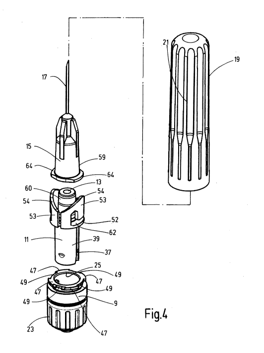
Fig. 4 shows the components of a first exemplary embodiment of the
extraction device according to the invention having a connecting body 11
CA 02951326 2016-12-06
WO 2015/185181
PCT/EP2015/00976
8
guided such that it can move longitudinally in the housing part 9. It has an
inner, axial connection channel 13 for a fluid-conducting connection to the
contents of the container 1 during the extraction process. A functional
body 15 adjoins the upper, in Fig. 4, end of the connecting body 11, which
continues the inner channel 13 of the connecting body 11 to a functional
part forming the dispensing element, in the present example, an injection
needle 17. The upper termination of the device is formed by a protective
cover 19, which in the mounted position, see Figs. 5, 7 and 8, reaches
over the functional body 15 and the connecting body 11, and the open rim
region of which is locked to the housing part 9, as will be explained in
more detail below. The protective cover 19 forms a control body, which
can be used to transfer the device from the initial position into an active
extraction position. This happens by means of a rotary movement of the
protective cover 19, which is provided with an external longitudinal
corrugation 21 for good traction.
Further details of the construction of the housing part 9 and the
connecting body 11 can be seen most clearly in Figs. 9 to 12. The
housing part 9 has, on the whole, the shape of a hollow cylinder having a
coaxial inner cavity 25, which is closed at the end 27 located at the
bottom in Figs. 11 and 12. If the extraction device, as in the case of the
present exemplary embodiment, is provided for the extraction of filling
material from a container 1, which is produced in a blow molding process
and is filled in the mold, the complete assembly shown in Fig. 5 can be
inserted into the former as an insert before the final closure of the blow
mold. When the head jaws of the mold are closed, the plastic hose
forming the neck part 7 of the container 1 is then molded to the outside of
the housing part 9, as can be seen in Fig. 13. The closed end 27 of the
housing part 9 thus forms the container closure. A circumferential ribbing
23 on the housing part 9, which is shown as a longitudinal ribbing in Fig. 4
and a horizontal ribbing in Figs. 11 and 12, forms a kind of gearing for a
fixation based on a positive-locking engagement during the shaping of the
neck part 7.
CA 02951326 2016-12-06
WO 2015/185181
PCT/EP2015/00976
9
From the closed end 27, a truncated cone 29, open at the end, extends
coaxially into the cavity 25. Close to its opening, the truncated cone 29 is
closed by a membrane 31, forming the perforation region, which is
pierced in the extraction process, see Figs. 7 and 8, by a hollow mandrel
33 which, as shown most clearly in Fig. 10, forms the lower end of the
connecting channel 13 in the connecting body 11. The connecting body
11 is displaceable in the cavity 25 of the housing part 9 for moving it from
the initial position (Fig. 7) into the extraction position (Fig. 8), in which
the
mandrel 33 has pierced the membrane 31, longitudinal ribs 35 on the
housing part 9 forming a longitudinal guide in conjunction with longitudinal
grooves 37 in the cylinder jacket 39 of the connecting body 11. For an
engagement of the connecting part 11 in the initial position and in the
axial positions corresponding to the extraction position, upper latching
notches 41 and lower latching notches 43 are formed at respectively
diametrically opposed locations on the cylinder jacket 39 of the
connecting body 11, for engagement with latching lugs 45 on the inside of
the cavity 25 of the housing part 9 in the initial position or in the
extraction
position.
As mentioned before, the protective cover 19 is locked on the housing
part 9 at the rotational position corresponding to the initial position. For
this purpose, it has annular segments 47 at the open end, between which
gaps 49 are located. As complementary locking elements, projecting
annular segments 51 are formed at the open end of the protective cover
19, which reach under the annular segments 47 on the housing part 9 at
the rotational position corresponding to the initial position, as shown in
Fig.
5. When the protective cover 19 is rotated into the rotational position
corresponding to the extraction position, annular segments 51 in the
region of the gaps 49 are removed from the engagement with the annular
segments 47 and the protective cover 19 can be removed. In that way, a
bayonet-type interlock is formed.
As can best seen in Figs. 9 and 10, the connecting body 11 has a radially
protruding flange part 52 at the upper end of its cylinder jacket 39, the
CA 02951326 2016-12-06
WO 2015/185181
PCT/EP2015/00976
wall parts 53 of which, forming parts of a circular cylinder, extend
coaxially. The free upper rim of the wall parts 53 forms control paths 54,
which extend between the lower vertex position 55 and the upper vertex
position 56. To generate the longitudinal displacement of the connecting
body 11 from the initial position into the extraction position, the protective
cover 19 has two control parts, which are diametrically opposite in relation
to the longitudinal axis of the device. As can best be seen in Figs. 5 and 6,
they have the shape of lugs that are rounded at their ends 57, which are
arranged in the interior of the protective cover 19 at the transition to a
radially expanded cylinder section 58 of the protective cover 19, the
former being arranged on the outside of the wall parts 53 of the
connecting body 11. Figs. 5 and 7 show the rotational position of the initial
position, in which the ends of the lugs 57 are located at the lower vertex
position 55 of the control paths 54. If the protective covers 19 are rotated
by 90 in one or the other direction of rotation, the lugs 57 move towards
the upper vertex position 56 of the control paths 54, generating the axial
displacement of the connecting body 11 and thus the movement of the
mandrel 33 piercing through the membrane 31, at unchanged axial
positions of the protective cover 19 and the housing part 9. For a pierced
membrane 31 (Fig. 8), the part of the connecting body 11 surrounding the
channel 13 and forming the mandrel 33, extends into the truncated cone
29 with an end cone 63, the end rim 65 of which is in contact with the end
cone 63 as a sealing lip. If the protective cover 19 reaches the position
rotated by 90 and if the extraction position is reached, the annular
segments 51 of the protective cover 19 come into alignment with the gaps
49 on the housing part 9 and then the protective cover 19 can be
removed, and the injection needle 17 is released for an application
procedure.
As can be seen most clearly in Fig. 4, the functional body 15 as carrier of
the injection needle has a initial body 59 which, as can be seen most
clearly from Figs. 7 and 8, reaches over a pin part 60, which at the
connecting body 11 surrounds the end section of the connecting channel
13. The fluid connection from the connecting channel 13 to the needle 17
CA 02951326 2016-12-06
WO 2015/185181
PCT/EP2015/00976
11
continues in the interior of the initial body 59. The functional body 15 has,
for attachment to the connecting body 11, radially projecting flange parts
64 from the lower edge region, which in the installed state adjoin the
planar upper side 62 of the flange parts 52 of the connecting body 11 and
are held thereon by wall parts 61, which are formed on cutouts of the wall
parts 53 of the connecting body 11. By means of the functional body 15
thus fixed to the extraction device, the protective cover 19 can be
removed in the extraction position, and an extraction process can be
carried out by executing an application of filling material by means of the
injection needle 17 by compressing the bellows-like container body 3 of
the container 1. The same applies to the application of drops, e.g. for oral,
nasal, ophthalmic, topical, etc. treatments, as well as the application of
semi-solid products such as ointments, creams or gels, using suitable,
applicators known per se.
Figs. 13 to 15 show a modified exemplary embodiment in which the
protective cover 19 is enclosed by an outer sheath 71. This can be
formed during the production of the container 1 by blow molding from the
plastic hose adjoining the neck part 7, which is extruded into the blow
mold, when the mold head jaws are closed, wherein a predetermined
breaking point 66 (Fig. 13) can be formed at the place of attachment to
the neck part 7, where the sheath 71 can be detached together with the
protective cover 19. As a further difference to the previous exemplary
embodiment, the connecting body 11 does not have a mandrel 33 made
of plastic molded onto the main body 59, but a hollow needle 67, which is
shown in the initial position in Fig. 13 and in the extraction position after
piercing the membrane 31 in Fig. 15. In this embodiment, the part of the
connecting body 11 is eliminated, which in the previously described
exemplary embodiment forms the end cone 63 having the adjoining
mandrel 33 at the end of the connecting channel 13, as the hollow needle
67 itself forms the seal on the pierced membrane 31.
In a preferred case (not shown), the needle 17 and the hollow needle 67
may be formed integrally, as a double-pointed injection needle, resulting
CA 02951326 2016-12-06
WO 2015/185181
PCT/EP2015/00976
12
in a small, unusable dead volume.
Fig. 16 shows an exemplary embodiment in which, as in the example of
Figs. 13 to 15, a hollow needle 67 is provided on the base body 59 of the
functional body 15 instead of a plastic mandrel 33 molded to the
connecting part 11. In the example of Fig. 16, however, the container 1 is
not molded with its neck part 7 to the outside of the housing part 9. On the
contrary, the container 1 has a closed neck part 7, to which the housing
part 9 is tightly connected, e.g. glued, locked or welded. As shown in Fig.
16, a sealing layer 69 made of an elastomer rests on the planar upper
end wall 68. In the extraction position, the hollow needle 67 penetrates
the elastomer material and the wall 68 of the neck part 7.
The further exemplary embodiment shown in Figs. 17 and 18 differs from
the example of Fig. 16 only in that the housing part 9 has a sleeve-like
extension 70, which is used to snap the housing part 9 onto the outside of
the neck part 7 of the container 1. Again, the neck part 7 is closed by a
planar wall 68, to which a sealing layer 69 of elastomer is attached. Fig.
18 shows the extraction state having a pierced sealing layer 69 and
pierced wall 68.
In the further exemplary embodiment of Figs. 19 to 21, the neck part 7 of
the container 1 is again molded onto the outer side of the housing part 9,
as in the examples of Figs. 1 to 15. Also, a plastic mandrel 33 is formed
onto the connecting body 11 for piercing the diaphragm 31 of the housing
part 9. Instead of an injection needle 17 forming the dispensing element,
a hollow application pin 72 is mounted to the base body 59 of the
functional body 15. By means of such a mandrel 72, for instance, an
elastomer closure of an injection bottle or an infusion bag can be pierced.
As a further difference to the first-described embodiment of the housing
part 9 in the example of Figs. 19 to 21, the latter has a hollow end cone
73 extending along the inside of the collar part 5 into the inside of the
container body 3 at the end facing the container 1. Furthermore, as in the
example of Figs. 13 to 15, an outer sheath 71 surrounding the protective
CA 02951326 2016-12-06
WO 2015/185181
PCT/EP2015/00976
13
cover 19 is detachably molded over a predetermined breaking point 66.
The further modified exemplary embodiment of Figs. 22 to 24
corresponds to the exemplary embodiment of Figs. 19 to 21, with the
difference that no functional body 15 continuing the connection channel
13 is attached to the connecting body 11. Rather, the end-side pin part 60
of the connecting body 11 is designed as a connection part, for instance
in the form of a conical connection 74 or for the formation of an
interlockable conical connection part. As provided in the examples of Figs.
13 and 19, an outer sheath 71 is provided for the protective cover 19, the
former can be removed together with the protective cover 19 after the
predetermined breaking point 66 has been released. Particularly
advantageous is a substance-to-substance, positive-locking and/or form-
locked connection of protective cover 19 and outer sheath 71.
Figs. 25 to 28 show an exemplary embodiment in which the dispensing
device forms a completely encapsulated container system. In this regard,
several casing parts are provided, which extend from the container body 3
of the container 1 to the upper end 76 allocated to the dispensing element.
In this case, a first casing part 77 is provided, which conjunctively
surrounds, starting at the upper end 76, the inner protective cover 19 with
a central part 78 having the form of an externally concave, curved tubular
body and which has laterally projecting wing parts 79 arranged
diametrically opposite to each other as handle parts. The wing parts 79
have a convexly curved end rim 80. This casing part 77 is detachably
connected to a second casing part 82, which surrounds the housing part 9,
via a predetermined break point 81. Wing-shaped grip flaps 83, which are
aligned with the wing parts 79 of the first casing part 77, extend
diametrically outwards from the second casing part 82. Stay bars 84
extend from the grip straps 83 to the outside of the container body 3.
The casing part 77 is connected to the outer longitudinal corrugation 21 of
the protective cover 19. In this way, by releasing the predetermined
breaking point by rotating into any direction of rotation, the rotary
CA 02951326 2016-12-06
WO 2015/185181
PCT/EP2015/00976
14
movement of the protective cover 19 is simultaneously initiated to move
the device into the extraction position, where the protective cover 19 can
be removed. The first casing part 77 can be conveniently separated by
means of the wing parts 79 serving as handles. When the device is in the
extraction position, i.e. after removal of the casing part 77 together with
the protective cover 19, the device can be conveniently handled for the
respective intended application processes by means of the lateral grip
straps 83 remaining in connection with the container body 3. In the case
of the bracing formed by the bars 84, the functional body 15 can be safely
used, for instance, for injection purposes, without the premature
compression of the container body 3 occurring, because the actuating
force for activating the dispensing device is not applied via the container 3
but via the grip straps 83.
The internal structure of the device, not shown in Figs. 25 to 27, can
essentially correspond to the exemplary embodiment described first, as
illustrated by way of example in Fig. 28. It goes without saying that
variations of averted device parts can be present within the encapsulation
formed by the cover parts 77, 82, which, for instance, correspond to the
exemplary embodiments according to Figs. 13 to 24.