Note: Descriptions are shown in the official language in which they were submitted.
CA 02951485 2016-12-07
WO 2016/007688 PCT/US2015/039642
ELECTRIC WATER HEATER SYSTEMS
FOR POWER GRIDS WITH DISTRIBUTED GENERATION
TECHNICAL FIELD
The claimed invention relates to a technology with a contribution to
greenhouse gas
emissions mitigation, and more particularly to water heater control systems
for thermal storage
of excess power from distributed-generation sources.
BACKGROUND
Conventionally, power distribution involved producing power at one or more
power
plants, then routing that power through a system of power cables, to
inverters, to loads such as
residential homes. Traditionally, distribution from the power plants to the
loads includes several
highly regulated steps whereby the voltage is sequentially reduced until it
enters the residence at
a predetermined, standard voltage. Furthermore, power is distributed with a
predetermined,
standard alternating current (AC) frequency.
Increasingly, power is supplied to power grids from distributed generation
(DG) sources.
Such DG sources include photovoltaics, solar-thermal systems, wind, biomass,
and geothermal
power sources, among others. DG sources provide a voltage boost to the grid
wherever they are
connected. In small quantities, DG sources can reduce the power required of a
base load
generator such as a power plant. As such, DG is seen as a mechanism for
achieving reduced
greenhouse gas emissions, and, if implemented properly, a mechanism for
reducing load on the
electrical grids on which they are deployed.
Conventional power grids are often ill equipped to deal with the
ramifications, however,
of DG power generation. In areas where DG sources exceed a certain threshold,
the power
generated by DG sources, either alone or in combination with power provided by
a base plant,
can exceed the demand for power amongst the loads on that portion of the grid.
This can cause
so-called "upstream" current flow, away from the DG sources and loads and
towards the power
plant. Conventional power grids can be damaged by this type of current flow,
and often this
scenario results in either overvoltage at the area of the grid having DG
sources, or disconnection
of the DG sources and loads from the grid entirely. The inability of
conventional power grids to
handle DG in excess of the power draw by nearby loads has caused some areas to
throttle the
implementation of renewable technologies where the DG sources combined exceed
the minimum
power usage in that area.
1
CA 02951485 2016-12-07
WO 2016/007688 PCMJS2015/039642
Furthermore, because conventional power grids rely on single (or few) sources
to provide
power to the grid, managing the frequency of the AC current provided is
relatively simple.
Conventional grids provide power at a predetermined frequency, and need only
contend with the
effects that connected loads may have on the signal shape. For these reasons,
electronics that
draw power from an electrical grid are often required to comply with standards
to reduce
unwanted effects on the shape of the signal on the power grid, such as
harmonics. With the
introduction of hundreds or thousands of DG sources, the shape of the power
signal can be
modified not just by resistive loads, but also by power sources. DG sources
that provide power
out of phase or do not provide clean sine wave voltages, can degrade the
signal of the power
supply. The inability of conventional power grids to maintain a clean,
sinusoidal power supply
with larger contributions from DG sources has caused some areas to throttle
implementation of
renewable technologies where the DG sources combined exceed a set percentage,
for example
15%, of maximum power usage in that area.
It would be desirable to provide systems and methods that could address these
issues for
a power grid having DG sources.
SUMMARY OF THE INVENTION
An energy storage system for use on a power grid having DG sources includes a
water
heater tank, an upper heating package, a lower heating package, and a
controller. The tank has a
lower portion and an upper portion. The upper heating package includes an
upper thermostat
configured to sense an upper portion temperature and an upper resistive
heating element
configured to heat the upper portion. Likewise, the lower heating package
includes a lower
thermostat configured to sense a lower portion temperature, and a lower
resistive heating
element configured to heat the lower portion. The controller is coupled to a
power line having a
voltage. The controller is configured to:
(a) provide power to the upper resistive heating element when the upper
portion
temperature is below a first predefined temperature;
(b) provide power to the lower resistive heating element when the voltage
exceeds a
standard voltage and the lower portion temperature is below a second
predefined temperature,
and the conditions of (a) are not met;
(c) provide power to the lower resistive heating element when the voltage is
less than the
standard voltage and the lower portion temperature is below a third predefined
temperature, and
the conditions of (a) are not met; and
2
CA 02951485 2016-12-07
WO 2016/007688 PCT/US2015/039642
(d) turn off power to both the lower and upper resistive heating elements when
none of
the conditions (a)¨(c) are met.
The above summary of the invention is not intended to describe each
illustrated
embodiment or every implementation of the present invention. The detailed
description and
claims that follow more particularly exemplify these embodiments.
BRIEF DESCRIPTION OF THE DRAWINGS
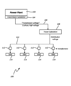
Fig. 1 is a schematic illustration of a simple power distribution system,
according to an
embodiment.
Fig. 2 is a simplified perspective view of a water heating system according to
an
embodiment.
Fig. 3 is a wiring diagram of a water heater according to an embodiment.
Fig. 4 is a flowchart depicting a method of operating a water heater according
to an
embodiment.
Fig. 5 is a schematic of a network of distributed generation sources, loads,
and water
heaters, according to an embodiment.
While the invention is amenable to various modifications and alternative
forms, specifics
thereof have been shown by way of example in the drawings and will be
described in detail. It
should be understood, however, that the intention is not to limit the
invention to the particular
embodiments described. On the contrary, the intention is to cover all
modifications, equivalents,
and alternatives falling within the spirit and scope of the invention as
defined by the appended
claims and their equivalents.
The invention may be embodied in other specific forms without departing from
the
essential attributes thereof; therefore, the illustrated embodiments should be
considered in all
respects as illustrative and not restrictive.
DETAILED DESCRIPTION OF THE DRAWINGS
According to various embodiments, a hot water heater is operable in such a way
that
excess power from a power grid is absorbed in the form of thermal energy,
preventing
disconnection of a distribution network from the broader grid. In some
embodimen and ts, the
distribution network comprises one or more distributed generation (DG)
sources. By absorbing
the excess energy from the grid during peak DG production periods, renewable
energy sources
can be used more efficiently, without damaging equipment or appliances. Such
energy
absorption, and its later release, provides benefits to users of the grid as
well as the utility.
3
CA 02951485 2016-12-07
WO 2016/007688 PCT/US2015/039642
Applications and methods for managing the use of such water heaters, as well
as allocating the
benefits therefrom, are also disclosed, according to further embodiments.
Fig. 1 is a schematic illustration of power distribution system 100, according
to an
embodiment. Power distribution system 100 includes power plant 102,
transmission substation
104, transmission lines 106, power substation 108, distribution bus 110,
transformers 112, and
loads 114.
Power plant 102 can be any power generator, such as a coal plant, natural gas
plant,
hydroelectric plant, nuclear plant, or any other type of power plant. The
system shown in Fig. 1
is simplified, in that power distribution system 100 only includes one power
plant 102. In
complex power distribution grids, multiple power plants 102 may be used. For
example, in
modern complex distribution grids, there may be "base load" plants 102 which
generate a
constant quantity of power at relatively low cost per Watt-hour (Wh), and
various supplemental
power plants 102 that are used during periods with increased power usage.
Power plant 102 is arranged adjacent to transmission substation 104 in the
schematic of
Fig. 1. Transmission stations 104 regulate the output of power plants 102,
providing a high-
voltage, three-phase output that is suitable for transmission across long
distances to remote loads.
Transmission lines 106 route power from transmission substations 104. Often,
the
majority of the distance between power plant 102 and the desired final
location for power
produced therefrom is crossed via transmission lines 106. Transmission lines
106 are configured
to carry three-phase power (often via four power lines: one for each of the
three phases, and one
for ground) at very high voltage.
Power substations 108 receive power from transmission lines 106, and reduce
the voltage
to a distribution voltage. Often the distribution voltage is a few thousand
volts. The power at
distribution voltage can then be distributed across distribution bus 110.
Transformers 112 reduce the voltage even further, to a standard voltage that
is usually
determined by the country in which the power distribution system 100 is
located. For example,
in the United States the peaks of the distribution voltage should be
approximately 170V (with a
root-mean-square voltage of 120V).
Loads 114 could be any of a variety of loads, such that the impedance of each
load 114
can be different from one another and can vary with time. Some loads 114 can
be purely
resistive, others can introduce feedback (such as harmonics or other effects
that degrade the
sinusoidal nature of the supplied power). Loads 114 can be residential,
governmental, or
commercial. One example of a load 114 is a house, which draws power from
distribution bus
110 to run electrical appliances such as air conditioning, lighting, and
electronics.
4
CA 02951485 2016-12-07
WO 2016/007688 PCT/US2015/039642
Conventionally, loads 114 all have positive impedance; that is, each of loads
114 draws
power from distribution bus 110. With the introduction of DG sources, loads
114 may in fact
provide more energy back to distribution bus 110 than they consume. Many
transformers 112
allow power to flow back from loads 114 into distribution bus 110, where it
can be used by other
loads 114. If a sufficiently large quantity of DG sources are generating
power, and the power
output from those DG sources onto distribution bus 110 exceeds the draw of
power from
distribution bus 110, then power will continue to flow opposite to the
conventional power
distribution direction. This so-called "upstream" power flow, through power
substations 108 and
even to transmission substations 104, can be damaging to equipment that was
not designed to
accommodate upstream flow.
Some line inverters and substations of conventional systems do not allow
upstream flow
at all, or restrict it. In those situations, the voltage on distribution bus
110 will exceed the
predefined distribution voltage. As such, transformers 112 provide a
proportionally high voltage
to loads 114. These high voltages can be dangerous, and can damage electronics
present at loads
114. Often, to prevent damage or injury resulting from these high voltages, a
utility responds to
over voltage conditions by disconnecting the area of the grid.
According to one embodiment, loads 114 include water heaters configured to
draw power
from distribution bus 110 when the voltage on distribution bus 110 exceeds a
certain limit. In
some embodiments, these water heaters are configured to continue to draw power
from
distribution bus 110 until either the water contained therein reaches a
maximum, or until the
voltage on distribution bus 110 returns to a normal level. Such systems
effectively increase the
impedance of loads 114 to absorb excess DG power, and prevent damage to or
disconnection of
power distribution system 100.
Fig. 2 is a simplified perspective view of a water heating system 200,
according to an
embodiment. According to the embodiment shown in Fig. 2, a tank 202 is coupled
to a water
line via cold water input 204, and provides hot water via hot water output
206. Water heating
system 200 includes lower heating package 208L and upper heating package 208U.
Each of the
water heating packages 208L and 208U are connected to power line 210 via
controller 212.
Power line 210 is connected to a distribution grid (e.g., distribution bus 110
of Fig. 1), via an
intervening transformer (e.g., transformer 112 of Fig. 1). It should be
understood that water
heating system 200 of Fig. 2 has been simplified for clarity. For example,
tank 202 may contain
safety pressure relief systems or water draining systems that are not directly
impacted by the
systems described herein, and as such have been omitted.
CA 02951485 2016-12-07
WO 2016/007688 PCT/US2015/039642
To aid in description of water heating system 200, directional labels such as
"top" and
"bottom" or -upper" and "lower" arc used. It should be understood that these
labels are with
reference to a gravitational reference frame. As shown in Fig. 2, the "top" is
at the top of the
page and the "bottom" is at the bottom of the page. These directions are
useful in describing the
function of a traditional water heater, wherein stored hot water rises while
stored cold water falls,
with respect to gravity. In other embodiments, other reference frames may be
used, and the
reference frame described herein should not be construed to limit the
invention, as there are other
orientations and reference frames that are usable to accomplish the same or
similar results.
Like conventional water heater tanks, tank 202 is configured to hold a certain
quantity of
hot water (often 20-100 gallons) ready for use in a residential setting. In
operation, the water
contained by tank 202 is thermally stratified; that is, the water at the top
of tank 202 will be at a
relatively higher temperature (indicated as temperature Ti), while the water
at the bottom of tank
202 will be at a relatively lower temperature (indicated as temperature T2).
Cold water is introduced at cold water input 204, which is attached to a water
source
(such as a municipal water line or a well) to provide a supply of cold water.
To promote the
thermal stratification of the water held by tank 202, cold water input 204
routes this cold water to
the bottom of tank 202. As shown in Fig. 2, cold water input 204 is a dip
tube. Similarly, hot
water output 206 promotes the thermal stratification of tank 202 by removing
hot water from a
location near the top of tank 202. Typically, as hot water output 206 draws
water from tank 202,
a substantially equivalent quantity of cold water is introduced at the bottom
of tank 202 by cold
water input 204.
In some embodiments, as cold water is introduced at the bottom of the tank the
bottom
thermostat will call for heat and energize the bottom element (assuming that
the top element is
not heating). While the bottom thermostat and element do most of the water
heating work, the
top thermostat and element can be used to respond to an extended hot water
draw. The top
thermostat and element thus provide for fast recovery.
Lower heating package 208L and upper heating package 208U include resistive
heaters
in the embodiment shown in Fig. 2, configured to heat water in tank 202, as
well as thermostats.
Lower heating package 208L and upper heating package 208U typically will not
operate their
resistive heaters at the same time, to prevent overloading the circuit from
which water heating
system 200 draws power. Rather, upper heating package 208U is configured to
heat the water
stored in the upper portion of tank 202 until the temperature Ti in that
region reaches a preset
value. Once temperature Ti reaches that preset value, lower heating package
208L is configured
6
WO 2016/007688 PCT/US2015/039642
to heat the water stored in the lower portion of tank 202 until the
temperature T2 in that region
reaches a second preset value, often lower than the preset value for
temperature Ti.
Power line 210 provides power to operate lower heating package 208L and upper
heating package 208U. Power line 210 is connected to a distribution bus (e.g.,
distribution
bus 110 of Fig. 1). In some embodiments, a simple step-down transformer (e.g.,
transformer
112 of Fig. 1) is located in between power line 210 and the distribution bus.
Thus, when DG
sources combine to raise the voltage present on the distribution bus, the
voltage on power line
210 rises proportionally.
Controller 212 alters the target temperatures to be reached based on the
voltage at
power line 210. Controller 212 senses the voltage on power line 210, and
allocates power to
each of the heating packages 208L and 208U accordingly. In doing so,
controller 212
causes increased power draw when power line 210 is above its standard voltage,
storing the
energy derived therefrom as thermal energy in tank 202. Later, water heating
system 200
need not draw as much power from the distribution bus, because the water
contained
therein will have been preheated.
Controller 212 comprises a means for communicating with both upper heating
package 208U and lower heating package 208L. In the embodiment shown in Fig.
2, this is a
wired communications means. In alternative embodiments, however, the means for
communicating with two or more heating packages can be wired or wireless. For
example, a
wired means could include a signal wire that instructs either of the heating
packages 208U
and/or 208L whether to operate or cease operating. In other embodiments, the
means for
wired communication could be a power cable that is either powered or unpowered
based on
whether the heating packages 208U and/or 208L should run. In other
embodiments, controller
212 can provide a wireless signal, such as via WIFI, Bluetooth , or another
signal that
propagates wirelessly, to instruct the heating packages 208U and/or 208L that
they should run
or not run. In embodiments, power need not be routed to the heating packages
208U and/or
208L through controller 212.
By powering the heating packages 208U and 208L as directed by the controller
212,
the draw of power from the distribution bus can be spread out to make improved
use of DG
sources, and prevent disconnection of the distribution bus from the wider
power grid as a
result of overvoltage. Particular methods for operating the heating packages
208U and 208L
can be implemented by the controller 212. The means for carrying out these
methods can be
incorporated into the controller 212 as, for example, software (e.g., a
processor that is
designed to run a particular routine for operating the heating packages 208U
and 208L based
on received inputs) or hardware (e.g., bimetal theimometers, liquid expansion
theimometers,
or other sensors
7
6819270
Date Recue/Date Received 2021-08-17
CA 02951485 2016-12-07
WO 2016/007688 PCT/US2015/039642
and/or actuators that correspond to specific temperatures at locations within
the tank 202, for
example). One specific method by which controller 212 can be operated is
described with respect
to Fig. 4, for example.
Fig. 3 is a wiring diagram of a water heating system 300, according to an
embodiment.
Water heating system 300 includes lower heating package 308L, upper heating
package 308U,
power line 310, and controller 312. Lower heating package 308L includes lower
resistive load
314L and lower thermostat 316L. Similarly, upper heating package 308U includes
upper
resistive load 314U and upper thermostat 316U. Similar elements to those
described previously
with respect to Fig. 2 are recognizable by similar numbering, in that those
elements are iterated
by 100. For example, lower heating package 208L of Fig. 2 is substantially
similar to lower
heating package 308L of Fig. 3, and so on.
Each of the heating packages 308L and 308U are shown in more detail, and
include both
a resistive load (314L, 314U) and a thermostat (316L, 316U). The resistive
loads (314L, 314U)
can be used to convert electrical energy into thermal energy, dissipating heat
into the adjacent
water. As such, resistive loads 314L and 314U can be, for example, simple
resistors.
Thermostats 316L and 316U gauge temperature in the lower and upper portions of
the water
heater system (e.g., 12 and Ti of Fig. 2). Thermostats 316L and 316U could be,
for example,
thermocouples, therm i stors, resistance thermometers, or some other device
for measuring
temperature.
Each of the heating packages 308L and 308U receive power via leads (indicated
as red,
black, blue, and yellow) that connect them to power line 310 via controller
312. Controller 312
is configured to distribute power to each of the heating packages 308L and
308U based on the
temperature measured at each of the thermostats 316L and 316U, as well as the
voltage at power
line 310. Controller 312 can allocate power amongst lower and upper heating
packages 308L
and 308U to maintain appropriate water temperature and/or store electrical
energy from power
lines 310 during specific time periods.
3Controller 312 can also be configured to interact with a wired or wireless
network. For
example, controller 312 can include a processor and an antenna or bus
configured to route data
about the operation of the system to a mobile device, a server, or the
utility.
Fig. 4 is a flowchart depicting a method 400 of operating a water heater
according to an
embodiment.
The method begins at start block 402.
At block 404, the temperature Ti in the upper portion of the water heater
(see, e.g., the
embodiment shown in Fig. 2) is measured. The standard electric water heater
uses two elements,
8
CA 02951485 2016-12-07
WO 2016/007688 PCT/US2015/039642
each controlled by a thermostat. Power is supplied to a factory set high limit
attached to the
upper thermostat. If the upper thermostat is calling for heat (i.e., if Ti is
less than a minimum
predetermined temperature), it connects power to the upper heating element, as
shown at block
406. In some embodiments, the upper thermostat and element heat the top 25% to
30% of the
water, while the remainder of the water is heated by the lower thermostat and
element. Once the
upper thermostat condition of block 404 switches to "No," power can be sent to
the lower
heating element. Water heaters work in this non-simultaneous fashion so that
the load never
exceeds the maximum of the associated circuit breaker and wires.
At block 408, line voltage is measured. Renewable generation in a given area
can exceed
the load in that area, driving up the line voltage. If the voltage gets too
high, the renewable
generation will trip off line. As such, according to some embodiments, the
line voltage is
measured and load attached to the grid to absorb renewable energy while
maintaining the
customer supply of needed hot water.
At block 410, the line voltage is compared to a standard line voltage. For
example, in
some locations standard line voltage is 120V AC. If those locations, if the
line voltage
monitored in block 408 exceeds 120V AC, the line voltage exceeds the standard.
In other
locations, different standard voltages can be used, depending on the typical
line voltage in that
region.
The purpose of the comparison described at block 410 is to ascertain those
time periods
where an excess of DG-based power is affecting the power grid. The comparison
between line
voltage and the standard line voltage determines the behavior of the lower
heater, such that the
lower heater is more likely to run when line voltage exceeds the standard, as
described in more
detail with respect to the remaining blocks of the flow chart. In some
embodiments, it may be
desirable to require some additional voltage offset, such that the lower
heater is not likely to be
activated to absorb excess energy unless there is truly a glut of DG-supplied
power. For
example, in the embodiment described above, the standard compared to the line
voltage could be
set at 121V, 122V, 125V, or any other voltage selected to reduce the
likelihood of a "false
positive" of excess DG-based power. Additionally, in some embodiments,
utilities can actively
control DG-generated power by either directly or indirectly adjusting the
voltages that control
the system. In some embodiments, the utility can remotely modify the voltage
set-point that
indicates that excess renewable energy is available.
If the line voltage is greater than the standard (or the standard plus some
offset) as
described at block 410, then the system considers whether the lower
temperature T2 is less than a
predetermined maximum at block 412. The maximum temperature at block 412 is in
place for
9
CA 02951485 2016-12-07
WO 2016/007688 PCT/US2015/039642
safety and to prevent damage to the heater system. The maximum temperature
depends on many
factors, including the hot water temperature set point that the user of the
hot water sets. In some
embodiments, mixing valves on the hot water delivery side can allow the tank
to be driven to
higher temperatures in order to absorb more renewable energy.
If the temperature is less than the predetermined maximum at block 412, then
the lower
heater is operated at block 414. As the lower heater is run (block 414), the
upper temperature Ti
is compared to its minimum value at block 404, the line voltage is again
monitored at block 408,
and the temperature compared to a predetermined maximum at block 412, as
previously
described.
In the event that the temperature T2 exceeds its predetermined maximum at
block 412
while the line voltage still exceeds the standard set point at block 410, the
lower heater will be
shut off at block 416. This prevents a variety of undesirable effects, such as
scalding water
provided by the water heater system or damage to components of the water
heater caused by
excessive heat. The lower heater will remain off until the lower temperature
T2 falls.
The lower heater can still run even if the line voltage does not exceed the
standard
voltage at block 410. In the event that the line voltage does not exceed the
standard, the water
heater operates in a similar fashion to conventional water heaters, starting
at block 418. The
bottom thermostat and element run when the lower temperature T2 is below a
minimum
temperature. The minimum temperature is often far less than the set point for
the upper
temperature TI, as described with respect to block 404. The minimum
temperature is set to
preheat water and ensure that hot water can be provided during a sustained
water draw.
At block 420, if the lower temperature T2 is below the minimum, the lower
heater will be
operated at block 414. If the temperature T2 in the lower portion of the water
heater exceeds the
minimum at block 418, neither upper nor lower heaters are operated, at block
416.
The flowchart above describes an improved system for operation of an electric
water
heater. Rather than a simple on/off switch with a temperature setting, the
thermostats of the
water heater can control the lower heating element at two different set
points. The lower set
point is used when the voltage on the line is normal. This lower set point
warms the water to
ensure there is sufficient hot water in the event of a large draw, and that
the upper element will
be able to supply the amount of hot water required. If the line voltage
exceeds some preset level,
then a higher set point is used. In this way the water heater can absorb some
of the excess
renewable energy.
In alternative control methods, the system can be modified to include other
features. For
example, in some embodiments, sanitization cycles can be performed. Legionella
is a group of
CA 02951485 2016-12-07
WO 2016/007688 PCT/US2015/039642
bacterial that is common in soil and aquatic systems including water heaters.
Often, water
heaters are operated at temperatures that coincide with good growing
conditions for Legionella.
As such, in some embodiments the water heater control system may designed to
periodically
bring the entire tank temperature to a kill point for Legionella or other
bacteria. For example, the
system could be configured to reach 122 F once per week for one hour.
Additionally or alternatively, the system could incorporate a reporting
function, whereby
the control system periodically reports operational conditions including water
temperatures, line
voltage, and more complex data such as power absorbed or renewable energy
stored, to the
residential user of the water heater, the utility, and/or any other party.
This functionality could
be enabled via a Wi-Fi connection to the water heater control system, which
can allow the utility
to change the voltage levels at block 410, and could allow the utility to call
or prevent a
renewable charge based on factors other than voltage. It could also let the
utility know how
much load they have available (i.e., how many heaters in the area of the
electrical grid are
capable of absorbing additional renewable energy). This dispatchability can be
particularly
useful when dealing with wind generation. An App could let the customer
monitor and control
the usage of their water heater much the same way they can use a programmable
thermostat to
set their cooling and heating systems.
Fig. 5 is a schematic of a network 500 of distributed generation sources,
loads, and water
heaters, according to an embodiment. As shown in Fig. 5, a distribution bus
510 carries
electrical power throughout an area of the electrical grid. At various points
along distribution
bus 510, transformers 512 split a single-phase power line off from the main
distribution bus 510
towards loads 514. Loads 514 come in various types: there are purely positive-
impedance loads
514a, which take power from distribution bus 510. There are also purely
negative-impedance
loads 514b, which are not really "loads" in the conventional sense but rather
DG power sources.
Finally, there are mixed loads 514c, which have DG generation capability
(shown as
photovoltaic panels in Fig. 5) but also draw power from the electrical grid.
In the network 500 shown in Fig. 5, each of the positive-impedance loads 514a
and
mixed loads 514c are outfitted with a renewable-aware water heater 516. Each
renewable-aware
water heater 516 includes a control module 518 and a water heater tank 520.
The control module
518 can operate thermostats and/or heating elements of the water heater tank
520, for example in
accordance with the method described with respect to Fig. 4.
Various software can be implemented to control the water heating systems
described in
the previous figures. For example, the water heater control system can be
connected to a wired
or wireless network that permits access to the control system from a server or
cloud in some
11
CA 02951485 2016-12-07
WO 2016/007688 PCT/US2015/039642
embodiments. In these embodiments, the temperature and voltage set points for
the system can
be controlled, either by the user of the hot water or by the utility that
operates the electrical grid.
Firmware can be used to add timers, counters, delays, and/or other parameters
and features to
modify the functionality of the heater. These parameters can include the over
voltage level, the
normal voltage level, the normal voltage temperature settings, and the over
voltage temperature
settings. In embodiments having such software, the controller can include a
processor, antenna,
and/or other features necessary to communicate with a mobile device, wired or
wireless network,
or smartphone.
In one embodiment, a standard 52-gallon water heater operating at normal
voltage has a
delivery temperature of 120 F, and a lower thermostat setting of 70 . At over
voltage, the
delivery temperature is increased to 130 , and the lower thermostat setting
changed to 120 . In
this way, several kWh of energy can be absorbed in the form of hot water. In
embodiments, the
amount of energy stored can be 4 to 6 kWh depending on tank size and
temperature settings.
The systems and methods of operating them described above can result in
benefits to
both the user of the hot water and the utility company. These benefits include
reduced down
time related to disconnection of the portion of the grid that has excess DG
power, and increased
renewable energy capability on the grid. These benefits can be shared between
the utility and the
user in the form of rebates or discounts for users of the system. As use of
such systems
increases, their ability to store excess power increases, increasing their
value to utilities.
Various embodiments of systems, devices, and methods have been described
herein.
These embodiments are given only by way of example and are not intended to
limit the scope of
the invention. It should be appreciated, moreover, that the various features
of the embodiments
that have been described can be combined in various ways to produce numerous
additional
embodiments. Moreover, while various materials, dimensions, shapes,
configurations and
locations, etc. have been described for use with disclosed embodiments, others
besides those
disclosed can be utilized without exceeding the scope of the invention.
Persons of ordinary skill in the relevant arts will recognize that the
invention can
comprise fewer features than illustrated in any individual embodiment
described above. The
embodiments described herein are not meant to be an exhaustive presentation of
the ways in
which the various features of the invention can be combined. Accordingly, the
embodiments are
not mutually exclusive combinations of features; rather, the invention can
comprise a
combination of different individual features selected from different
individual embodiments, as
understood by persons of ordinary skill in the art. Moreover, elements
described with respect to
one embodiment can be implemented in other embodiments even when not described
in such
12
WO 2016/007688 PCT/US2015/039642
embodiments unless otherwise noted. Although a dependent claim can refer in
the claims to a
specific combination with one or more other claims, other embodiments can also
include a
combination of the dependent claim with the subject matter of each other
dependent claim or
a combination of one or more features with other dependent or independent
claims. Such
combinations are proposed herein unless it is stated that a specific
combination is not
intended. Furthermore, it is intended also to include features of a claim in
any other
independent claim even if this claim is not directly made dependent to the
independent claim.
13
6819271
Date Recue/Date Received 2021-08-17