Note: Descriptions are shown in the official language in which they were submitted.
VAPORIZER ASSEMBLY
FIELD
The present disclosure relates to a vaporizer assembly and devices
incorporating the
vaporizer assembly.
BACKGROUND
.. Devices such as e-cigarettes may include an assembly which is responsible
for creating an
aerosol which is subsequently inhaled by the user. The aerosol may be formed
by
vaporizing (evaporating) a suitable liquid. The vaporized liquid subsequently
forms an
aerosol which is then inhaled by the user. The aerosol may also be produced
via mechanical
means, for example by using a piezo-electric atomizer, or via a heater.
One example of a device including a vaporizer is provided in WO 2010/045671.
In this
device, the vaporizer may contact a liquid reservoir via the upper major
surface of the
vaporizer.
SUMMARY
According to a first aspect there is disclosed a vaporizer assembly comprising
a vaporizer
and a matrix suitable for retaining a vaporizable liquid, wherein the
vaporizer comprises: first
and second surfaces forming a common edge; the first surface having a greater
surface area
than the second surface; wherein the vaporizer is in contact with the matrix
via the second
surface, wherein the vaporizer is formed from a material comprising a
capillary structure,
wherein the longitudinal dimension of the vaporizer is substantially parallel
with the
longitudinal dimension of the vaporizer assembly.
According to a second aspect there is disclosed a device, such as an e-
cigarette, comprising
the vaporizer assembly according to the first aspect.
1
CA 2951511 2018-05-10
In a further general aspect there is disclosed a vaporizer assembly comprising
a vaporizer
configured to be fed with a vaporizable liquid in a direction substantially
perpendicular to the
longitudinal axis of the vaporizer.
In a further aspect, there is described a vaporizer assembly comprising a
vaporizer
configured to be fed with a vaporizable liquid in a direction substantially
perpendicular to the
longitudinal axis of the vaporizer, wherein the vaporizer comprises: first and
second surfaces
forming a common edge; the first surface having a greater surface area than
the second
surface; wherein the vaporizer is fed with a vaporizable liquid via the second
surface,
.. wherein the vaporizer is formed from a material comprising a capillary
structure and the
capillary structure is exposed on the second surface of the vaporizer such
that liquid is
drawable from an external source into the vaporizer.
The below description of the present disclosure may apply to any of the above
aspects and
any disclosure should not be construed as being limited to the aspect or
embodiment being
discussed under that particular section.
1a
CA 2951511 2019-03-29
CA 02951511 2016-12-07
WO 2015/198049
PCT/GB2015/051845
Vaporizer assembly
As disclosed herein, a vaporizer assembly comprises a vaporizer and a matrix
suitable for retaining
a vaporizable liquid.
The vaporizer produces a vapor by evaporating the liquid retained in the
matrix. This evaporation
is carried out via heating. Therefore, the vaporizer may also be referred
interchangeably to as a
heater or distiller. It will be understood that following the formation of a
vapor an aerosol is
subsequently formed as a result of the vapor condensing. As a result, the
vaporizer may also be
referred to as an aerosol forming component.
The vaporizer is typically a three dimensional structure having at least first
and second surfaces.
The first and second surfaces form a common edge. In other words, the first
surface and the
second surface are arranged so that they share a common edge. The first and
second surfaces
may be substantially perpendicular to each other, however, it may be that the
angle formed
between the two surfaces is greater than or less than 900
.
Reference in the present disclosure to a surface relates to an area of the
vaporizer enclosed by
.. one or more edges. For example, where the vaporizer is substantially
rectangular in shape it has a
first surface and a second surface forming a common edge, the first and second
surfaces being
perpendicular to each other. Where the vaporizer is substantially circular
(disc like) it has a first
surface enclosed by a circular edge, said edge being common to the second
surface which
extends at an angle away from the first surface (e.g. 90 ) and around the
disc.
With regard to the term "edge" it is pointed out that this term encompasses
rounded or chamfered
edges, as well as other profiles that transition two surfaces.
The first surface has a surface area which is greater than the surface area of
the second surface.
As a result, it will be understood that the first surface typically forms the
upper face of the vaporizer
(or lower face, depending on orientation) and the second surface may then form
either a side face
or an end face of the vaporizer. The particular shape of the vaporizer is not,
however, particularly
limited and various shapes are possible, provided that the first surface and
the second surface
form a common edge and the surface area of the first surface is greater than
that of the second
2
CA 02951511 2016-12-07
WO 2015/198049 PCT/GB2015/051845
surface In one embodiment, the vaporizer is sheet-like. In one embodiment, the
vaporizer is
planar. Further examples of suitable vaporizer shapes and configurations are
described later.
The vaporizer itself may be formed from a material having a capillary
structure. In this regard, and
.. as a result of being in contact with the matrix containing a vaporizable
liquid, the capillary structure
serves to distribute the liquid to be vaporized throughout the vaporizer.
Accordingly, the capillary
structure may extend throughout the entire vaporizer. Alternatively, it is
possible that the capillary
structure may be localized to specific areas of the vaporizer.
The capillary structure of the vaporizer may be exposed on at least one
surface of the vaporizer. In
other words, the capillary structure extends to the exterior of the vaporizer
surface. Where the
capillary structure is exposed on the surface of the vaporizer and is in
contact with the matrix, the
capillary structure serves to draw liquid from the matrix into the vaporizer.
Therefore, in one
embodiment, the capillary structure of the vaporizer is exposed on at least
one surface of the
vaporizer, such as the second surface, or any surface forming a common edge
with the first
surface. The capillary structure of the vaporizer may be exposed on all
surfaces of the vaporizer.
In one embodiment, the capillary structure of the vaporizer is exposed on at
least the second
surface of the vaporizer. In a preferred embodiment, the capillary structure
of the vaporizer is
exposed on at least the first and second surfaces of the vaporizer. In a
further preferred
embodiment, the capillary structure of the vaporizer is exposed on all
surfaces of the vaporizer.
Where the capillary structure is exposed on multiple surfaces of the
vaporizer, such as the first and
second surfaces, liquid is drawn from the matrix via capillary action and
vaporized by the vaporizer.
In this regard, it will be understood that the dimensions of the capillary
pores in the vaporizer will
be such that they are able to draw liquid from the matrix. The vaporized
liquid exits the vaporizer
via the portion of the capillary structure that is exposed. In this regard, it
will be understood that
the capillary structure of the second surface, even though exposed, is in
contact with the matrix.
Accordingly, vaporized liquid exits the vaporizer through those areas where
the capillary structure
is exposed and open to the local environment, such as a chamber within a
device in which the
vaporizer assembly is incorporated. Thus, reference to "exposed" in the
present context does not
mean that the surface containing the exposed capillary structure cannot be in
contact with a
component other than the vaporizer, such as the matrix. Rather, "exposed"
refers to the extension
of the capillary structure to the perimeter of the vaporizer so that liquid
can be drawn from an
external source (e.g. a matrix) into the vaporizer through the capillary
structure. If the capillary
3
CA 02951511 2016-12-07
WO 2015/198049
PCT/GB2015/051845
structure is extending to the exterior of the vaporizer surface (considering
the vaporizer only), the
capillary structure can be considered to be exposed on that surface.
In certain circumstances, at least one of the surfaces of the vaporizer does
not have an exposed
capillary structure. This may be because the surface in question does not
include a capillary
structure, or it may be because the capillary structure of this surface has
been completely or
partially covered with another component of the vaporizer. By limiting the
exposure of the capillary
structure (or part thereof) to discrete areas of the vaporizer surfaces it may
be possible to focus the
distribution of evaporated liquid into certain areas, leading to areas of
increased vapor density
which may be advantageous.
The vaporizer may have any one of the following structures: a woven structure,
mesh structure,
fabric structure, open-pored fiber structure, open-pored sintered structure,
open-pored foam or
open-pored deposition structure. Said structures are suitable in particular
for providing a vaporizer
body with a high degree of porosity. A high degree of porosity may ensure that
the heat produced
by the vaporizer is predominately used for evaporating the liquid and high
efficiency can be
obtained. A porosity of greater than 50% may be envisaged with said
structures. In one
embodiment, the porosity of the vaporizer is 50% or greater, 60% or greater,
70% or greater. The
open-pored fiber structure can consist, for example, of a non-woven fabric
which can be arbitrarily
compacted, and can additionally be sintered in order to improve the cohesion.
The open-pored
sintered structure can consist, for example, of a granular, fibrous or
flocculent sintered composite
produced by a film casting process. The open-pored deposition structure can be
produced, for
example, by a CVD process, PVD process or by flame spraying. Open-pored foams
are in principle
commercially available and are also obtainable in a thin, fine-pored design.
An example of an
open-pored foam is foamed ceramic.
In one embodiment, the vaporizer has at least two layers, wherein the layers
contain at least one of
the following structures: a plate, foil, paper, mesh, woven structure, fabric,
open-pored fiber
structure, open-pored sintered structure, open-pored foam or open-pored
deposition structure. For
example, the vaporizer can be formed by an electric heating resistor
consisting of a metal foil
combined with a structure comprising a capillary structure. Such a
configuration might provide a
vaporizer wherein one of the surfaces of vaporizer is not exposed (due to the
presence of the
metal foil). Where the vaporizer is considered to be formed from a single
layer, such a layer may
be formed from a non-woven metal fiber fabric which, firstly, because of the
electric resistance
thereof, makes a contribution to the heating, and, secondly, exerts a
capillary effect on the liquid
4
material. Individual layers are advantageously but not necessarily connected
to one another
by a heat treatment, such as sintering or welding. For example, the vaporizer
can be
designed as a sintered composite consisting of a stainless steel foil and one
or more layers
of a stainless steel wire fabric (material, for example AISI 304 or AISI 316).
Alternatively the
vaporizer can be designed as a sintered composite consisting of at least two
layers of a
stainless steel wire fabric. Instead of sintering the layers may be connected
to one another
by spot welding or resistance welding. Individual layers may also be connected
to one
another mechanically. For instance, a double-layer wire fabric could be
produced just by
folding a single layer. Instead of stainless steel, use may also be made, by
way of example,
of heating conductor alloys-in particular NiCr alloys and CrFeAl alloys
("Kanthal") which have
an even higher specific electric resistance than stainless steel. The material
connection
between the layers is obtained by the heat treatment, as a result of which the
layers maintain
contact with one another-even under adverse conditions, for example during
heating by the
vaporizer and resultantly induced thermal expansions.
The vaporizer may comprise, for example, an electrically conductive thin layer
of platinum,
nickel, molybdenum, tungsten or tantalum, said thin layer being applied to a
surface of the
vaporizer by a PVD or CVD process. In this case, the vaporizer may comprise an
electrically
non-conductive material-for example quartz glass. Alternatively, the vaporizer
comprises an
electric resistance material, for example carbon, or an electrically
conductive or semi-
conductive ceramic or a PTC material. It is particularly favorable if the
electric resistance
material is metallic. Metals have greater ductility than the previously
mentioned materials.
This property has proven advantageous in so far as the vaporizer is exposed
during
operation to a thermal alternating load, thus causing the induction of thermal
expansions.
Metals can better compensate for such thermal expansions. Furthermore, metals
have a
higher impact toughness by comparison. This property has proven an advantage
whenever
the inhalator component is exposed to impacts. Examples of suitable metallic
resistance
materials include: stainless steels, such as AISI 304 or AISI 316, and heating
conductor
alloys-in particular NiCr alloys and CrFeAl alloys ("Kanthal"), such as DIN
material number
2,4658, 2,4867, 2,4869, 2,4872, 1,4843, 1,4860, 1,4725, 1,4765 and 1,4767.
Suitable
vaporizers are also referred to in WO 2010/045671 as composites.
The vaporizer may have a thickness of 1.0 mm or less, for example, 0.9 mm, 0.8
mm, 0.7
mm, 0.6 mm, or 0.5 mm. In one embodiment, the vaporizer may have a thickness
of 50-
300pm. The width of the vaporizer may be from about 1 mm to about lOmm. In one
5
CA 2951511 2018-05-10
embodiment, the width of the vaporizer is selected from 1 mm, 2 mm, 3 mm, 4
mm, 5 mm, 6
mm, 7 mm, 8 mm, 9 mm or 10 mm. This dimensioning has the result that the heat
introduced in the interior of the vaporizer can flow efficiently by means of
heat conduction,
i.e. at a low temperature gradient-to the exposed vaporizer surface where it
causes
evaporation of the liquid material. In addition, vapor already formed in the
interior of the
vaporizer can more easily reach an exposed vaporizer surface. These conditions
permit a
further increase in the evaporative capacity. In some embodiments, the
thickness of the
vaporizer corresponds substantially to the thickness of the second surface. In
one
embodiment, the vaporizer has a substantially uniform thickness.
In one embodiment, the vaporizer may include one or more slot-shaped recesses
extending
from the second surface into the first surface. The slot(s) may extend halfway
across the
width of the first surface. Alternatively the slot(s) may extend even further.
In one embodiment, there are multiple slots disposed along the vaporizer. The
slots may be
formed as cuts in the vaporizer or may be stamped/punched. Suitable slotted
vaporizers are
also disclosed in WO 2011/109849. In this regard, the presence of one or more
slot-shaped
recesses has the effect of restricting the flow of current through the
vaporizer. This
restriction leads to areas of increased heat generation around the internal
apex of the slot(s).
This increase in localized heat generation contributes to the creation of
temperature
gradients across the vaporizer. A similar effect may also be achieved by
employing recesses
of different dimensions (not necessarily slot-shaped) provided that such
recesses have the
effect of restricting the flow of current through the vaporizer and promote
the creation of
localized temperature gradients. A similar effect may also be achieved by
replacing the
slot(s)/recess(s) with an insulative material.
The longitudinal and transverse dimensions of the vaporizer are not
particularly limited. In
particular, the longitudinal dimension of the vaporizer may be dictated by the
size of the
device which incorporates the assembly and/or the orientation of the vaporizer
within said
assembly. For the avoidance of doubt, the longitudinal dimension/axis of the
vaporizer is
that which has the greatest length and does not necessarily correspond to the
orientation of
the vaporizer within a device. For example, the vaporizer assembly may be
oriented within a
device such that the longitudinal dimension of the vaporizer is perpendicular
to the
longitudinal dimension of the device. Alternatively, the longitudinal
dimension of the
vaporizer may be substantially parallel with the longitudinal dimension of the
device.
Matrix
6
CA 2951511 2018-05-10
CA 02951511 2016-12-07
WO 2015/198049 PCT/GB2015/051845
The matrix of the present disclosure is required to be suitable for retaining
a vaporizable liquid. For
example, the vaporizable liquid may contain substances such as nicotine,
combined with one or
more other components such as glycerol, water or other components as desired.
The configuration of the matrix is such that it retains the vaporizable liquid
under normal
environmental conditions, e.g. atmospheric pressure etc., but releases the
vaporizable liquid in
those areas in contact with the second surface of the vaporizer. In this
regard, the matrix may
have a capillary structure which, relative to the capillary structure of the
vaporizer, allows for
release of the vaporizable liquid when the capillary structure of the
vaporizer is in contact with the
capillary structure of the matrix.
Suitable materials for the matrix include non-woven fabrics (for example,
Kuraflex0, Kuraray;
Sontara , DuPont), thermoplastic polyurethanes (for example, Tecophilic TPU,
Lubrizol),
thermoplastic copolyesters (for example Arnitel , DSM), melamine foam, open
cell polyether and
polyester foams, polyolefin based open cell porous materials, printing foam,
borosilicate microfiber
glass filters, natural cotton wick, silica wick, viscose felt wicks, carbon
felt, graphite felt,
polyacrylonitrile fibres (for example, Pyron0 , Zoltek), ceramic fibre (for
example, NexteI0, 3M);
hydrophilic polyether block amides (for example, Pebaxe, Arkema), porous
ceramics, and
polyester cotton wick, or combinations thereof.
The matrix may be configured to have varying degrees of capilliarity. For
example, where the
matrix is of tubular configuration, an outer portion of the matrix may have a
capillary structure with
larger capillary channels compared to an inner portion of the matrix. Such a
configuration favours
the inward progression of liquid through the capillary channels. Thus, in one
embodiment, the
matrix is tubular and has a capillary structure, the channels of which become
progressively smaller
in an inward direction. For example where the matrix is cylindrical,
concentric portions of the
matrix may have relatively larger and smaller capillary channels, the portion
with smaller capillary
channels being disposed inwardly of the portion with larger channels.
As described above, the matrix is in contact with the vaporizer via the second
surface. However,
the matrix may be in contact with the vaporizer at other additional surfaces.
Also, more than one
matrix may be present such that at least one matrix is in contact with the
second surface of the
vaporizer and one or more other matrixes contact other surfaces.
7
CA 02951511 2016-12-07
WO 2015/198049
PCT/GB2015/051845
As described above, the matrix will typically comprise a capillary structure
which retains the
vaporizable liquid under the above mentioned circumstances. So that the
vaporizable liquid can be
transmitted to the vaporizer, the capillary structure of the matrix needs to
be exposed at least in
those areas which contact the second surface of the vaporizer. The portions of
the matrix that do
not contact the vaporizer need not all have an exposed surface. However, it
will be understood
that a second surface of the matrix is generally exposed for ventilation
purposes to allow air
entering the capillary structure of the matrix replacing the volume of liquid
that has been supplied
to the vaporizer. In one embodiment, the matrix has an exposed capillary
surface in those areas in
which it contacts the vaporizer. As described above, "exposed" in the present
context does not
mean that the exposed surfaces of the matrix cannot be in contact with another
component which
does not form part of the matrix, e.g. the vaporizer.
The particular shape of the matrix is not limited. However, it will be
appreciated that where the
vaporizer and matrix are incorporated into a device, such as an e-cigarette,
the shape and
dimensions of the matrix should be such as to provide a device which is
compact. Thus, the matrix
may be distributed around other components of the device and may be shaped to
conform to the
required external or internal profile of the device, the only requirement
being that at least a portion
of the matrix is in contact with the vaporizer via the second surface. It will
also be understood that
a single matrix can be in contact with multiple surfaces of the vaporizer,
provided of course that it is
at least in contact with the second surface as defined above. In one
embodiment, a matrix
contacts the vaporizer via all surfaces forming a common edge with the first
surface. In one
embodiment, the vaporizer is only in contact with the matrix via the side
surfaces, i.e. those
surfaces forming a common edge with the first surface.
In one embodiment, the matrix is tubular, for example cylindrical. In this
regard, where the matrix is
tubular its longitudinal axis may be parallel to the longitudinal axis of any
device within which it is
located. In one embodiment, the longitudinal axis of the tubular matrix and
associated device are
substantially aligned. Where the matrix is tubular, it will be appreciated
that the vaporizer may
extend across the matrix so as to be in contact with opposing surfaces of the
matrix. Thus, the
vaporizer may form a bridge across a tubular matrix.
As explained above, more than one matrix may be in contact with the vaporizer,
or a single matrix
may be in contact with more than one surface of the vaporizer. For instance,
where multiple
matrixes are present it may be that each matrix is in contact with a surface
that forms a common
edge with the first surface. For example, where the vaporizer is of a
rectangular shape (3
8
CA 02951511 2016-12-07
WO 2015/198049
PCT/GB2015/051845
dimensional) and thus comprises six surfaces (upper, lower, first side, second
side, first end,
second end) the first surface of the vaporizer would correspond to the upper
or lower surface
(depending on orientation) and the second surface may be any one of the first
or second sides or
first or second ends, then one or more matrix may be in contact with the
second surface of the
vaporizer, and one or more matrix may be in contact with any of the remaining
five surfaces of the
vaporizer. In other words, at least one matrix is in contact with at least the
second surface, and
one or more additional matrixes can be in contact with the remaining surfaces.
Typically, however,
it is envisaged that at least a portion, preferably the entire first surface,
e.g. upper or lower surface
(for a rectangular vaporizer) is not in contact with a matrix. In fact, it is
preferred that said surfaces
are substantially free from contact with any other component (other than
electrical and fixing
contacts) so as to allow for efficient evaporation and distribution of the
liquid once vaporized. In
one embodiment, the first surface is not in contact with a matrix. In one
embodiment, any contact
between the first surface of the vaporizer and the matrix is minimal. In this
regard, where the
matrix is formed of a resilient material it may be that the area which is in
contact with the vaporizer
is compressed to a small degree. This small degree of compression may cause a
surface of the
matrix to overhang the first surface to the extent that there is superficial
contact. Such contact is
considered to be insufficient to establish an efficient capillary link between
the vaporizer and the
matrix. Therefore in one embodiment, the first surface of the vaporizer is
substantially free from
contact by a matrix. Where there is an opposing surface substantially
equivalent in surface area to
the first surface (for example the lower face of a rectangular vaporizer where
the upper surface
corresponds to the first surface), the opposing surface may also not be in
contact with a matrix (or
be substantially free from contact as explained above). Where a matrix is in
contact with the first
surface, it is considered advantageous that a portion of the first surface is
free from contact with
the matrix, or indeed any other component of the vaporizer assembly. Such an
arrangement
allows for vaporized liquid to be expelled from the first surface via the
capillary structure.
Accordingly, in one embodiment the vaporizer assembly comprises a first matrix
in contact with the
second surface of the vaporizer and a second matrix in contact with a further
surface of the
vaporizer, said further surface also forming a common edge with the first
surface. In one
embodiment, the vaporizer has a second surface and a third surface, each of
which independently
forms a common edge with the first surface. In one embodiment, the third
surface is orientated
opposite the second surface. In one embodiment, the vaporizer comprises
second, third, fourth
and fifth surfaces, all of which form independent common edges with the first
surface. In one
embodiment, the vaporizer comprises one or more surfaces which form
independent common
edges with the first surface. In one embodiment, the vaporizer comprises more
than one surface
9
CA 02951511 2016-12-07
WO 2015/198049
PCT/GB2015/051845
which each form an independent common edge with the first surface. In one
embodiment, the
vaporizer comprises more than two surfaces which each form an independent
common edge with
the first surface. In one embodiment, the vaporizer comprises more than three
surfaces which
each form an independent common edge with the first surface. In one
embodiment, the vaporizer
comprises more than four surfaces which each form an independent common edge
with the first
surface. In one embodiment, the vaporizer comprises two, three, four, five,
six, seven, eight, nine
or ten surfaces, each of which form an independent common edge with the first
surface.
In one embodiment, the multiple surfaces of the vaporizer which form common
edges with the first
surface form planes that are substantially parallel. In other words, the
angles formed between the
first surface and the multiple surfaces forming common edges with the first
surface are the same,
or substantially the same.
It will be appreciated that numerous vaporizer and matrix configurations are
possible. Indeed,
multiple vaporizers may be present in the assembly, either of the same or
different
shape/configuration.
In one embodiment, the vaporizer assembly comprises two, three, four or more
vaporizers.
Where the assembly comprises multiple vaporizers, they may be in a stacked
configuration (above
and below each other/in different planes), or they may be oriented in
substantially the same plane.
Where there are multiple vaporizers, each vaporizer may be separated by one or
more matrixes
(e.g. vertically or horizontally sandwiched).
In one embodiment, the vaporizer assembly comprises one vaporizer. In one
embodiment, the
vaporizer assembly comprises two vaporizers. In one embodiment, the vaporizer
assembly
comprises three vaporizers. In one embodiment, the vaporizer assembly
comprises four
vaporizers. As described, each vaporizer comprises at least a first and second
surface and is in
contact with at least one matrix via at least said second surface.
The vaporizer(s) present in the assembly may act to support one or more matrix
present in the
assembly. This is particularly the case when the assembly is present in a
device. For example,
where the vaporizer assembly is present in a device the vaporizer may be
configured to retain the
matrix against a surface of the device. Where multiple vaporizers are present,
the vaporizers may
sandwich one or more matrixes between them, thus supporting the matrixes
within the device.
CA 02951511 2016-12-07
WO 2015/198049
PCT/GB2015/051845
Likewise, the matrixes can be considered to support the vaporizer(s). Thus in
one embodiment,
one or more vaporizers may be supported by one or more matrixes. In
particular, where the matrix
is tubular, it may be formed of a resilient material and have an inner
diameter slightly smaller than
the length/width of the vaporizer (depending on orientation) such that the
vaporizer may bridge
opposing surfaces of the matrix and yet be supported by the matrix (due to the
resilient nature of
the matrix). Alternatively, where the matrix is not particularly resilient, it
may still act to support a
bridging vaporizer as the vaporizer may be attached to the matrix in other
suitable ways.
The vaporizer is responsible for evaporating the liquid present in the matrix.
Accordingly, the
vaporizer is made of/comprises an electrically resistive material which when
connected to an
electrical circuit will experience an increase in temperature and thus
evaporate any vaporizable
substance in contact with its surface. In this regard, opposing ends of the
vaporizer may be
attached to respective positive and negative terminals of a power source
(battery). Where multiple
vaporizers are present, each may be connected individually to a power source
(battery) or one or
more electrically conductive bridges may join each of the vaporizers and these
bridges may be in
electrical contact with the relevant terminals of a battery etc. Suitable
batteries for use in devices
such as e-cigarettes and the like are well known to the skilled person. For
example, rechargeable
batteries are envisaged.
It will be appreciated that in the context of the present disclosure,
"contact" between the vaporizer
and the matrix via the second surface of the vaporizer is to be understood as
being sufficient
contact so as to allow for a sufficient capillary link to be established
between the matrix and the
vaporizer. Thus, "contact" insufficient to establish such a link is not
considered to be "contact" in
the context of the present invention.
As described above, in a further aspect there is disclosed a device comprising
the vaporizer
assembly as described herein. In one embodiment, the device may be an e-
cigarette and
comprise a housing, a power source (battery), the vaporizer assembly, one or
more LEDs and one
or more sensors to detect when the device is in use and to activate the
vaporizer of the vaporizer
assembly. The housing typically encompasses the other components of the device
and holds them
in position.
The housing typically encompasses the other components of the device and may
be designed so
as to provide an air channel through the device and over at least one surface
of one or more
vaporizers present in the device. Alternatively, the other components
encompassed by the
11
CA 02951511 2016-12-07
WO 2015/198049
PCT/GB2015/051845
housing may be configured so as to provide an air channel through the device
and over at least
one surface of one or more vaporizers present in the device. Indeed, where the
matrix is tubular,
the inner walls of the tubular matrix may serve to form an air channel.
Typically, the air channel
will be arranged over at least the first surface of any vaporizer present in
the device, but it may also
be that the design of the housing/other components is such that air flow is
directed over multiple
surfaces of any vaporizers present in the device.
The housing may be separable into two or more parts. For example, where the
housing is
separable into two parts, the vaporizer assembly and mouthpiece may be
contained in the first part
and the power source, LED and sensor may be contained in the second part. Each
of the parts of
the housing may contain a suitable aperture to allow air flow through the
device and out of the
mouthpiece. Alternatively, the device may be configured such that only one of
the parts of the
housing, e.g. the first part, has suitable apertures. In one embodiment, the
housing may be
separable into three parts and in this case, the vaporizer assembly may be
contained in two
different parts of the housing that can be brought together to form the
vaporizer assembly.
In one embodiment, the vaporizer assembly is part of a first housing and said
housing includes a
mouthpiece and a connector for establishing mechanical and electrical
connection with a further
housing part. For example, in this embodiment the first housing may form a
cartomiser comprising
the vaporizer assembly according to the present disclosure.
Various configurations of devices, and e-cigarettes in particular, comprising
the vaporizer assembly
of the present disclosure may be envisaged.
DETAILED DESCRIPTION
The various aspects of the present disclosure will now be described with
reference to the following
embodiments. However, it is to be understood that the present disclosure is
not to be limited to
each specific embodiment, and indeed, the features of each embodiment may be
applied to other
embodiments as appropriate.
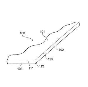
Figure 1 ¨ shows a perspective view of a portion 100 of a vaporizer according
to the present
disclosure.
Figure 2¨ shows a perspective view of a vaporizer 100 according to the present
disclosure.
12
CA 02951511 2016-12-07
WO 2015/198049 PCT/GB2015/051845
Figures 3A, 3B and 30 ¨ show plan and end views of a vaporizer 100 according
to the present
disclosure.
Figure 4 ¨ shows an exemplary region of contact between a vaporizer 100 and a
matrix 150.
Figure 5 ¨ shows further exemplary regions of contact between a vaporizer 100
and a matrix 150.
Figure 6 ¨ shows a vaporizer 200 according to the present disclosure.
Figure 7 ¨ shows a graphical representation of the temperature gradient formed
in the vaporizer
100.
Figure 8 ¨ shows the distribution of the electric power released across
vaporizers according to the
present disclosure containing no slots (left), 7 slots (middle) and 4 slots
(right).
Figure 9 ¨ shows the relative temperature distribution and gradients of the
vaporizers shown in
Figure 8.
Figure 10¨ shows a plan view of a device 7 incorporating a vaporizer assembly
according to the
present disclosure.
Figure 11 ¨ shows a cross section view of the device 7 of Figure 10.
Figure 12¨ shows a longitudinal cross section of a further vaporizer assembly
according to the
present disclosure.
Figure 1 shows a portion of a first vaporizer 100 according to the present
disclosure. The
vaporizer 100 has a first surface 101 and a second surface 102. The first and
second surfaces
form a common edge 110. Figure 1 also shows a further surface 103 which forms
an independent
common edge 111 with the first surface 101 and also forms a common edge 112
with the second
surface 102. As will be appreciated from Figure 1, the surface area of the
first surface 101 is
greater than that of the second surface 102.
Figure 2 shows vaporizer 100 and in this instance vaporizer 100 has a
rectangular profile. It will be
appreciated that the vaporizer 100 shown in Figure 2 has four surfaces which
each form
independent common edges with the first surface 101 In this regard, second
surface 102 and
fourth and fifth surfaces 104, 105 are depicted in Figure 3A, 3B and 30.
The interaction between the vaporizer 100 and the matrix 150 is shown in
Figure 4. In particular,
the matrix 150 is in contact with the vaporizer via second surface 102. More
precisely, second
surface 102 of vaporizer 100 contacts surface 151 of matrix 150.
As described above, in some instances the matrix 150 may be in contact with
more than one
surface of the vaporizer 100. Such an arrangement is depicted in Figure 5,
where matrix 150 has
13
CA 02951511 2016-12-07
WO 2015/198049
PCT/GB2015/051845
a surface 151 in contact with the vaporizer 100 via second surface 102 as well
as surface 153 in
contact with the vaporizer 100 via third surface 103.
Figure 6 shows a further vaporizer 200 which has a first surface 201, and
multiple further surfaces
202, 203, 204, 205, 206 each of which independently form a common edge 210,
211, 213, 214,
215 with the first surface 201. It will be understood that any of the multiple
further surfaces shown
in Figure 6 can be considered to be the second surface. Consequently, one or
more matrixes may
be in contact with the vaporizer via any one of the surfaces 202, 203, 204,
205, 206. As described
above, a single matrix may be in contact with more than one of said surfaces
and/or more than one
matrix may be present and each may be in contact with one or more of said
surfaces. Although
not depicted in Figure 6, the surfaces opposite to and parallel with surface
203 may also be in
contact with a matrix_
It should also be noted that the matrix need not contact the entire second
surface of the vaporizer
assembly. However, this may be advantageous in order to establish a great
degree of contact (and
potentially flow of liquid) between the matrix and the vaporizer.
It will be appreciated from the above that the one or more matrixes contacts
the vaporizer(s) along
a "side" face, i.e. one or more of the surfaces forming a common edge with the
first surface. This
contact face is referred to as a "side" face owing to the configuration that
results from the first
surface having a surface area greater than that of the second surface. Such a
configuration may
be particularly advantageous as when the vaporizer is operational the liquid
drawn from the matrix
can be distributed substantially along the entire length of the vaporizer
without compromising the
evaporating efficiency of the vaporizer. Furthermore, by ensuring that contact
between the
vaporizer and the matrix occurs via the second surface as mentioned herein,
the first surface can
be left free of contact so that any liquid vaporized by the vaporizer can exit
the vaporizer freely.
This is typically advantageous where the vaporizer 100, 200 assembly is
incorporated into devices,
such as e-cigarettes, where the flow of air through the device will pass over
the first surface
101,201 of the vaporizer 100,200 and thus the vapor produced by the vaporizer
100, 201 is able to
form an aerosol more effectively.
The specific orientation of the vaporizer and the matrix of the present
assembly is also
advantageous in that it provides for a graduated vaporization profile across
the vaporizer. Due to
liquid being delivered to the vaporizer via the "side" face of the vaporizer,
a vaporization or
temperature gradient is established across the width of the vaporizer 100,200.
Without being
14
CA 02951511 2016-12-07
WO 2015/198049
PCT/GB2015/051845
bound by theory, this gradient is formed at least in part because of the
greater proximity of the
second (side) surface of the vaporizer to the matrix compared to the centre of
the vaporizer. The
relative flow of liquid through this portion of the vaporizer is therefore
greater than towards the
centre of the vaporizer and therefore the temperature of the vaporizer in
these areas is depressed
to a greater extent. Furthermore the unheated and usually more voluminous
matrix forms a heat
sink for the heated vaporizer. This vaporization gradient is particularly
advantageous if the liquid to
be vaporized contains multiple substances having different boiling points. The
natural action of the
capillary structure formed in the vaporizer 100, 200 will draw the liquid
inwards from the matrix 150
via the side face (second surface as defined herein) and as a result of the
vaporization gradient the
vaporizer simultaneously evaporates multiple substances having different
boiling points. For
example, where the liquid to be vaporized contains nicotine, water and
glycerol, each of which has
a different boiling point, each substance can be vaporized substantially
simultaneously leading to
an aerosol with a more balanced profile. An example of the gradient
established across the
vaporizer 101 is shown in Figure 7. It will be appreciated that this gradient
is generally established
when the vaporizer is configured to be fed with a vaporizable liquid in a
direction substantially
perpendicular to the longitudinal axis of the vaporizer.
As described above, the vaporizer of the present disclosure may include one or
more slots
extending from the second surface of the vaporizer into the first surface.
Vaporizers having such
slots are shown in Figures 8 and 9, alongside a vaporizer having no such
slots. As can be seen
from Figures 8 and 9, the electrical power (power distribution) is influenced
by the presence of the
slots. When no slots are present, the electrical power generated and energy
released across the
device/ vaporizer surface 101 is substantially constant Such a uniform
generation of power/
release of energy does not, however, lead to a constant temperature profile
across the vaporizer
as a result of the orientation of the vaporizer and matrixes, as explained
above and shown in
Figure 7. The temperature gradient induced in the vaporizer is shown again in
Figure 9.
However, when one or more slots are included in the vaporizer, as for example
shown in Figures 8
and 9, the generation of electrical power/ release of energy is not constant
across the vaporizer
and instead peaks around the tips of the slots. These peaks in the generation
of electrical power/
release of energy arise due to the disruption of the electrical current
flowing longitudinally through
the vaporizer and they lead to areas of increased temperature. This can be
seen in Figure 9,
where in addition to the temperature gradient induced by the arrangement of
the vaporizer and the
matrixes, a further re-inforcing temperature gradient is induced. The
provision of slots helps
keeping the generation of power/ release of energy away from the second
surface, where the
CA 02951511 2016-12-07
WO 2015/198049 PCT/GB2015/051845
energy would otherwise (no slots) be immediately absorbed by the matrix which -
as explained
above - can be considered as a heat sink. As a result the slots are increasing
the evaporation
efficiency.
As described above, the vaporizer assembly may contain more than one matrix.
In particular,
Figure 10 depicts a device 7, such as an e-cigarette, comprising a vaporizer
assembly comprising
first and second vaporizers 2A, 2B, each vaporizer being in contact with a
respective matrix 3a, 3b,
3c via multiple surfaces of the vaporizer, each surface forming an independent
edge with the
respective first surface of each vaporizer. More precisely, matrix 2A is in
contact with vaporizer 3a
via a second surface of the vaporizer 2A, the second surface forming a common
edge with the first
surface of the vaporizer 2A. Further, matrix 3b is also in contact with
vaporizer 2A via a further
surface, the further surface forming an independent common edge with the first
surface of the
vaporizer 2A. Additionally, matrix 3b is in contact with vaporizer 2B via a
second surface of the
vaporizer 2B, the second surface forming a common edge with the first surface
of the vaporizer 2B.
Further, vaporizer 2B is also in contact with matrix 3c via a further surface,
the further surface
forming an independent common edge with the first surface of the vaporizer 2B.
In this way,
multiple vaporizers can cooperate with multiple matrixes in the vaporizer
assembly so as to provide
mutual support and efficient supply of liquid to the vaporizers.
As described above, the vaporizers 100, 2A, 2B, 200 may include portions at
the distal and
proximal ends which are adapted to provide electrical contacts. These portions
of the vaporizers
are depicted in Figure 10 as U+ and U-. Furthermore, in some embodiments, a
bridge 6 is present
which provides electrical communication between multiple vaporizers so as to
simply any electrical
connections that may be required.
Figure 11 shows a cross-sectional profile of device 7 (transverse to the
longitudinal dimension of
the device). As explained above, device 7 includes vaporizers 2A and 2B,
matrixes 3a, 3b, 3c, and
channels 4', 4" formed above and below vaporizer 2A and channels 5', 5" formed
above and below
vaporizer 2B. Said channels are formed by the upper and lower major surfaces
of the vaporizers,
the side surfaces of the matrixes 3a, 3b, and 3c, as well as the inner walls
of housing 1.
As described above, such an arrangement allows the vaporizers to cooperate
with multiple
matrixes in the vaporizer assembly so as to provide mutual support, efficient
supply of liquid to the
vaporizers and also the ability to form vaporization gradients across each
vaporizer whilst at the
same time ensuring that the first surfaces (upper surfaces as depicted in
Figure 11) remain
substantially or completely contact free. This ensures efficient provision of
vapor to any air
16
CA 02951511 2016-12-07
WO 2015/198049 PCT/GB2015/051845
channel formed above the vaporizers. Of course, the same applies to the
surfaces (lower surfaces
as depicted in Figure 11).
The device 7 encloses the vaporizers and matrixes by a device wall 1. The
device wall 1, also
referred to as a housing, may encompasses/defines other features/components
typically found in
e-cigarettes: a mouthpiece; an air inlet and air outlet interconnected by
channels 4', 4", 5', 5"; a
battery; a PCB, various sensors and microprocessors used to operate the device
in response to
use of the device (e.g. inhalation though the mouthpiece); and one or more
LEDs. The device 7
depicted in Figure 11 is not intended to be limiting and any combination of
vaporizers and matrixes
as described herein can be incorporated into a suitable device.
Device 7 is generally operated as follows. A user places the mouthpiece of the
device to his/her
mouth and inhales, thereby causing air to flow through the device. Said air
flow (or reduced
pressure) is detected by the sensor in the device, which then relays
information to the
microprocessor that the device is in use. Power is then delivered to the
vaporizer and, owing to
the electrical resistance of the vaporizer, the temperature of the vaporizer
increases. Due to the
capillary effect induced by the capillary structures of the vaporizer and
matrix and due to the
contact between the vaporizer and the matrix (which contains a liquid to be
vaporized) liquid is
drawn by capillary force from the matrix to the vaporizer. Accordingly, as the
temperature of the
vaporizer increases various substances contained within the vaporizable liquid
are vaporized. As
described above with regard to Figure 7, owing to the contact of the vaporizer
with the matrix via
the second surface, a temperature gradient is set-up across the vaporizer. In
particular, the
temperature of the vaporizer generally increases away from a surface in
contact with the matrix.
Therefore, with regard to device 7, each vaporizer 2A and 2B will display a
greater temperature at
its center compared to the temperature at the surface in contact with the
respective matrixes 3a, 3b
and 3c. During operation of the device, vapor is expelled from the vaporizers
2A and 2B into the
channels 4', 4", 5' and 5". Air flowing through the device 7 also travels
through channels 4', 4", 5'
and 5" and as a result mixes with the expelled vapor The vapor cools and
condenses to form an
aerosol which travels through the device 7 to the mouthpiece and is inhaled by
the user. As
vapor is expelled from the vaporizers 2A and 2B, further liquid is drawn from
the matrixes 3a, 3b
and 3c and the volume of liquid present inside the vaporizer is replenished.
Once the users
ceases inhalation, the sensor within the device detects the relative change in
flow (or pressure)
and communicates this to the microprocessor, following which the power to the
vaporizer is
terminated, the temperature of the vaporizer drops and liquid ceases to be
vaporized (at least to
the same extent as during operation). Alternatively, the power to the
vaporizer may be terminated
17
after a certain period of time (e.g. 2 seconds after start of inhalation) has
elapsed. Following
the signal from the sensor that the device 7 is in use the microprocessor may
also cause
other functions to be activated, such as operation of one or more LEDs etc.
.. A further embodiment of a vaporizer assembly according to the present
disclosure is shown
in Figure 12. The vaporizer assembly depicted in Figure 12 comprises a matrix
250 which is
tubular and a vaporizer 100 which is dimensioned as shown in Figure 2. In
particular,
vaporizer 100 has a first surface 101 and second surfaces 102 and 104. Second
surfaces
102 and 104 are in contact with surfaces 251 and 252 of matrix 250. The
orientation of
vaporizer 100 within tubular matrix 250 is such that air channels 300 are
formed above and
below the vaporizer 100. Matrix 250 may be made of a resilient material.
Further, the inner
diameter of matrix 250 may be slightly smaller than the width of vaporizer 100
so that
vaporizer 100 is supported by matrix 250 (via, for example, friction fit/the
resilient nature of
matrix 250).
Various modifications and variations of the described vaporizer assembly and
device
incorporating the same will be apparent to those skilled in the art without
departing from the
scope and spirit of the disclosure. Although the invention has been described
in connection
with specific embodiments, it should be understood that the invention as
claimed should not
be unduly limited to such specific embodiments. Indeed, various modifications
of the
described modes for carrying out the invention which are apparent to those
skilled in the art
or related fields are intended to be within the scope of the following claims.
18
CA 2951511 2019-03-29