Note: Descriptions are shown in the official language in which they were submitted.
CA 02951764 2016-12-16
400-4 CA
Synergic method for hydrodynamic energy generation with neutralized head
pressure pump
FIELD OF THE INVENTION
The present invention relates to the field of energy production and
utilization, and more specifically relates to the field of energy production
via hydrodynamic sources.
BACKGROUND OF THE INVENTION
A power generating station is an industrial machine or plant for the
generation of mechanical, hydrodynamic or electric power. At the center of
nearly all power generating stations is a generator, which typically
includes a rotating machine that converts mechanical power into electrical
power by creating relative motion between a magnetic field and a conductor.
The energy source harnessed to turn the generator varies widely----from moving
water and wind, to fossil fuels (such as coal, oil, and natural gas) and
nuclear material. In recent times, however, due to the decreasing reserves
of fossil fuels and the environmental impact of their use in power generation,
cleaner and abundant alternatives for the generation of power have become
more popular. One of the cleaner alternatives is hydropower; however,
hydropower is limited by size of lakes held in reservoirs or behind dams.
Such water has a potential power that, when released, will be delivering
energy in a certain form. The standard form utilized nowadays is allowing
water flow to rotate a turbine at maximum velocity point of the energy curve
of the turbine to generate maximum power. In one theoretical example, in
a 200 foot high system, 5 feet diameter Wheel/Turbine, 30" bucket area,
at 400 GPM flow we calculated 15 KW theoretically available power, which
if deployed to multiple pumps to pumping water back to 200 feet high, at
40% efficiency, we may expect about 160 GPM pumping output. In our method,
we utilized same potential energy over same turbine, to directly drive a
pump, by utilizing another, higher torque point of the energy curve, at about
10% turbine velocity and 90% of torque (by controlling and lowering flow
using a valve under turbine), such method will not change the value of
available potential power, but instead will move the point of energy
utilization on curve toward maximum torque, minimizing flow to 40 GPM, and
also minimizing available power to 1.5 KW, however adding to the shafts
additional driving force of about 2600 lbf, (and a torque output energy
equivalent to about 4500 ft-lbf) where 1 ft-lbf is enough energy to lift
one pound, one foot vertically per second, allowing theoretically to pump
1
CA 02951764 2016-12-16
400-4 CA
about 160 gallons per minute to 200 feet high reservoir, with only 40 GPM
down flow, In this alternative method, we have 120 GPM net pumping gain
available to be dropped back over second turbine in a 200 feet high housing,
to generate what we calculated about 4 KW energy as usual but without
depleting the upper reservoir or lake.
With regard to the economy of energy generation, theoretical calculations
show that having at least two turbines and a pump in sequence, as per the
above-described method, yields similar number of Watts generated per Gallon
of flow by the last in series turbine, but without depleting upper reservoir
or lake behind a dam. Energy production then is only limited to the number
of utilized turbines rather than the size of the lake behind the dam or the
size of the upper reservoir. Limits on the amount of energy available from
hydrodynamic installations will be eliminated and hydrodynamic energy may
cover 100% of our human energy needs. The cost of already cheap but limited
hydrodynamic energy production will further decrease when a Dam' s potential
of energy utilization is increased
Hydropower is limited. Hydroelectricity refers to electricity generated by
hydropower, i.e., the production of electrical power through the use of the
gravitational force of falling water. However, the limited availability of
hydropower may be solved by utilizing synergic assemblies of turbines where
we may have the energy production process pass into multiple steps before
finally a certain controlled flow may be advanced to production turbine,
and where the net energy produced, is dependent on height and number of
turbines. The alternative method shall consist of at least two turbines and
pumping device per assembly.
Pump utilization of energy increases with high head pressure. Another major
problem with hydroelectric power, is in low utilization times, where a PSH
system is utilized to save the non-utilized power, by pumping water back
to higher level reservoir to have it regain its potential power, however
the main issue in the PSH method is the low efficiency, where energy is spent
on overcoming high head or resistance. To save power we need to not waste
more power, but instead we need to utilize higher suction torque energy that
may be obtained without requiring high volume of water flow. In our method
high suction torque is delivered to pump or jet from a first turbine to secure
pumping capacity without need to spend more Watts, however the minimal flow
allowed through first turbine will be deducted from the overall pumping
volume to calculate the net pumping volume.
Connecting a pump or jet to a turbine wheel, utilizing a gear or shaft may
create a hoist like levering system but with having the bigger force and
bigger arm (wheel torque and diameter), situated on one side of the lever.
2
CA 02951764 2016-12-16
400-4 CA
In an ordinary hoist, such set up results in distance gain causing the hoist
wire to allow utilization limited to the length of the wire. In our system
water flow replaces the hoist wires and the gain in distance is actually
a gain in pumping flow speed, where for every gallon falls from top to bottom
of the housing to driving the wheel, we have more gallons pumped from bottom
to top of the housing causing net gain in gravitational energy storage. FIG.
12
Therefore, a need exists to overcome the problems with the prior art as
discussed above, and particularly for a more efficient way of providing
cleaner, more abundant, more environmentally friendly and recycling
alternatives for power generation, namely, hydroelectric power generation.
SUMMARY OF THE INVENTION
A method for hydrodynamic energy generation and neutralized head pressure
pump assembly is provided. This Summary is provided to introduce a selection
of disclosed concepts in a simplified form that are further described below
in the Detailed Description including the drawings provided. This Summary
is not intended to identify key features or essential features of the claimed
subject matter. Nor is this Summary intended to be used to limit the claimed
subject matter's scope.
In one embodiment, the method for hydrodynamic energy generation includes
providing a housing comprising a hollow interior, pumping water via the
housing using a pump located at a bottom of the housing, the pump equipped
with a first fluid inlet routing fluid from a high head pressure turbine
compartment, and a second fluid inlet that routes fluid from a second low
head compartment. providing a first vertically aligned compartment within
the housing, wherein the first vertically aligned compartment has a first
opening on an upper end and a second opening on a lower end, which interfaces
with the first fluid inlet, mechanically coupling a first water wheel,
located below the first opening on the lower end and within the first
compartment, to pump assembly. A pumping jet is moved when the first water
wheel is moved by water that falls into the first compartment, providing
a flow control valve at the second opening of the first compartment,
providing a second vertically aligned compartment within the housing,
wherein the second compartment has a first opening on an upper end and a
second opening on a lower end, which interfaces with the second fluid inlet,
mechanically coupling a second water wheel, proximate to the second opening
of the second compartment, to a generator for generating electrical or
mechanical rotational power, by the generator, when the second water wheel
is moved by means of water flow which then exits the lower end of the second
compartment, reading data from a controlled water level under the second
3
CA 02951764 2016-12-16
400-4 CA
turbine, providing a third vertically aligned compartment within or beside
the housing, wherein the third compartment has a first opening on an upper
end and a second opening on the lower end, wherein the upper end of the third
compartment is in fluid communication with the first and second compartments,
providing a fourth compartment within the housing arranged proximate to the
lower ends of the first, second and third compartments, wherein the second
openings of the first, second, and third compartments provide fluid
communication with the fourth compartment, a pump or external jet for
removing water from the fourth compartment into the third compartment,
wherein the pump is mechanically coupled to the first water wheel through
the external gear box, shaft or chain and at least partially powered by the
generator or by external power source, and, conductively coupling the
hydrodynamic energy generation system with the external power source via
a coupling.
The foregoing and other features and advantages will be apparent from the
following more particular description of the preferred embodiments, as
illustrated in the accompanying drawings.
BRIEF DESCRIPTION OF THE DRAWINGS
The subject matter, which is regarded as the invention, is particularly
pointed out and distinctly claimed in the claims at the conclusion of the
specification. The foregoing and other features and also the advantages of
the invention will be apparent from the following detailed description taken
in conjunction with the accompanying drawings. Additionally, the left¨most
digit of a reference number identifies the drawing in which the reference
number first appears.
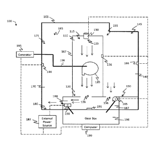
FIG. 1 is a diagram illustrating the hydrodynamic energy generation system,
in accordance with one embodiment.
FIG. 2 is a diagram of a neutralized head pressure pump, in accordance with
alternative embodiment
FIG. 3 is a flow chart depicting the method of the hydrodynamic energy
generation system, in accordance with one embodiment.
FIG. 4 is a block diagram of a system including an example computing device
and other computing devices.
FIG. 5 is a diagram of a pressure neutral pump inlets flow, in accordance
with one embodiment.
4
CA 02951764 2016-12-16
400-4 CA
FIG. 6 is a diagram illustrating a gear system and water wheel of the
hydrodynamic energy generation system, in accordance with yet another
alternative embodiment.
FIG. 7 is a diagram illustrating energy curve utilization of each turbine
of the hydrodynamic energy generation system.
FIG. 8 is a flow chart illustrating the method of synergic management of
potential energy utilization.
FIG. 9 is a diagram illustrating method of mechanically communicating a
water equilibrium forces.
FIG. 10 is a diagram illustrating example and flow method of neutralized
pressure pump.
FIG. 11 is a diagram illustrating an internal jet and water wheel of the
hydrodynamic energy generation system, in accordance with yet another
alternative embodiment.
FIG. 12 is a diagram illustrating levering system example of distance gain
when both big force and big arm are situated on one side of the lever. System
water flow in the example resembles a chain in a pulley hoist.
DETAILED DESCRIPTION
The following detailed description refers to the accompanying drawings.
Wherever possible, the same reference numbers are used in the drawings and
the following description to refer to the same or similar elements. While
embodiments of the invention may be described, modifications, adaptations,
and other implementations are possible. For example, substitutions,
additions, or modifications may be made to the elements illustrated in the
drawings, and the methods described herein may be modified by substituting,
reordering, or adding stages to the disclosed methods. Accordingly, the
following detailed description does not limit the invention. Instead, the
proper scope of the invention is defined by the appended claims.
In accordance with the embodiments described herein, a neutralized pressure
pump in the bottom of a hydrodynamic energy generation system is disclosed
that overcomes the problems with the prior art as discussed above, by
providing an energy generation system that utilizes efficient, clean,
renewable energy and does not produce waste. As an improvement over
conventional energy generation systems, the disclosed systems allows for
the production of energy through unique utilization of potential energy of
5
CA 02951764 2016-12-16
400-4 CA
falling water that is plentiful and renewable or a recycled method, without
the drawbacks of burning fossil fuels--i.e., waste products. Also, the
hydrodynamic energy generation system provides a system with a minimal
number of component parts, thereby reducing the potential for failure or
malfunction of its combination parts. Further, the minimal number of
component parts allows for quick and inexpensive fabrication of the
combination parts, thereby resulting in an economical system. Lastly, the
hydrodynamic energy generation system is easily maneuverable, easily
transportable, inexpensive to manufacture and lightweight in its physical
characteristics.
In this embodiment, high pressure forces working against pumping efforts
will be utilized in a favorable direction, by circulating fluid through a
second pump inlet, to drive a water wheel, which is in turn coupled through
gears to driving the pump. For such utilization to be possible, we needed
to have two inlets before the pump, a gear box shaft or chain that allows
the coupling of the water wheel and the pump FIGS. 6 & 7. It is not the first
time in history to use opposing force energy in favorable direction and the
good example is the work of Herman Fottinger around 1904 who was able to
benefit from the hydrodynamic energy of the water jet created behind a ship,
by changing its force direction through a hydrodynamic transmission, and
to apply its force to rotate the engine of the ship. In his case the water
jet was already there and needed a method to apply its force, in opposite
direction, to help driving the ship engine. In our case we needed to create
the path of such hydrodynamic movement behind the pump, to peripherally
contact and drive a water wheel, which is mechanically coupled to drive the
pump.
The embodiments of the hydrodynamic energy generation method and system will
be described heretofore with reference to FIGS. 1 through 12 below.
FIG. 1 is a block diagram illustrating the hydrodynamic energy generation
method and system 100, in accordance with one embodiment. In one
non-limiting embodiment, the method and system 100 may include a housing
105 or other vertically aligned element, comprising a hollow interior. The
housing may comprise a tubular shaped body, and may, alternatively,
integrate a horizontal part or different portions in a variety of sequences
or configurations. In other embodiments, the housing can comprise a cube
or other hollow shaped bodies. The housing can comprise material having
properties capable of containing water such as aluminum, alloys, iron, glass,
ceramic, plastic any combination thereof. The hydrodynamic energy
generation system 100 may be fully or partially submerged in a body of water
(such as an ocean, lake or river).
6
CA 02951764 2016-12-16
400-4 CA
The housing has vertically aligned at least three compartments. However,
in a submerged configuration, one or more compartments may be replaced by
surrounding media of a lake or reservoir. In the present embodiment, the
first vertically aligned compartment 110 (called a gravity preferred
compartment) is located between the second vertically aligned compartment
140 (Called a pressure preferred compartment) and the third vertically
aligned compartment 170 (called a buoyancy preferred compartment of fluid
movement, where buoyancy promotion factors may be applicable to help fluid
move in the upward direction). However, this is not be a limitation and the
first compartment can be positioned in other configurations. A fourth
compartment 187 is located within the housing and proximate to the lower
ends of the first, second, and third vertically aligned compartments and
comprises in part, the feeding path of the pump. The fourth compartment may
positioned be below the second compartment spanning the entire lower end
of the first compartment. The fourth compartment may also be positioned such
that a portion of the second and third compartments are positioned on top
of the fourth compartment and a portion of the second and third compartments
are positioned on the sides of the fourth compartment. However, other
embodiments are within the spirit and scope of the invention.
In the present embodiment the compartments are defined by vertical and
horizontal walls or structures 167 within the housing. The First vertically
aligned compartment within the housing has a first opening 155 on an upper
end 145 and a second opening 156 on a lower end 150 of the compartment. The
second opening of the lower end of the first compartment is configured for
valve controlled fluid to flow or drain from the first compartment into the
fourth compartment, controlling valve may be manually or electronically
adjusted and monitored. A first water wheel and/or turbine 165 is proximate
to the second opening of the first compartment. The water flow through
opening 156 is configured to move in a peripheral contact around the water
wheel 165 and may be jet directed using an internal jet powered by external
power source FIG. 11, The first waterwheel or turbine is mechanically
coupled to pump through a shaft or gearbox (or reverse speed reducer) 196
that produces rotational power when the first waterwheel is moved by water
exiting the lower end of the first compartment. The first waterwheel and/or
turbine may comprise a rotating machine that converts hydrodynamic power
into mechanical power that drives a gear box 196 (further illustrated in
FIG. 6 and explained below), which produces and manipulate a rotational
power between the first Water wheel disk (165) and the external jet pump
(190) disk. The amount of rotational torque power generated by the first
turbine is proportional to the elevation of the first compartment and
surface area of the first wheel pressing buckets.
The second vertically aligned compartment has an upper end 115 and an
7
CA 02951764 2016-12-16
400-4 CA
opposing lower end 120. A first opening 125 is located at the top end of
the second compartment and configured to allow water to flow into the second
compartment. A second opening 126 is located at the lower end of the second
compartment and is configured to allow water to flow out of or exit the second
compartment and flow into the fourth compartment 187. The present embodiment
may further include a valve 130 coupled to the upper end of the second
compartment for controlling and regulating an amount of water that enters
the opening at the upper end of the second compartment through the first
opening and the water level at the bottom of the second compartment in
coordination with special water level sensor and also in coordination with
pump flow rate. The valve 130 may comprise one or more valves for regulating
flow of water, such as a ball valve, a butterfly valve, a gate valve, a globe
valve, a needle valve, a spool valve or a safety valve. The valve 130 may
further be a check valve or foot valve, which are unidirectional valves that
only allow water to flow in one direction.
The present embodiment may also include energy production water wheel and/or
turbine 135 (chained or otherwise mechanically coupled with a generator 195),
wherein the water wheel 135 and/or turbine is located below the valve 125.
The generator produces electrical power when the water wheel 135 and/or
turbine is moved by the water entering the opening 125 and falling into the
interior of the first compartment. The water wheel 135 and/or turbine may
comprise a rotating machine that converts hydrodynamic power into
mechanical power that drives the first generator (and/or another set of
water pumps) , which produces electrical power. The amount of power generated
by the generator is proportional to the amount of water falling into the
second compartment and is further proportional to the distance from the
opening 125 to the first turbine.
The third vertically aligned compartment 170 within the housing has a first
opening 185 on the upper end 175 of the third compartment and a second opening
188 at the lower end 180 of the third compartment. The upper end of the third
compartment is in fluid communication with the first and second compartments
such that water can flow from the first opening 185 of the third compartment
into the first and second compartments via the first and second
compartments' first openings 125, 155. The second opening of the lower end
of the third compartment is configured for fluid to flow or be pumped from
the fourth compartment into the third compartment.
The fourth compartment 187 within the housing is positioned proximate to
the lower ends of the first, second and third compartments. The fourth
compartment is configured such that the second openings at the lower ends
of the first, second and third compartments provide fluid communication with
the fourth compartment. Additionally, valves may be used at the openings
8
CA 02951764 2016-12-16
400-4 CA
of all the compartments to control the flow of fluid or water between the
compartments. Such valves may comprise one or more valves for regulating
flow of water, such as a ball valve, a butterfly valve, a gate valve, a globe
valve, a needle valve, a spool valve or a safety valve. The valve may further
be a check valve or foot valve, which are unidirectional valves that only
allow water to flow in one direction.
A pump 190 or external jet for moving water from the fourth compartment 187
into the third compartments 170 is positioned proximate to the second
opening of the third compartment. The pump is mechanically coupled to the
shaft, chain or gear box 196 and is adapted so that it can be at least
partially powered by the generator or an external power. In other
embodiments additional pumps may be used, as in FIGS. 2 & 6. The pump, or
any other item of the present embodiment (like first wheel, alternatively
driven by external power) that may require electricity can be coupled (via
a conductive coupling) and powered via an external power source. Such
external power source maybe the utility power grid or another power producer,
such as solar power, wind power, hydroelectric power, nuclear power, battery
power etc.
The structure comprised of pump 190, the forth compartment, the first
turbine (165), the low fluid head pressure opening or inlet (126) and the
high fluid head pressure route opening (156) and the external gear box
(reverse speed reducer) all together comprises a "neutralized pressure
pump" where head pressure applied to driving first turbine is equal (or more
as fluids start to acquire speed) than head pressure faces the external jet
at any given elevation and as a result, the pump head pressure is
alternatively calculated by head torque of pump jet or impellers wherein
(head torque=pump load torque-first turbine torque output).
In the event the method and system 100 is a net consumer of energy, the system
100 has the utility identical in certain dynamics to a pumped storage
hydroelectricity system. However the disclosed system is different in that,
due to the installation under the surface of a body of water, or due to equal
elevation of water in first and third compartments and presence water
equilibrium forces, pumping water does not require more energy, when the
elevation between the level of storage (or water return level) and the level
of pumping is increased due to using equal or balancing values of challenging
head pressure that faces the pump and of the first turbine driving torque
force through, connected gear box, in driving the pump rotational energy.
As is well known in the art, pumped-storage hydroelectricity is a net
consumer of energy and yet has a known utility. Pumped-storage
hydroelectricity (PSH) is a type of hydroelectric energy storage used by
electric power systems for load balancing. The method stores energy in the
9
CA 02951764 2016-12-16
400-4 CA
form of gravitational potential energy of water, pumped from a lower
elevation reservoir. Low-cost off-peak electric power is used to run the
pumps. During periods of high electrical demand, turbines produce electric
power. Although the losses of the pumping process make the plant a net
consumer of energy overall, the system increases revenue by selling more
electricity during periods of peak demand, when electricity prices are
highest. This same utility may apply to system 100, however better return
may be calculated.
In above ground installations of PSH systems, pumping water to higher levels
of storage consumes higher energy which is wasted to overcome higher head
pressure, and remains at all times energy net negative. In the disclosed
system, however, while higher energy in deeper systems may be obtained from
water falling through an opening, pumping a fixed amount of water out of
the system consumes a similar amount of energy at different levels of depth,
due to neutralizing the pressure factor in the known pumping formula, by
using the gear box between the external jet pump (190) and first turbine
(165). The formula in general is, (increase in pumping energy=change of head
pressure*flow), and in our system, a change of head pressure is eliminated
by mechanically communicating water equilibrium forces as in FIG. 9,
regardless of pumping elevation. And the formula is (pumping
energy=1*system constant*flow) where 1 in the formula, replaces the change
of head pressure upon charges of system height, and is the ratio of head
pressure in third compartment to the head pressure in first compartment,
and where system constant is different according to system specs, which
means both flow and pumping energy remain the same regardless of elevation,
thereby giving rise to the potential that at a certain depth, the energy
produced may exceed energy consumed. In the disclosed system, if the falling
water produces more energy as the system is deployed in a deeper depth and
when discharging this falling water consumes the same amount of energy
regardless of depth, then the disclosed system may at a certain depth reach
the level of being a net producer of energy. Such gain is not produced from
breaking physics laws, but rather from synergic management is a system open
to potential energy where by definition of thermodynamics, a system is not
considered to be closed if opened to potential energy. However, the existing
practice of utilizing potential power is limited to flow (where produced
energy is relevant to system height and flow over a turbine), while in this
system we have alternative utilization, wherein the first turbine, produced
torque is energy relevant to system height and bucket surface area and wheel
size. Secondly, when the diameter ratio of the first turbine disk (165) and
the driving disk of external jet or pump (190) is bigger than 1, then based
on such ratio we may, establish secondary gain in gravitational energy
storage upon gain in torque head of the pump, that may be translated into
gain in pumping flow speed or volume, based on hoist levering calculation
CA 02951764 2016-12-16
400-4 CA
discussed here above.
The hydrodynamic energy generation method and system 100 may further be
mechanically stationed and fixed steady in place, such as attaching the
system to one or more concrete pads, metal constructions or any other fixed
support. In one embodiment, the housing includes a filter coupled to the
valves at the top of the housing, wherein the filter eliminates unwanted
debris from the water flowing through the valves. It is desirable to
eliminate the intake of debris and other unwanted material so as to reduce
or eliminate clogs and other malfunctions.
The present embodiment may further include a first sensor 136 for detecting
water flow and level as water falls into the second compartment 110 via the
opening 125. The first sensor may be an accelerometer, a water flow sensor,
a temperature sensor, a conductance measurement device, a barometer, a
pressure sensor, etc. The present embodiment may also include a second
sensor 166 for detecting an amount of water flowing into the first
compartment 140. The second sensor may be an accelerometer, a water flow
sensor, a temperature sensor, a conductance measurement device, a barometer,
a pressure sensor, etc. The present embodiment may also include a third
sensor 186 for detecting an amount of water flowing into the third
compartment 170 and for detecting the level of the water in the third
compartment. The third sensor may be an accelerometer, a water flow sensor,
a temperature sensor, a conductance measurement device, a barometer, a
pressure sensor, etc. The present embodiment may also include a fourth
sensor 191 for detecting an amount of water flowing into the fourth
compartment 187. The second sensor may be an accelerometer, a water flow
sensor, a temperature sensor, a conductance measurement device, a barometer,
a pressure sensor, etc. In FIG. 1, the first, second, third and fourth
sensors may be one integrated unit or may comprise a plurality of sensors
distributed throughout the system and method 100 in different locations.
The present embodiment may further include a computer or control processor
199. The processor may be communicatively coupled with valve 130, first
generator 195, first water wheel or turbine 165, second water wheel or
turbine 135, pump 190, and sensors 136, 166, 186, 191 as well as power source
197 and second generator or gear box 196. In one embodiment, processor 199
may be a central processing unit, microprocessor, integrated circuit,
programmable device or computing device, as defined below with reference
to FIG. 4. The control processor 199 is configured for reading data from
the first, second, third and fourth sensors, first generator, second
generator or gear box, and first and second water wheels or turbines and
sending control signals to the valve and pump and second turbine, wherein
the control signals are configured to activate the valve to regulate an
11
CA 02951764 2016-12-16
400-4 CA
amount of water that enters the first opening of the upper end of the first
compartment, to activate the pump to move water from the fourth compartment
and into the third compartment and to regulate an amount of water maintained
in the first, second and third compartments.
As water moves from the fourth compartment 187 and into the third compartment
170, the water level rises in the third compartment until water flows into
the first and second compartments. As water flows into the second
compartment, gravity forces water to move the second water wheel, situated
above controlled water level. As water flows into the first compartment,
the difference of water level between second compartment and first
compartment while interconnected, forces water to move to the lower end of
the second compartment and into the fourth compartment thereby moving the
first water wheel, by means of head pressure force, as water exits the first
compartment. In the present embodiment, the first water wheel/turbine is
positioned within the fourth compartment proximate to the second opening
of the first compartment. However, in other embodiments, the water wheel
may be positioned proximate to the second opening and within the first
compartment.
FIG. 3 is a flow diagram illustrating the process flow 300 of the operation
of the method and system 100, in accordance with one non-limiting embodiment.
First, in step 302, the first, third and fourth compartments are filled with
water to a certain level using an external power source. The external power
source can be external power source 197. As mentioned above, the external
power source can be generated from the electrical utility grid, solar power,
wind power, nuclear power etc. Next, in step 304, pump 190 is activated to
cause water within the fourth compartment 187 to flow into the third
compartment via opening 188. As the pump moves water into the third
compartment the water level rises of the third compartment rises until water
flows into the first and second compartments. As water begins to fall free
into the second compartment, water flows through the second turbine. As
water passes through the second turbine/water wheel and into the lower end
of the second compartment, the process moves to step 305 and electrical power
is generated via the turbine.
As water continues to flow from the third compartment into the first
compartment 140, the process moves to step 306. In step 306, as water enters
into the first compartment, water flows through the first water wheel as
it exits the first compartment into the fourth compartment via opening 156.
Next in step 308, as water begins to flow into the fourth compartment the
second water wheel or turbine 165, turns and, the gears of gearbox or
generator are rotated generating mechanical power. After the gears are
activated, the process moves to step 310, and the gears or generator can
generate power to at least partially power the pump. In step 309, the pump
12
CA 02951764 2016-12-16
400-4 CA
can be provided power by the external power source 197 in order to partially
power the pump. After the pump is activated, the process moves to step 312.
In step 312, water from compartment one and two entering into compartment
four can be used to continuously raise the water level of compartment three.
As the water level of compartment three raises, the process moves back to
step 304 and is continued until a user desires to terminate the process.
Additionally, in step 314, the power generated by the generator or the power
provided by the external power source and by use to power any component of
the system, as well as to provide power to monitor and regulate the valves
and to control the components of the system.
FIG. 4 is a block diagram of a system including an example computing device
400 and other computing devices. Consistent with the embodiments described
herein, the aforementioned actions performed by computer 199 may be
implemented in a computing device, such as the computing device 400 of FIG.
4. Any suitable combination of hardware, software, or firmware may be used
to implement the computing device 400. The aforementioned system, device,
and processors are examples and other systems, devices, and processors may
comprise the aforementioned computing device. Furthermore, computing
device 400 may comprise an operating environment for the method shown in
FIG. 3 above.
With reference to FIG. 4, a system consistent with an embodiment of the
invention may include a plurality of computing devices, such as computing
device 400. In a basic configuration, computing device 400 may include at
least one processing unit 402 and a system memory 404. Depending on the
configuration and type of computing device, system memory 404 may comprise,
but is not limited to, volatile (e.g. random access memory (RAM)),
non¨volatile (e.g. read¨only memory (ROM)), flash memory, or any
combination or memory. System memory 404 may include operating system 405,
one or more programming modules 406 (such as program module 407). Operating
system 405, for example, may be suitable for controlling computing device
400's operation. In one embodiment, programming modules 406 may include,
for example, aprogrammodule 407. Furthermore, embodiments of the invention
may be practiced in conjunction with a graphics library, other operating
systems, or any other application program and is not limited to any
particular application or system. This basic configuration is illustrated
in FIG. 4 by those components within a dashed line 420.
Computing device 400 may have additional features or functionality. For
example, computing device 400 may also include additional data storage
devices (removable and/or non¨removable) such as, for example, magnetic
disks, optical disks, or tape. Such additional storage is illustrated in
FIG. 4 by a removable storage 409 and a non¨removable storage 410. Computer
13
CA 02951764 2016-12-16
400-4 CA
storage media may include volatile and nonvolatile, removable and
non-removable media implemented in any method or technology for storage of
information, such as computer readable instructions, data structures,
program modules, or other data. System memory 404, removable storage 409,
and non-removable storage 410 are all computer storage media examples (i.e.
memory storage.) Computer storage media may include, but is not limited to,
RAM, ROM, electrically erasable read-only memory (EEPROM), flash memory or
other memory technology, CD-ROM, digital versatile disks (DVD) or other
optical storage, magnetic cassettes, magnetic tape, magnetic disk storage
or other magnetic storage devices, or any other medium which can be used
to store information and which can be accessed by computing device 400. Any
such computer storage media may be part of device 400. Computing device 400
may also have input device (s) 412 such as a keyboard, a mouse, a pen, a sound
input device, a camera, a touch input device, etc. Output device(s) 414 such
as a display, speakers, a printer, etc. may also be included. The
aforementioned devices are only examples, and other devices may be added
or substituted.
Computing device 400 may also contain a communication connection 416 that
may allow device 400 to communicate with other computing devices 418, such
as over a network in a distributed computing environment, for example, an
intranet or the Internet. Communication connection 416 is one example of
communication media. Communication media may typically be embodied by
computer readable instructions, data structures, program modules, or other
data in a modulated data signal, such as a carrier wave or other transport
mechanism, and includes any information delivery media. The term "modulated
data signal" may describe a signal that has one or more characteristics set
or changed in such a manner as to encode information in the signal. By way
of example, and not limitation, communication media may include wired media
such as a wired network or direct-wired connection, and wireless media such
as acoustic, radio frequency (RF), infrared, and other wireless media. The
term computer readable media as used herein may include both computer
storage media and communication media.
As stated above, a number of program modules and data files may be stored
in system memory 404, including operating system 405. While executing on
processing unit 402, programming modules 406 may perform processes
including, for example, one or more of the methods shown in FIG. 3 above.
Computing device 402 may also include a graphics processing unit 403, which
supplements the processing capabilities of processor 402 and which may
execute programming modules 406, including all or a portion of those
processes and methods shown in FIG. 3 above. The aforementioned processes
are examples, and processing units 402, 403 may perform other processes.
Other programming modules that may be used in accordance with embodiments
14
CA 02951764 2016-12-16
400-4 CA
of the present invention may include electronic mail and contacts
applications, word processing applications, spreadsheet applications,
database applications, slide presentation applications, drawing or
computer-aided application programs, etc.
Generally, consistent with embodiments of the invention, program modules
may include routines, programs, components, data structures, and other
types of structures that may perform particular tasks or that may implement
particular abstract data types. Moreover, embodiments of the invention may
be practiced with other computer system configurations, including hand-held
devices, multiprocessor systems, microprocessor-based or programmable
consumer electronics, minicomputers, mainframe computers, and the like.
Embodiments of the invention may also be practiced in distributed computing
environments where tasks are performed by remote processing devices that
are linked through a communications network. In a distributed computing
environment, program modules may be located in both local and remote memory
storage devices.
Furthermore, embodiments of the invention may be practiced in an electrical
circuit comprising discrete electronic elements, packaged or integrated
electronic chips containing logic gates, a circuit utilizing a
microprocessor, or on a single chip (such as a System on Chip) containing
electronic elements or microprocessors. Embodiments of the invention may
also be practiced using other technologies capable of performing logical
operations such as, for example, AND, OR, and NOT, including but not limited
to mechanical, optical, fluidic, and quantum technologies. In addition,
embodiments of the invention may be practiced within a general purpose
computer or in any other circuits or systems.
Embodiments of the present invention, for example, are described above with
reference to block diagrams and/or operational illustrations of methods,
systems, and computer program products according to embodiments of the
invention. The functions/acts noted in the blocks may occur out of the order
as shown in any flowchart. For example, two blocks shown in succession may
in fact be executed substantially concurrently or the blocks may sometimes
be executed in the reverse order, depending upon the functionality/acts
involved.
While certain embodiments of the invention have been described, other
embodiments may exist. Furthermore, although embodiments of the present
invention have been described as being associated with data stored in memory
and other storage mediums, data can also be stored on or read from other
types of computer-readable media, such as secondary storage devices, like
hard disks, floppy disks, or a CD-ROM, or other forms of RAM or ROM. Further,
CA 02951764 2016-12-16
400-4 CA
the disclosed methods' stages may be modified in any manner, including by
reordering stages and/or inserting or deleting stages, without departing
from the invention.
Although the subject matter has been described in language specific to
structural features and/or methodological acts, it is to be understood that
the subject matter defined in the appended claims is not necessarily limited
to the specific features or acts described above. Rather, the specific
features and acts described above are disclosed as example forms of
implementing the claims.
FIG. 6 is a block diagram illustrating the gear box 196 for the energy
generation method and system 100, in accordance with one embodiment. The
gear box may include a second housing 205 that houses gears and the gear
box may be interconnected with a second generator. The first water wheel
or turbine may be mechanically coupled (such as via an axle) to a first set
of gears including a large gear (or disk) 202 and a small gear (or disk)
204, wherein the small gear (or disk) 204 moves at a higher rotational speed
to drive pump 190. Pump 190 pumps or moves water out of the fourth compartment
through opening 188 and directly to the third compartment 170. In one
embodiment, various sets of gears may be chained in sequence to propagate
power to other systems, pumps or sets of gears.
FIG. 8 is a flow chart illustrating synergic management and utilization of
potential energy, where (negative, non-available) potential energy follows
multiple steps before finally utilized as a positive energy of water flow.
The method in this system starts with controlled slow flow at first
compartment step 802, to convert negative potential energy into positive
torque energy when first wheel is moved step 804. Then the gear is activated
and the pump is moved, causing positive torque energy of first wheel to
change into negative (non-available) energy of gravitational energy storage
of pumped water, in step 808. Then net gained gravitational energy storage
is separated by splitting pumped fluid into recirculating flow, step 818,
and net gain flow, as in step 810. Then net gain of negative gravitational
energy storage is converted to positive energy of flow, which causes driving
the second turbine, in step 812. Then power is generated when rotating the
second turbine, which moves the generator, in step 814.
FIG. 9 is a box diagram illustrating amethod of liquid equilibrium balancing
but with communicating the balancing forces of the two sides of system
(compartment 1 & 3) mechanically through the use of (turbine¨gear-pump or
jet).
FIG. 10 is a diagram illustrating the model of flow in a neutralized head
16
CA 02951764 2016-12-16
400-4(1A
pressure pump and the method of utilizing and maintaining negative torque
head regardless of system height (avoiding the increase in pump active head
pressure in higher systems and avoiding as a result the increase in pumping
energy consumption).
FIG. 12 is pulley hoist diagram, illustrating the gain in distance (of chain
movement) when both big force and big arm are situated one side and distance
gain was the purpose of use rather than balancing forces. In this system,
the water flow around first water wheel and around pump jet impellers, with
mechanical gear connection, resemble the movement of the pulley chain. Using
the numbers from above mentioned system specs, we may assert that 40 GPM
of water down flow in the first compartment, may cause pumping output of
about 160 GPM.
17