Note: Descriptions are shown in the official language in which they were submitted.
CA 02951898 2016-12-09
WO 2015/191738 PCT/US2015/035139
Juice Press Apparatus and Methods
BACKGROUND OF THE INVENTION
[0001] The
present invention relates to apparatus and methods for pressing juice from a
foodstuff.
[0002]
Pressing juice from a foodstuff has been known for centuries and has recently
seen
an increase in interest due to the documented health benefits of drinking
juice pressed from
foodstuffs such as vegetables, fruits and nuts, for example. There are many
types of machines for
pressing juice, from extremely large industrial machines to smaller counter-
top machines. Some
machines can process juice on a continuous line basis while others can process
juice on a batch
basis.
[0003] In its
most basic form, juice pressing may involve the cutting or reduction of size
of
the foodstuff (typically called "maceration") so as to increase the surface
area of the food pieces
which increases accessibility of the plant cells containing the juice. The
macerated foodstuff is
then placed in the machine which includes some type of press to compress the
macerated
foodstuff which causes the cells to break open and release the juice. The
juice is separated from
the pressed solids (typically called "cake" or "pomace").
[0004] It is
desirable to extract as much juice as possible from the foodstuff in the
shortest
time possible while also minimizing machine downtime. It is furthermore
desirable to minimize
the time between juice making batches in a batch type pressing machine. It is
yet furthermore
desirable to have a pressing machine which prevents or at least minimizes
travel of the solids
CA 02951898 2016-12-09
WO 2015/191738 PCT/US2015/035139
2
and/or juice from the pressing chamber to other parts of the machine. It is
even furthermore
desirable to have a design which simplifies the cleaning of the machine in
between juicing
operations. While juice pressing machines have been developed that attempt to
address these
desired features, there remains much room for improvement. A need therefore
remains for an
improved juice pressing machine that addresses and meets all of these desired
features.
SUMMARY OF THE INVENTION
[0005] In a first aspect, the present invention provides a juice pressing
machine having a
platen which moves between retracted and extended positions. A pressing
chamber is provided
which is easily removable from the machine for emptying the pressed foodstuff
therefrom
between successive juicing operations. Foodstuff which preferably has been
first macerated may
be held in one or more permeable pressing filters. A filter may comprise an
individual panel of
material or be assembled into a defined form such as a bag, for example. The
one or more filters
are placed in the pressing chamber and the platen is moved to the extended
position within the
pressing chamber. As the platen pushes against the one or more filters and
foodstuff, the
foodstuff and filter(s) move toward the back wall of the pressing chamber and
are pressed
between the chamber back wall and platen.
[0006] The chamber preferably includes opposing side wall surfaces thereof
which act to
support and restrain the opposite sides of the pressing filter(s) which are
exposed along the
opposite sides of the platen. This makes possible the use of a lighter weight
pressing filter since
the risk of the filter rupturing due to pressure exerted on an unsupported
filter surface during
pressing is likewise reduced. Use of lighter weight filters is desirable in
that the cost of the
CA 02951898 2016-12-09
WO 2015/191738 PCT/US2015/035139
3
pressing filter is reduced to the point where the filters may be considered
disposable, much like a
paper coffee filter.
[0007] In a preferred embodiment, the side wall surfaces of the pressing
chamber include
grooves or other features which direct juice flow toward a juice outlet. The
chamber back wall
and/or platen and/or other pressing surfaces may include vertically extending
grooves or other
features which direct juice to the juice outlet which may be located at the
bottom of the pressing
chamber.
[0008] Once a juicing operation has been completed, the pressing chamber
can be removed
from the machine for emptying the pressed filters and solids contents therein.
The empty
pressing chamber may then be rinsed if needed and reattached to the machine
for a subsequent
pressing operation with newly filled filters. The platen may also be easily
removed from the
machine for cleaning as desired.
[0009] In another aspect, the invention provides an innovative funnel
having a neck of a
length which allows the user to mount an empty pressing filter thereon with
the sides of the
funnel neck covering substantially all the side walls of the filter from the
bottom to the open top
thereof. The bottom wall of the filter is not covered as it is located at the
open end of the funnel
neck opposite the upper hopper end thereof. With the filter and funnel placed
inside the pressing
chamber, the user may then fill the funnel neck with macerated foodstuff.
During this time the
filter side walls remain substantially covered by the funnel neck side walls
and hence dry. Once
the funnel neck is filled with macerated foodstuff, the user simply lifts the
funnel out of the
pressing chamber while leaving the filled filter in the chamber and ready for
a pressing
operation.
CA 02951898 2016-12-09
WO 2015/191738 PCT/US2015/035139
4
[00010] The close fit between the funnel neck and the fully open filter
allow removal of the
funnel from the filter without any appreciable movement of the macerated
foodstuff in the filter.
It is important that movement of the macerated food stuff within the filter is
minimized and also
that the side walls of the filter remain dry prior to the pressing operation.
This is because any
movement of the foodstuff and/or wetness of the filter can cause weakness in
the lightweight
fabric and adversely affect the structural integrity of the filter leading to
rupture. The filling of
the filter via the full filter length funnel neck allows a thin and
substantially even width layer of
foodstuff to be formed as the funnel/filter is filled which is not disturbed
as the funnel is
removed from the filter. Without the funnel neck keeping the filter side walls
stationary and dry,
the foodstuff and/or filter could otherwise tumble upon itself, causing an
uneven layer width and
hence an uneven pressing profile across the length of the foodstuff layer, and
also wet the filter
which greatly increases the chance of filter structural failure prior to the
pressing operation. The
full filter length funnel neck also allows for a thinner layer of macerated
foodstuff to be pressed
which is desirable in that a lower pressing pressure may be used to extract
much more juice from
the foodstuff than would be required with thicker layers of foodstuff in the
pressing area. In
thicker layers of foodstuff, juice extraction from the middle layer is very
difficult and does not
yield as much juice than the foodstuff located at the opposite outer layers
which are directly
engaged by respective pressing surfaces.
[00011] The funnel includes at least one but more preferably two or more
necks in spaced,
side-by-side relation to one another such that two pressing filters may be
filled and placed in the
pressing chamber to increase the amount of juice production in a single
pressing operation. In yet
a further preferred embodiment, a pressing plate is positioned between the
necks prior to
depositing the funnel and mounted filters into the pressing chamber. Thus,
once the funnel is
CA 02951898 2016-12-09
WO 2015/191738 PCT/US2015/035139
removed from the filters the pressing plate is positioned between and directly
engages the facing
surfaces of the two filters. The pressing plate preferably includes grooves or
other features
configured to direct extracted juice toward the pressing chamber juice outlet.
DESCRIPTION OF THE DRAWING FIGURES
[00012] The above-mentioned and other features and advantages of this
invention, and the
manner of attaining them, will become apparent and be better understood by
reference to the
following description of the invention in conjunction with the accompanying
drawing, wherein:
[00013] FIG. 1 is a perspective view of one possible embodiment of a juice
pressing
machine in accordance with the invention;
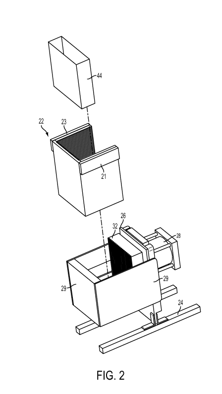
[0001] FIG. 2 is a perspective view of another embodiment of juice pressing
machine and
shown without an outer housing showing the filter, pressing chamber and
pressing chamber
support in spaced relation to the interior of the pressing machine;
[0002] FIGS. 3A and 3B are perspective views of the machine of Fig. 2 shown
without the
outer housing with the movable platen in the retracted and extended positions,
respectively;
[0003] FIG. 4 is a perspective view from the rear of the pressing machine
showing the
platen in the extended condition against a pressing filter held in the
pressing chamber;
[0004] FIG. 5A is a top plan view of the pressing machine of Fig. 2 showing
the area where the
pressing chamber is removably positioned (the pressing chamber and platen are
not shown);
[0005] FIG. 5B is a plan view of the rod-facing surface of the movable platen;
CA 02951898 2016-12-09
WO 2015/191738 PCT/US2015/035139
6
[0006] FIG. 5C is a fragmentary, cross-sectional view showing the interface
between the end of
the pushing rod and the recess of the platen;
[0007] FIG. 5D is a fragmentary, side elevational view with some parts in
cross-section, showing
the platen in an at least retracted position with respect to the pressing
chamber bottom and side
wall and platen support platform;
[0008] FIG. 6 is a perspective view of one preferred embodiment of the
pressing chamber;
[0009] FIG 7A is a perspective view showing the embodiment of a two neck
funnel for filling
two filters with a pressing plate therebetween, all in spaced relation to one
another;
[00010] FIG. 7B is the view of Fig. 3A (absent the single filter in the
chamber) showing
the double-neck funnel and two filters and pressing plate being lowered into
the pressing
chamber of Fig. 6;
[00011] FIG. 7C is the view of Fig. 7B showing the funnel and filters and
pressing plate
positioned with the pressing chamber prior to filling of the filters with
macerated foodstuff;
[00012] FIG. 7D is the view of FIG. 7C with the funnel shown removed from
the filters
leaving the filled filters and pressing plate in the pressing chamber and the
platen in the retracted
position;
[00013] FIG. 7E is the view of FIG. 7D showing the platen in an at least
partically
extended position during a pressing operation;
[00014] FIG. 7F is a perspective view of the pressing chamber and pressed
filters with
cake therein removed from the machine and ready for dumping of the filters
from the pressing
chamber;
CA 02951898 2016-12-09
WO 2015/191738 PCT/US2015/035139
7
[00015] FIG. 8 is a perspective view of another embodiment of a juice
pressing machine
in accordance with the invention;
[00016] FIG. 9 is the view of Figure 8 with the pressing chamber and
chamber support
elements removed;
[00017] FIG. 10 is a side elevational view of Figure 8 with the right
adjacent side walls of
the pressing chamber and the chamber support removed;
[00018] FIG. 11 is a front elevational view of Figure 9;
[00019] FIG. 12 is a top plan view of Figure 8;
[00020] FIG. 13 is a perspective view of the pressing chamber of the
embodiment of
Figure 8;
[00021] FIG. 14 is a top plan view thereof;
[00022] FIG. 15 is an exploded rear perspective view thereof;
[00023] FIG. 16 is an exploded front perspective view thereof;
[00024] FIG. 17 is a rear perspective view of the bottom wall of the
pressing chamber;
[00025] FIG. 18 is a front elevational view of the back wall of the
pressing chamber;
[00026] FIG. 19 is a perspective view of another embodiment of the juice
pressing
machine of the invention;
[00027] FIG. 20 is a top plan view of another embodiment of pressing
chamber for use
with the machine of Figure 19;
[00028] FIG. 21 is a side elevational view of Figure 19 with the right
adjacent side wall of
the pressing chamber removed;
CA 02951898 2016-12-09
WO 2015/191738 PCT/US2015/035139
8
[00029] FIGS. 22A and 22B are assembled and unassembled perspective views;
respectively, of another embodiment of a juice pressing machine in accordance
with the
invention;
[00030] FIGS. 23A and 23B are front perspective and side elevational views,
respectively,
of another embodiment of pressing chamber in accordance with the invention;
[00031] FIG. 24 is a perspective view of another embodiment of a platen in
accordance
with the invention;
[00032] FIG. 25 is a side elevational view of the platen of Figure 24 in
spaced relation to
the frame supporting the push rod and pins of another embodiment of the juice
pressing machine
in accordance with the invention;
[00033] FIG. 26 is a fragmentary cross sectional view of another embodiment
of pressing
surface groove pattern;
[00034] FIG. 27 is a fragmentary cross sectional view of another embodiment
of pressing
surface groove pattern;
[00035] FIG. 28 is a plan view of Figure 26 and further showing an outline
of a segment
of filter on the pressing surface;
[00036] FIG. 29 is a perspective view of another embodiment for filling a
filter with
macerated foodstuff;
[00037] FIG. 30 is a perspective view of the embodiment of Figure 29
showing the
macerated foodstuff being transferred from the tray to the filter;
[00038] FIG. 31 is a perspective view of another embodiment of filter and
frame for
assembling the filter;
[00039] FIG. 32 is a perspective view of a rigid single neck funnel;
CA 02951898 2016-12-09
WO 2015/191738 PCT/US2015/035139
9
[00040] FIG. 33 is a perspective view of a flexible single neck funnel with
a handle with
the funnel neck shown inside a filter;
[00041] FIG. 34A is a side elevational view of another embodiment of juice
pressing
machine with some parts being omitted for purposes of clarity and the platen
in a partially
extended position;
[00042] FIG. 34B is the view of Figure 34A with the platen in the retracted
filter-loading
position;
[00043] FIG. 34C is the view of Figure 34A with the platen in the fully
extended position
juice pressing position;
[00044] FIG. 35 is a top plan view thereof;
[00045] FIG. 36 is a perspective view thereof showing the food contacting
parts removed
for cleaning;
[00046] FIG. 37 is a perspective view of the paper press bag for use with
the embodiment
of pressing machine of Figures 34A-38; and
[00047] FIG. 38 is a perspective view of the platen and pressing chamber
thereof.
DETAILED DESCRIPTION OF PREFERED EMBODIMENTS
[00048] Referring now to the drawing, there is seen in Figure 1 one
possible embodiment
of the outer housing of a juice pressing machine 10 having a control panel 12,
hinged lid 14,
juice compartment 16 and machine component compartment 18. The juice
compartment 16 may
include a spigot 20 for dispensing extracted juice from the machine 10.
Machine 10 is an
exemplary embodiment of a juice pressing machine designed as a counter-top
model which may
be used in the home or small businesses, although it is understood that the
teachings of the
CA 02951898 2016-12-09
WO 2015/191738 PCT/US2015/035139
present invention may be scaled to larger pressing machines designed for
industrial juice
pressing operations.
[00049] In the embodiment of machine shown in Figure 2, juicing machine 10
is seen to
include a framework having a stand 24 for positioning machine 10 on a
horizontal surface such
as a counter-top or table (not shown). A frame which may be in the form of a
vertically oriented
mounting plate 26 extends from stand 24 to which is mounted at least one
linear actuator which
may be of any desired type. In this embodiment, the linear actuator is in the
form of pneumatic
cylinder 28 with respective rod 28a, for example. A suitable air source (not
shown) causes the
rod 28a to alternately extend from and retract back into cylinder 28. Rod 28a
includes free end
28b which passes through a hole 26a formed in plate 26 as seen best in Fig.
5A. A movable
platen 32 is removably mounted to the rod free end 28b such that rod 28, when
extended, pushes
the platen 32 into the pressing chamber 22. In a preferred embodiment seen in
Fig. 5B, platen 32
includes cavity 32b formed in wall surface 32a which aligns with and may be
removably
mounted to rod free end 28b without the use of tools.
[00050] In the preferred embodiment shown, rod free end 28b is shaped as a
truncated
cone which fits within a complimentary shaped cavity 32b in platen wall
surface 32a. As seen
best in Fig. 5C, there is a slight spacing between the cavity 32b and rod free
end 28b and/or the
terminal end of the rod does not abut the bottom of the cavity. As such, there
is no locking
engagement between the two so that, once extended, the rod may be retracted
without pulling the
platen along with it. This allows the user to then either manually push the
platen back to the
retracted position or remove it with the pressing chamber when dumping the
filters so that the
pressing chamber and platen may be rinsed prior to being put back into machine
10.
CA 02951898 2016-12-09
WO 2015/191738 PCT/US2015/035139
11
Furthermore, the platen will be restricted from tilting forward or rearward
about a horizontal
(tranverse) axis as it is pushed by the rod.
[00051] A removable pressing chamber 22 seen best in Fig. 6 includes first
and second
side walls 22a and 22b each having an inside surface 22a' and 22b',
respectively, which face
each other and extend in spaced, parallel relationship to each other. A back
wall 22c having an
inside surface 22c' is attached to and extends perpendicularly between first
and second side walls
22a, 22b. A bottom wall 22d having an inside surface 22d' is attached to and
extends between
first and second side walls 22a, 22b with the first side wall 22a, second side
wall 22b, back wall
22c and bottom wall 22d all together defining an interior space Si with an
opening 22e
positioned opposite back wall 22c and an open top 22f opposite bottom wall
22d.
[00052] As will be explained in more detail below, foodstuff to be juiced
may be placed
inside the interior Si of pressing chamber 22 and pressed to extract juice
therefrom upon platen
32 moving in a direction beginning from chamber open side 22e and moving
toward third side
wall 22c between first and second side walls 22a and 22b until the foodstuff
is squeezed between
platen 32 and back wall 22c and juice is extracted from the foodstuff. In this
regard, in one
possible embodiment, bottom wall 22d may be spaced from back wall 22c to
define an
uninterrupted, linear open space S2 therebetwecn (Fig. 6) and whcrethrough
extracted juice may
pass to the outside of pressing chamber 22. Bottom wall 22d may further
include ridges defining
grooves 22f therebetween which have a tapering depth resulting in a slanted
position with the
grooves adjacent edge 22d" thereof which defines open space S2 being deeper
than at the
opposite edge 22d" ' thereof such that extracted juice falling onto bottom
wall 22d is directed by
gravity to open space S2. Any suitable juice collector may be positioned
beneath pressing
CA 02951898 2016-12-09
WO 2015/191738 PCT/US2015/035139
12
chamber 22 to catch the juice falling by gravity through space S2 such as
juice collector 16 seen
in FIG. 1, for example.
[00053] The pressing chamber back wall inside surface 22c' may include
vertically
extending ridges defining grooves "Gv" therebetween for directing extracted
juice toward
bottom wall 22d and space S2. The surface 32' of platen 32 faces back wall 22c
and may also
include vertically extending grooves Gv configured to direct extracted juice
toward bottom wall
22d and open space S2. As will be explained below, the foodstuff to be juiced
is positioned in
pressing chamber 22 and pressed between the chamber back wall 22c and platen
surface 32'. As
an alternative to the embodiment described above where bottom wall 22d is
spaced from back
wall 22c to define a linear, uninterrupted space S2therebetween where
extracted juice may fall,
the bottom wall 22d may instead abut back wall 22c with the grooves Gv in one
or both walls
defining a plurality of linearly spaced openings wherethrough the extracted
juice may fall. If
desired, the grooves in each wall may be aligned which would provide a larger
opening at each
pair of aligned grooves.
[00054] Pressing chamber 22 may be alternately placed into and removed from
the
pressing machine to allow dumping of the extracted foodstuff therefrom and
then replaced back
into the juice pressing machine for a new juice pressing operation. In this
regard, a suitable
support structure is provided which may comprise shoulders 21 and 23 mounted
or molded into
opposite side walls 22a and 22b, respectively, where shoulders 21 and 23 may
rest upon the top
edges of opposite side walls 25 and 27, respectively, of the pressing chamber
well 29 which may
be secured to plate 26.
CA 02951898 2016-12-09
WO 2015/191738
PCT/US2015/035139
13
[00055] To press
juice from a foodstuff, the foodstuff is preferably first macerated and
deposited into pressing chamber 22. A pressing filter 44 which allows juice to
pass through to
the outside of the filter may be used to contain the foodstuff. In prior art
pressing machines, the
pressing filters are made thick and strong (e.g., using heavy cotton fabric)
so that they do not
burst as they are pressed. This can occur in areas of the filter which are
unsupported which is
usually at the sides of the filters. Filter rupture can also be caused by
friction should the filter be
moved across a surface as it is being pressed. If the filter is structurally
not strong enough and/or
becomes weakened due to wetness, the pressing pressure at the unsupported
filter sites and/or
friction can cause the filter to rupture.
[00056] To begin
a pressing operation using a single filter, platen 32 is in the retracted
position, the filter 44 is placed in pressing chamber 22 which is placed in
chamber support 29
(FIG. 2). The filter 44 may then be filled with macerated foodstuff and placed
in pressing
chamber 22 as seen in Fig. 3A where filter 44 is in its fully expanded
condition and positioned
adjacent back wall 22c. The machine is activated which causes platen 32 to
move toward filter
44 whereupon it engages and pushes against filter wall 44a. As the platen
continues to push
against filter 44, filter 44 moves until the opposite filter wall 44b thereof
firmly abuts back wall
22c as seen in Fig. 2B. Since filter 44 moves as it is compressed by the
platen, the side walls 44c
and 44d thereof may slide along pressing chamber side wall interior surfaces
22a' and 22b',
respectively.
[00057] In a
preferred embodiment of the present invention, the pressing chamber side
wall interior surfaces 22a' and 22b' include generally horizontally extending
grooves "Gh". The
grooves Gh, which extend generally in the same direction of filter movement,
minimize the
CA 02951898 2016-12-09
WO 2015/191738 PCT/US2015/035139
14
friction of the filter 44 with side wall interior surfaces 22a' and 22b' as
the platen 32 moves
against and pushes filter 44 toward back wall 22c. Since the friction is
minimized and the filter
side walls are at the same time supported by the chamber side walls, the
chance of filter rupture
is reduced.
[00058] In the preferred embodiment, the filter material may be made of
inexpensive,
lightweight, liquid permeable material such as the paper from which disposable
coffee filters are
made, for example, whereby the filter 44 may be made disposable due to this
low cost. Once a
juicing operation had finished, the user may thus simply dispose of the filter
44 and the now de-
juiced foodstuff (termed "cake" in the art) in one quick dumping operation.
[00059] Figs. 7A-7C illustrate another embodiment where first and second
filters 46 and
48 are placed in pressing chamber 22 in side-by-side relationship for a single
pressing operation
to increase the amount of juice produced. A funnel 52 may be used to fill one
or more filters
with macerated foodstuff. In the embodiment shown, funnel 52 includes first
and second hollow
necks 54, 56 (only one neck would be required for filling single filters such
as filter 44)
extending in spaced, parallel relation from a respective hopper 58 and 60.
First and second filters
46 and 48 may be passed over first and second necks 54, 56, respectively, with
each filter in an
expanded condition as seen in Fig. 7B. When the filters arc fully mounted onto
their respective
funnel necks, the filter side walls 46a-d and 48a-d are all covered by the
preferably closely fitted
respective side walls 52a-d and 54a-d of the funnel neck to which they arc
mounted. The only
exposed areas are the filter open tops 46e and 48e, and the filter bottom
walls 46f and 48f which
locate at the open end 54e and 56e of the respective funnel neck.
CA 02951898 2016-12-09
WO 2015/191738 PCT/US2015/035139
[00060] With the funnel and mounted filters positioned in the pressing
chamber in the
manner shown in Fig. 7C, macerated foodstuff may be deposited into hoppers 58
and 60 to fill
the first and second necks 54 and 56. Since the side walls of the funnel necks
cover the
respective side walls of the filters which are mounted to the necks, the side
walls of the funnel
necks maintain the side walls of the respective filter untouched by the
foodstuff and dry. Since
the funnel necks are open at ends 54e and 56e, the macerated food stuff falls
therethrough and
onto the filter bottom walls 46f and 48f (FIG. 7A) which themselves are
supported by pressing
chamber bottom wall 22d. The filter bottom walls 46f and 48f are thus the only
parts of the
filters that are touched by the macerated food stuff when the filters are
fully mounted onto their
respective funnel necks as shown in Fig. 7B.
[00061] As seen in Figs. 7A and 7B, when more than one filter is used, a
pressing plate 64
may be provided and placed in the space S4 between necks 54 and 56 and facing
filter side walls
46c and 48a. The user may then lift funnel 52 out of the pressing chamber 22
while leaving the
filters which have been filled with macerated foodstuff "F" and pressing plate
therebetween
within the pressing chamber 22 (see FIG. 7D). Pressing plate 64 may include
grooves 64a on
each opposing side wall 64b and 64c thereof, the grooves arranged so as to
direct juice toward
the bottom of pressing chamber 22. The use of a pressing plate between two
filled filters allow
for the juice from the facing sides of the filters to be freely extracted and
run down to the bottom
of the pressing chamber and also reduces the amount of pressure needed by
platen 32 to extract
juice from each filter which in turn reduces the chance of filter rupture
under force. Furthermore,
the geometry of the filters allow the formation of thin layers of macerated
foodstuff therein
which is desirable in that thin layers allow for more efficient juice
extraction than is possible
with thick layers. While two filters have been shown and described, it is of
course understood
CA 02951898 2016-12-09
WO 2015/191738 PCT/US2015/035139
16
that more than two filters (and thus layers of macerated foodstuff) may be
used during a pressing
operation to increase the juice yield. A pressing plate such as plate 64 may
be placed between
each adjacent pair of filters.
[00062] Similar benefits are realized through the use of the innovative
funnel where the
funnel neck keeps the respective, fully open filter side walls dry and allows
filling of the funnel
neck and subsequent removal of the funnel from the filter within the pressing
chamber without
appreciable movement of the foodstuff in the filter to be pressed. And, as
stated above, the use of
a thinner filter material also reduces material cost to allow the filter to be
disposable which is
desirable from a cost and efficiency of use perspective.
[00063] As seen in FIGS. 5A and 5D, a platform 50 is provided which extends
from plate
26 upon which platen 32 may be supported when in the retracted position shown
in FIGS. 2, 3A,
and 7B-7D. Support 50 lies substantially flush with pressing chamber bottom
wall 22d such that
platen 32 may straddle and be supported by both when in the retracted
position. Furthermore,
platen 32 extends between pressing chamber side walls 22a and 22b (which
themselves extend
beyond pressing chamber bottom wall 22d) when in the retracted position. The
pressing chamber
side walls thus act as guide posts to and locate the platen when in the
retracted position and then
smoothly guide platen 32 into the pressing chamber as rod 28a is moved to the
extended position
during a juicing operation. FIG. 7E illustrates the position of platen 32
after a full extension of
rod 28a wherein platen 32 is pressed against filled filters 46 and 48 which
themselves arc pressed
between platen 32 and pressing chamber back wall 22c. At all times the filters
are fully
supported at the locations they receive pressing pressure and hence resist
rupture.
CA 02951898 2016-12-09
WO 2015/191738 PCT/US2015/035139
17
[00064] Once the pressing operation is complete rod 28a is retracted. In
the embodiment
shown, rod 28a automatically withdraws from platen 32 which itself remains in
position against
the filters in the pressing chamber as seen in FIG. 7E. The user then has the
choice of removing
platen 32 from the chamber, pushing it back onto support 50 or keeping it in
the pressing
chamber. The user may then easily dispose of the pressed filters and cake by
removing the
pressing chamber with the filters therein as seen in FIG. 7F. The user may
then dump the filters
into a trash/recycle bin, rinse the pressing chamber if needed and place the
pressing chamber
back into the chamber support 29 in preparation for another juicing operation.
Since the platen is
separable from the rod, it too may be easily removed, rinsed and replaced as
needed, together
with or separate from the pressing chamber.
[00065] Another embodiment of the invention is seen in FIGS. 8-18 wherein
the same
and/or similar parts to the embodiment of FIGS. 1-7 are indicated by the same
reference
numerals increased by a factor of 100. The main differences between this
embodiment and
previous embodiments will now be described.
[00066] A removable pressing chamber 122 seen best in Figs. 13-18 includes
first and
second side walls 122a and 122b each having an inside surface 122a' and 122U',
respectively,
which face each other and extend in spaced, parallel relationship to each
other. A back wall 122c
having an inside surface 122c' is attached to and extends perpendicularly
between first and
second side walls 122a, 122b. A bottom wall 122d having an inside surface
122d' is attached to
and extends between first and second side walls 122a, 122b with the first side
wall 122a, second
side wall 122b, back wall 122c and bottom wall 122d all together defining an
interior space Si
CA 02951898 2016-12-09
WO 2015/191738 PCT/US2015/035139
18
with an opening 122e positioned opposite back wall 122c and an open top 122f
opposite bottom
wall 122d.
[00067] Pressing chamber 122 is formed with walls which have edges with
cooperatively
configured elements that releasably interconnect with each other and thereby
allow the
assembled pressing chamber seen in Figs. 13 and 14 to be disassembled into
individual walls
seen in Fig. 15-18 for easy cleaning and storage. For example, cooperatively
configured elements
may comprise flanges 122b" and 122c" extending along the side edges of side
walls 122b and
122c which slide into longitudinally extending grooves 122c" and 122c" formed
along the
opposite side edges of back wall 122c, respectively. As seen best in Fig. 18,
the grooves may
open at one end wherein groove 122c" opens adjacent back wall bottom edge
122c1 and groove
122c" opens adjacent back wall top edge 122c2. Flanges 122b" and 122c" are
inserted at
groove open ends 122c" and 122e" and slid therein until they are in full
engagement as seen in
Fig. 13, respectively.
[00068] Pressing chamber bottom wall 122d includes flanges 19a and 19b
formed along
the opposite side edges 19a' and 19b' thereof that releasably fit within
grooves 122a1 and 122b1
formed in opposite side walls 122a and 122b, respectively. Pressing chamber
bottom wall 122d
further includes flanges 19c formed along rear edge 19c' (Fig. 17) which
releasably fit within
groove 122c3 formed in chamber back wall 122c. While a dovetail fit is shown
it is understood
that any cooperatively configured elements that relcasably interlock with one
another would be
suitable for this embodiment of pressing chamber.
[00069] Referring also now to Fig. 8, a pressing chamber support is
provided by first and
second opposite side panels 140a and 140b which may be identically formed. and
a front panel
CA 02951898 2016-12-09
WO 2015/191738 PCT/US2015/035139
19
140c, respectively. The first and second opposite side panels 140a and 140b
may be mounted to
plate 126 of juice pressing machine 110 via screws 31a (also present but not
seen on panel 140b
in the view of Fig. 8). Likewise, front panel 140c may be attached to and
between side panels
140a and 140b via screws 31b.
[00070] Cooperatively configured elements arc formed on side panels 140a,
140b and
pressing chamber side walls 122a, 122b such that, when placed together,
correctly position
pressing chamber 122 for a juicing operation. Such cooperatively configured
elements may take
the form of a downwardly curved flange 122a2 and 122b2 on side walls 122a and
122b,
respectively, and cooperatively formed curved edges 140a1 and 140b1 formed
along the upper
edges of side panels 140a and 140b, respectively. Due to this cooperative
configuration between
the curved flanges and curved edges, placing pressing chamber 122 between side
panels 140a
and 140b causes the flanges 122a2 and 122b2 to automatically locate within and
engage the
curved edges 140a1 and 140b1, respectively, thereby positioning the pressing
chamber in the
correct location ready for a juicing operation.
[00071] As seen in Figs. 9-12, the correct pressing location of the
pressing chamber aligns
the pressing chamber bottom wall inside surface 122d' with the bottom edge
132a' of platen 132
(sec Fig. 10). In this regard, it is noted platen bottom edge 132a' may be
supported on first and
second spaced rods 200a and 200b extending from frame or plate 126. Rods 200a,
200b may be
used instead of a platform 50 but the alignment is the same as described and
seen in Fig. 5D. As
in the embodiment of Figs. 1-7F, the start of a pressing operation causes rod
free end 128b to
extend wherein it pushes platen 132 into the pressing chamber 122 space S1
wherein the
CA 02951898 2016-12-09
WO 2015/191738 PCT/US2015/035139
foodstuff is located using the foodstuff loading apparatus and process
described with reference to
Figs. 7A-7F.
[00072] Figures 19-22B show two further embodiments of the invention where
the
pressing chamber is self-supporting and includes attachment elements for
removably mounting
directly to the frame of the machine. In the embodiment of Figures 19 - 21,
pressing chamber
250 has a back wall 250c and opposite side walls 250a and 250b which each
include an
attachment element in the form of a wedge-shaped flange 250a' and 250b',
respectively, which
removably lock into cooperative attachment elements in the form of grooves
260a and 260b
formed in the machine frame 126 (e.g., by sliding the flanges into the grooves
beginning at the
upper end of the grooves). The flanges thus interlock with and will not
release from the grooves
until the pressing chamber is lifted up and out of the grooves. The pressing
chamber may thus sit
on the same horizontal surface "H" as the machine housing and frame 126 or it
may sit on a juice
collection tray (not shown in this embodiment).
[00073] The embodiment of Figures 22A and 22B show another embodiment where
the
attachment elements comprise one or more arms 272a and 272b having hooked ends
272a' and
272b' attached to opposite pressing chamber side walls 270a and 270b,
respectively. The hooked
ends 272a' and 272b' may removably attach to posts 275a' mounted to opposite
side walls of the
machine housing (the posts on the side wall 18b of the machine opposite
housing side wall 18a
are not shown).
[00074] Figures 23A and 23B show an embodiment of pressing chamber having
only a
bottom wall 122d and back wall 122c (no side walls) which may be movable
(e.g., via an
CA 02951898 2016-12-09
WO 2015/191738 PCT/US2015/035139
21
optional hinge connection such as seen at 123 in Figure 13) or removable with
respect to each
other as the pressing chamber walls shown and described with reference to
Figures 15-18.
[00075] Figures 24 and 25 show a platen 132 having a back wall 132a with a
recess 132b
for engagement with the rod free end 128 extending from frame 126. In this
embodiment, rather
than being supported at the platen bottom edge 132a', the platen is supported
on two laterally
spaced pins 280a and 280b (280b is not shown) which removably and freely slide
back and forth
within laterally spaced holes 132d and 132e formed into platen back wall 132a,
respectively.
[00076] In an embodiment, the dimensions of the fluid (juice) pathways in
the pressing
surfaces (e.g., grooves such as Gv and Gh or holes formed in the pressing
surfaces) are selected
such that the tensile strength of the filter is greater than the highest
tensile force imparted on it by
the foodstuff over an unsupported area of the filter during pressing. This is
done by limiting at
least one dimension, height or width, of the unsupported areas. The pressure
on the unsupported
area of the filter over a fluid pathway translates to tensile force along the
supported edge which
can cause rupture.
[00077] By using many narrow and closely spaced fluid pathways it is
possible to
maintain the same total drainage area while decreasing the size of each
unsupported area. The
size of the unsupported areas is the influencing variable of the force
imparted on the filter
material, while the spacing of the fluid pathways is the influencing variable
on total drainage
surface area of the pressing surface.
[00078] In an embodiment, a range of about 1/4" to 1/32" is selected as the
maximum
unsupported length of a filter in at least one direction (this would apply to
1/4" diameter holes, or
CA 02951898 2016-12-09
WO 2015/191738 PCT/US2015/035139
22
1/4" width grooves). Even distribution of the fluid pathways having at least
25%-50% drainage
(of the fluid flowing along the pressing surfaces) area is ideal.
[00079] For example, if a 50% drainage area is desired, about 1" wide
ridges and 1" wide
grooves, or more preferably about 1/4" ridges and 1/4" grooves. The latter
results in 1/4 the
force on any unsupported filter area and the same amount of drainage area.
[00080] A method for extracting juice from a macerated foodstuff may thus
comprise the
following steps:
a) providing a pressing surface having a plurality of fluid pathways;
b) providing a filter material on said pressing surface with the filter
material being
unsupported by at the location of said plurality of fluid pathways, the filter
material having a
predetermined tensile strength and being permeable to allow juice from the
macerated foodstuff
to pass through the filter material and into the fluid pathways; and
c) applying a pressing force of predetermined magnitude against the
macerated food
stuff in a direction normal to the pressing surface,
wherein the pressing force, predetermined tensile strength and area of each of
the
plurality of fluid pathways are selected such that the resulting tensile force
on any section of the
unsupported filter material is less than said predetermined tensile strength
of said filter material.
[00081] The relationship of the filter strength to the groove width of the
pressing surfaces
may thus be calculated to reduce the risk of filter rupture. In another
embodiment of the present
invention, the width of the grooves on the pressing surfaces is in the range
of about 1/4th of an
CA 02951898 2016-12-09
WO 2015/191738 PCT/US2015/035139
23
inch to about 1/32nd of an inch, is more preferably in the range of about
1/14th of an inch to
about 1/18th of an inch, and is most preferably about 1/16th of an inch.
Figures 26 and 28 show
the most preferred groove width dimension of 1/16th an inch on the pressing
surfaces (such as Gh
and Gv, for example) with a filter material having a tensile strength of
650N/m (3.7 lb/in.) and a
pressing pressure of 50psi wherein the force on one inch of the filter at the
groove is calculated
as 50psi x 1/16th in = 3.1251b/in which is just under the rated strength of
the filter of 3.7 lb/in. If
the groove spacing is too large, the same filter material and pressure will
result in filter rupture as
shown in Figure 27 where filter 44 is broken into pieces 44a and 44b when the
groove width is
1/8th inch which is too large for this tensile strength of filter and pressing
force.
[00082] Figures 29 and 30 show an embodiment where macerated food stuff "F"
is loaded
into a filter 280 having first and second side walls 280a and 280b, a bottom
portion 280c and an
open top 280d all defining an internal cavity 280e. A tray 290 is provided
having a tray surface
290a. The foodstuff "F" is deposited onto tray surface 290a as seen in figure
29. The tray edge
290a' is inserted at least partially into filter internal cavity 280e with the
tray surface covering at
least part of one of the filter first and second side walls such as side wall
280b as seen in Figure
30. The tray is then withdrawn from the filter while leaving the macerated
food stuff "F" in the
filter. Withdrawing the tray may be performed by tipping the tray relative to
the filter which
causes the macerated food stuff to slide off the tray surface and into the
filter internal cavity as
seen in Figure 30. The tray may include a handle 292 and/or side walls 294a
and 294b if desired.
[00083] Figure 31 shows an embodiment of a frame 296 to which an
unassembled filter
material (e.g., in the form of one or more separate panels of fabric) may be
removably attached
to form an assembled filter 298 having an internal filter cavity 298a wherein
macerated food
CA 02951898 2016-12-09
WO 2015/191738 PCT/US2015/035139
24
stuff may be deposited. The frame may take any desired form. In Figure 31, the
frame is in the
form of an open wire frame having four legs Li -L4 with respective posts P1 -
P4 for removably
attaching the top edge 298b of the filter 298. The frame and filter may be
filled outside or inside
the pressing chamber with the frame being removed and while leaving the
assembled and filled
filter inside the pressing chamber prior to a pressing operation.
[00084] Figure 32 shows a single funnel neck 299 which is formed of a rigid
material and
includes an open top 299a and open bottom 299b. Figure 33 shows a single
funnel neck 301
which is formed of a flexible material and includes an open top 301a and open
bottom 301b.
Handles 301c and 301d may be provided adjacent open top 301a if desired.
[00085] Figures 34A-38 show yet another embodiment of the present
invention. A
shredder or grinder (not shown) may be included if desired. As shown the
machine is meant to
hold approximately 12 to 15 lbs. of shredded matter in total prior to
squeezing. The housing and
other parts shown in Figure I may be used for this embodiment.
[00086] Figures 34A-C show the working components in a side view and in
Figure 35 in a
top view. A hinge 320 for the safety cover is shown along with valve handle
322 and air
directional valve 324 which is rotated for compressing, or opening the press
platen. The actual
compression force is generated by air actuator 326, which is firmly mounted to
rigid plate 338,
and moveable plate 328. Moveable plate 328 is guidable via rigid side plates
346 on each side
and the moving guides 330 and 331 which glide along the side plates in plastic
shims 333 and
335. The actuator is interconnected via pneumatic tubing (not shown) with an
air compressor
336.
CA 02951898 2016-12-09
WO 2015/191738 PCT/US2015/035139
[00087] The air compressor is also connected via pneumatic tubing with two
small
pneumatic cylinders 327.
[00088] Two rods 334, one on each side, are firmly attached to the moving
plate 328 with
nuts 329. These two rods extend through holes in the housing into the
squeezing area, attaching
to the press platen 350 via structural channel 345 by threaded nuts 344, one
for each rod 334.
[00089] Press platen 350 is constrained by side plates 356, and chamber
bottom, 357, and
can move slideably along 356 and 357. The press platen is loosely held to a
channel ,345, by 2
panhead bolts, 343, which engage key-slots in the channel 345 for easy
removal. The press
platen 50 does not come in contact with the raw produce, but rather a
foraminous material like
cloth or paper bags, shown here as 340. Note that there are two such bags
shown, 340, which are
separated by a freely moveable rigid press-rack, 354, which is also
constrained by side plates 356
and chamber bottom 357 slideably against rigid chamber wall 339.
[00090] In order to aid drainage of juice from the bags, the face of platen
350 and chamber
wall 339, as well as side plates 356 and chamber bottom 357 are grooved as
shown in figure 38.
[00091] The entire press assembly composed of 350, 356, 357, 339, and press
rack 354,
arc all hung from pins 359 by means of metal bracket, 358, which is attached
to 339
permanently. Hence the entire press assembly, as just described is easily
lifted from the machine
for cleaning.
[00092] As stated above, the shredder or grinder portion is not part of any
of the inventive
juicing machines disclosed herein although one may of course be added if
desired. Without
having a preinstalled, specific grinder on the machine itself, many different
types of foodstuff
CA 02951898 2016-12-09
WO 2015/191738 PCT/US2015/035139
26
may be macerated by using any shredder style of choice. This invention is
meant to squeeze the
juice out of previously shredded materials; there are so many types of food
processors and
choppers on the market today that the operator has a wide choice of machines,
most significantly
are already found in most commercial kitchens or food prep areas. But even
more important it
has been found from experience that the combination of a totally separate
shredder and press
allow more efficient use of operator time, since the two functions of
shredding and pressing can
now be performed simultaneously. There is no longer any need for the press to
wait for the
shredder to do its job, nor for the shredder to wait until the press is
finished pressing, two delays
that are always encountered when the shredder is mounted atop the press as is
included in some
prior art machines (and also many current juicers made for home use).
[00093] Another improvement found in this new invention is the protective
support of the
filter bag in every plane and direction that is closed and subject to
pressure, thus obviating the
need for a strong press bag, even allowing the use of paper as the bag
material. These and other
improvements will be explained in the detailed description and figures.
[00094] Another improvement found in this new invention is the ability to
press multiple
bags at the same time permitting the use of much lighter-gage materials and
components,
because by using several more narrow bags, rather than one wide one, the
surface area of the
platen, hence the squeezing force (area x pressure) necessary to be generated
by the squeezing
apparatus is much reduced.
[00095] US Patent # 5,207,152 shows a design for a compact all-in-one juice
machine and
shredder which was meant to combine all the functions of a hydraulic juice
press, commonly
referred to in the art as "cold pressing" and was meant for use in a
supermarket environment.
CA 02951898 2016-12-09
WO 2015/191738 PCT/US2015/035139
27
Although it represented a significant reduction in size and weight over the
floor model X-1 press
it still, at 2401bs required 2 strong men to lift it onto a table or
countertop and in use required a
stand upon which it rested. Having a width of 36 inches and a depth of 36
inches it did not lend
itself to the "juice bar" use where counter space is extremely limited. When
sitting on a counter it
also represented a relatively long reach from the operator to feed the
shredder mechanism which
was part of the unit.
[00096] In the present invention the size and weight of a juice press has
been reduced
while still retaining the virtues of a true "press" with the ability to exert
up to 50 psi or more on
the material being juiced. At the same time the press needs to pass all modern
safety standards
and sanitation standards for the modern food kitchen (such as National
Sanitation Foundation
Standards). Modern sanitation guidelines require among other things, easy
removal of all food
contact components without the use of tools for cleaning in a standard 3 bay
kitchen sink. These
components need to be small enough and light enough to be easily lifted by one
person for
removal for cleaning in a sink.
[00097] METHOD OF OPERATION
[00098] In order to describe the machine of Figures 34A-38, it is helpful
to show the
typical operation for which this embodiment was intended.
[00099] Detailed steps of operation:
[000100] To begin the pressing operation, the press must be loaded with
shredded material
to be juiced. To do this the operator moves the valve handle, 322 , manually
to the "OPEN" or
"Retract" position. This pneumatic valve allows compressed air to move from
the air
CA 02951898 2016-12-09
WO 2015/191738 PCT/US2015/035139
28
compressor, 336, through pneumatic tubing( not shown) to the two small
pneumatic cylinders,
327, causing them to extend, one being located on each side of the machine. At
the same time the
valve allows any air still remaining in the primary pneumatic actuator, 326,
to exhaust to the
atmosphere. In so doing the moveable platen, 328, moves towards the fixed
platen, 338, which
forces the primary actuator, 326, to its most collapsed position, shown
clearly in Fig. 34B. This
movement also forces the pressing platen, 350, to extend fully, thus opening
the pressing
chamber, into which the filter bags, 340, can be placed by the operator.
[000101] Once step one has been completed, the operator must open the
safety cover, 332,
in order to gain access to the pressing chamber itself. In any position but
the fully closed position
this safety cover interrupts all electrical power to the compressor, 336, and
vents all pressurized
air to the atmosphere. Thus it is impossible for the press to operate with the
cover open.
[000102] Once opened, the operator places one or more filter bags in
position, as shown in
Fig. 34 with one press rack, 354, placed between every 2 adjacent bags. Pins,
352, assisting
attachment of the bags by holding the bags open and in position for filling.
[000103] Filling of the bags is now rapidly accomplished by manually
loading or pouring
the shredded mash into the bags, until all the bags are approx. 2A full.
[000104] Once the bags are filled, the safety cover is closed, as shown in
Fig.1, and the
hand valve, 322, is moved to the "CLOSE" or "PRESS" position. This exhausts
air from the two
retract cylinders, 327, and permits air to move into the primary pneumatic
actuator, 326. As the
air pressure begins to rise due to operation of the air compressor, 336, the
primary actuator
begins to move to its fully extended position, shown in Fig. . This motion
pulls the two rods, 334,
which are attached swivelably to the channel 45 which fnrres the pressing
platen, 350, towards
CA 02951898 2016-12-09
WO 2015/191738 PCT/US2015/035139
29
the fixed receiving chamber, 356, thus exerting force on the filter bags, 340,
which begins to
force juice out of the shredded organic material. This juice is filtered
through the bags, and drips
into the juice collection pan 16 where it accumulates during the pressing
operation. Note that at
any time juice may be drained from this pan through operation of spigot 20
(see Figure 1). As the
pressure rises, more force is exerted on the shredded material in a gradually
increasing fashion.
[000105] Once the maximum pressure is reached, or alternately, when a
certain time has
elapsed, the hand valve is moved back to the "RETRACT" position, and the
actions of step 4 are
reversed.
[000106] The safety cover is opened, and the filter bags, with their
compressed contents are
removed for disposal or are emptied by turning them upside down, and reused.
[000107] While a preferred form of this invention has been described above
and shown in
the accompanying drawings, it should be understood that applicant does not
intend to be limited
to the particular details described above and illustrated in the accompanying
drawings, but
intends to be limited only to the scope of the invention as defined by the
following claims. In this
regard, the term "means for" as used in the claims is intended to include not
only the designs
illustrated in the drawings of this application and the equivalent designs
discussed in the text, but
it is also intended to cover other equivalents now known to those skilled in
the art, or those
equivalents which may become known to those skilled in the art in the future.