Note: Descriptions are shown in the official language in which they were submitted.
CA 02951910 2016-12-13
PLOW BLADE WEAR MEMBER
BACKGROUND
[0001] Snow is removed from the ground or other travel surfaces such as
roads, runways, driveways, bridges, parking lots, sidewalks, and the like for
purposes of safety and improved user movement or travel. Various known
snowplows are used to remove snow from such travel surfaces. Such known
snowplows are typically either: (a) a dedicated type snowplow; or (b) a
temporary
type snowplow including a suitable blade assembly connected to a vehicle used
for
multiple purposes (such as a garbage truck, a dump truck, a pickup truck).
[0002] Snowplows typically push along the travel surfaces and thus
regularly experience significant and potentially damaging wear and forces due
to
the engagement with such travel surfaces. Travel surfaces are often paved or
covered with gravel, sand, asphalt, concrete, or other similarly abrasive
materials.
Travel surfaces also often have bumps, potholes, cracks, rumble strips, steps,
manholes, manhole covers, or other discontinuities that significantly alter
the
contours of the travel surfaces. Frequent engagement with these travel
surfaces
and discontinuities can cause wear and can damage a snowplow, and particularly
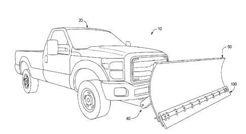
the blade of the snowplow.
[0003] To address these problems, snowplows typically include blade
assemblies that include springs that support the blade, bias the blade toward
the
travel surface, and provide for or enable upward and/or rearward movement or
pivoting of the blade when the blade encounters an uneven travel surface or
other
discontinuity.
[0004] To address these problems, known snowplow blade assemblies also
typically include a blade wear member removably attached to the bottom of the
snowplow blade. This blade wear member is configured to engage the travel
1
CA 02951910 2016-12-13
surface and configured to wear out during use. This blade wear member protects
the bottom of the blade from direct engagement with the travel surface and
thus
minimizes wear on and damage to the bottom of the blade from such engagements.
[0005] Such known snowplow blade wear members often include a straight
or flat somewhat flexible rubber wear strip configured to be attached to the
bottom
of the blade. As the bottom edge of such known blade wear members engage the
ground surface to direct the snow, the rubber blade wear members tend to
rapidly
wear. Such worn rubber blade wear members can become less efficient or
ineffective.
[0006] As the bottom edge of such known blade wear members engage the
ground surface to direct the snow, the rubber blade wear members also tend to
partially break off, fracture, chip, or become otherwise damaged when the
blade
wear members engage a discontinuity in the travel surface such as a bump,
pothole, crack, rumble strip, step, manhole, or manhole cover. Such damaged
rubber blade wear members can become less efficient or ineffective.
[0007] The quicker the blade wear member wears down or is damaged, the
more often the blade wear member needs to be replaced, and the more costly it
is
to operate the snowplow. Additionally, when a blade wear member wears down or
is
damaged, the engagement with the travel surface is less even and the
performance
of the snowplow suffers, which in turn can increase the time and expense
necessary to clear the snow from the travel surfaces.
[0008] Therefore, a need exists for better snowplow blade wear members
that provide improved engaging function between the blade and the travel
surface,
that wear down at a substantially slower rate than known snowplow blade wear
members, and that minimize the tendency of the blade wear member to partially
break off, fracture, chip, or become otherwise damaged when the blade wear
member engages a discontinuity in the travel surface.
[0009] There also exists a continuing need for uses for used tires to prevent
used tires from being disposed of in landfills.
2
CA 02951910 2016-12-13
SUMMARY
[0010] Various embodiments of the present disclosure provide a plow blade
wear member, such as a snowplow blade wear member that solves the above
problems by providing a blade wear member having a slower wear rate than known
blade wear members, and having a reduced tendency to partially break off,
fracture,
chip, or become otherwise damaged when the blade wear member engages a
discontinuity in a travel surface.
[0011] More specifically, the plow blade wear member is configured to be
removably and adjustably attached to a blade of a blade assembly that is
attached
or attachable to a vehicle. The vehicle and the blade assembly generally form
the
plow. The blade wear member, the blade assembly, and the vehicle are
configured
to operate as a snowplow, although it should be appreciated that the blade
wear
member of the present disclosure can be employed for or in conjunction with
plow
blades other than snowplow blades. Thus, the present disclosure also provides:
(a)
a plow blade assembly including the plow blade wear member (such as a snowplow
blade assembly with a snowplow blade wear member); and (b) a plow vehicle
including a plow blade assembly with the blade wear member (such as a snowplow
vehicle including a snowplow blade assembly with the snowplow blade wear
member).
[0012] This blade wear member of various embodiments of the present
disclosure includes an elongated curved or arched body having a first or top
edge, a
second or bottom edge, a third or right side edge, a fourth or left side edge,
a front
concave surface, and a rear convex surface. The blade wear member defines a
plurality of spaced apart oval attachment slots that enable the blade wear
member
to be attached to a blade in each of a plurality of different positions or
heights
relative to the blade or bottom edge of the blade.
[0013] As the blade wear member moves along a travel surface, the blade
wear member or bottom part is strong enough to not flex or bend backward
against
its natural curvature when the blade wear member, or part thereof, engages an
3
CA 02951910 2016-12-13
object or discontinuity protruding from the travel surface at a designated
force level.
However, when the blade wear member moves along a travel surface and engages
an object or discontinuity protruding from the travel surface above the
designated
force level, the blade wear member or bottom part thereof, can flex or bend
backward against its natural curvature. The natural curvature of the blade
wear
member causes the blade wear member to be biased back to or return to its
original
shape or position.
[0014] In various embodiments of the present disclosure, the blade wear
member is formed or cut from an airplane tire. In various embodiments of the
present disclosure, the blade wear member is formed or cut from a used fiber
reinforced airplane tire having a relatively large outer circumference to
provide the
desired radius of curvature, the desired thickness, and the desired strength
for the
blade wear member of the present disclosure.
[0015] Other objects, features, and advantages of the present disclosure
will be apparent from the following detailed disclosure, taken in conjunction
with the
accompanying sheets of drawings, wherein like reference numerals refer to like
parts.
4
CA 02951910 2016-12-13
BRIEF DESCRIPTION OF THE FIGURES
[0016] Fig. 1 is a front perspective view of snowplow including a truck, a
blade assembly (including a blade) attached to the truck, and a blade wear
member
of one example embodiment of the present disclosure attached to the blade.
[0017] Fig. 2 is a front perspective view of the blade wear member of Fig. 1.
[0018] Fig. 3 is a end view of the blade wear member of Fig. 1.
[0019] Fig. 4 is an exploded front perspective view of the blade wear
member of Fig. 1, an example blade wear member attachment assembly of one
embodiment of the present disclosure, and a fragmentary bottom portion of a
blade.
[0020] Fig. 5 is an assembled front perspective view of the blade wear
member of Fig. 1, the example blade wear member attachment assembly of Fig. 4,
and a fragmentary bottom portion of a blade, and showing the blade wear member
attached to the bottom of the blade in a first position.
[0021] Fig. 6 is an assembled end view of the blade wear member of Fig. 1,
the example blade wear member attachment assembly of Fig. 4, and a fragmentary
bottom portion of a blade, and showing the blade wear member attached to the
bottom of the blade in one of a plurality of different position or heights.
[0022] Fig. 7 is an assembled front perspective view of the blade wear
member of Fig. 1, the example blade wear member attachment assembly of Fig. 4,
and a fragmentary bottom portion of a blade, and showing the blade wear member
attached to the bottom of the blade in another one of the plurality of
different
positions or heights.
[0023] Fig. 8 is an exploded front perspective view of another embodiment
of the blade wear member of the present disclosure, an example blade wear
member attachment assembly of one embodiment of the present disclosure, and a
fragmentary bottom portion of a blade, wherein the blade wear member includes
two bodies.
CA 02951910 2016-12-13
DETAILED DESCRIPTION
[0024] The present disclosure solves the above problems by providing a
blade wear member having a slower wear rate than known blade wear members,
and also by providing a blade wear member having a reduced tendency to
partially
break off, fracture, chip, or become otherwise damaged when the blade wear
member engages a discontinuity in a travel surface.
[0025] Referring now to the drawings and particularly to Figs. 1, 2, 3, 4, 5,
6, and 7, the blade wear member of one example embodiment of the present
disclosure is generally illustrated and indicated by numeral 100. The
illustrated
example plow blade wear member 100 is configured to be removably and
adjustably attached to a blade 50 of a blade assembly 40 that is attached or
attachable to a vehicle 20. The vehicle 20 and the blade assembly 40 generally
form a plow 10. In this illustrated embodiment, the blade wear member 100, the
blade assembly 40, and the vehicle 20 are configured to operate as a snowplow,
although it should be appreciated that the blade wear member of the present
disclosure can be employed for or in conjunction with plow blades other than
snowplow blades.
[0026] In this illustrated example embodiment, blade wear member 100
includes an elongated curved or arched body 104 having a first or top edge
108, a
second or bottom edge 112, a third or right side edge 116, a fourth or left
side edge
120, a front concave surface 124, and a rear convex surface 128. In this
illustrated
example embodiment, the blade wear member 100 includes a single body 104;
however, it should be appreciated that the blade wear member can alternatively
include two or more bodies that co-act to form the entire blade wear member
and
that are configured to be attached to a single blade as further discussed
below with
respect to Fig. 8.
[0027] The blade wear member 100 in this illustrated example embodiment
has: (a) the first or top edge 108 extending parallel or substantially
parallel to the
second or bottom edge 112; (b) the third or right side edge 116 extending
parallel or
6
CA 02951910 2016-12-13
substantially parallel to the fourth or left side edge 120; and (c) the front
concave
surface 124 having the same or substantially the same arc or radius of
curvature as
the rear convex surface 128. In alternative embodiments of the blade wear
member
of the present disclosure: (a) the first or top edge and the second or bottom
edge
extend in intersecting planes; (b) the third or right side edge and the fourth
or left
side edge extend in intersecting planes; and/or (c) the front concave surface
and
the rear convex surface extend toward each other at the top section or the
bottom
section. The blade wear member 100 in this illustrated example embodiment has
a
substantially uniform thickness: (a) from the first or top edge 108 to the
second or
bottom edge 112; and (b) from the third or right side edge 116 to the fourth
or left
side edge 120. In alternative embodiments of the blade wear member of the
present disclosure, the blade wear member has a non-uniform thickness: (a)
from
the first or top edge 108 to the second or bottom edge 112; and/or (b) from
the third
or right side edge 116 to the fourth or left side edge 120.
[0028] This illustrated example blade wear member 100 provides a desired
curvature, thickness, and strength that are optimized for attachment to a plow
blade,
and particularly a snowplow blade. In this illustrated embodiment, the
thickness of
the blade wear member is at least approximately one inch. In this illustrated
embodiment, the radius of curvature of the blade wear member is approximately
40
inches. In this illustrated embodiment, the distance from plane A (indicated
by
dotted line in Fig. 3) to plane B (indicated by dotted line in Fig. 3) is
approximately
1.125 inches. It should be appreciated that in other embodiments of the
present
disclosure, the curvature, thickness, and strength of the plow blade wear
member
can vary.
[0029] The body 104 of this illustrated example blade wear member 100
defines a series of substantially horizontally aligned, off center,
substantially
vertically extending, spaced apart, oval attachment slots 130a, 130b, 130c,
130d,
130e, 130f, 130g, 130h, 130i, 130j, and 130k. The oval attachment slots 130a,
130b, 130c, 130d, 130e, 130f, 130g, 130h, 130i, 130j, and 130k extend though
the
entire body 104, and particularly from the front concave surface 124 to the
rear
7
CA 02951910 2016-12-13
convex surface 128. As shown in Figs. 2, 4, 5, and 7, the oval shapes of the
series
of spaced apart attachment slots 130a, 130b, 130c, 130d, 130e, 130f, 130g,
130h,
130i, 130j, and 130k enable the blade wear member 100 to be attached to a
blade
such as blade 50 at spaced apart locations along the blade 50, and in each of
a
plurality of different positions or heights relative to the blade 50 or bottom
edge of
the blade 50.
[0030] More specifically, in this illustrated embodiment, as best seen in
Figs. 1, 4, 5, 6, and 7, the present disclosure includes a blade wear member
attachment assembly including a front attachment bar 60, a rear attachment
plate
65, a blade support 70, and a plurality of fasteners (such as bolts 80a, 80b,
80c,
80d, 80e, 80f, 80g, 80h, 80i, 80j, and 80k, and nuts 90a, 90b, 90c, 90d, 90e,
90f,
90g, 90h, 90i, 90j, and 90k) configured to attach the blade wear member 100 to
the
bottom section of the blade 50. The front attachment bar 60, the rear
attachment
plate 65, the blade 50, and the blade support 70 each include or define a
corresponding series of openings such that the bolts 80a, 80b, 80c, 80d, 80e,
80f,
80g, 80h, 80i, 80j, and 80k can extend though the front attachment bar 60, the
blade wear member 100, the rear attachment plate 65, the blade 50, and the
blade
support 70, and such that the nuts 90a, 90b, 90c, 90d, 90e, 90f, 90g, 90h,
90i, 90j,
and 90k can be attached to the bolts 80a, 80b, 80c, 80d, 80e, 80f, 80g, 80h,
80i,
80j, and 80k to secure such components together as generally shown in Figs. 1,
5,
6, and 7. The blade wear member 100 is positioned or sandwiched between the
attachment bar 60 and the rear attachment plate 65 in this illustrated
embodiment.
It should be appreciated that other suitable blade wear member attachment
assemblies can be used to attach the blade wear member 100 to the blade 50 in
accordance with the present disclosure.
[0031] As mentioned above, the oval shapes of the attachment slots 130a,
130b, 130c, 130d, 130e, 130f, 130g, 130h, 130i, 130j, and 130k enable the
blade
wear member 100 to be attached to a blade at various different heights. Fig. 5
shows the blade wear member 100 attached to the blade 50 at an intermediate
position relative to the blade 50. After the bottom second edge 112 of the
blade
8
CA 02951910 2016-12-13
wear member 100 wears down a designated amount or to a designated level (as
shown in Fig. 7), the blade wear member 100 can be moved or adjusted
downwardly one or more times and eventually such that the blade wear member
100 is attached to the blade 50 at the lowest position relative to the blade
50 for the
series of attachment slots 130a, 130b, 130c, 130d, 130e, 130f, 130g, 130h,
130i,
130j, and 130k. Fig. 7 shows the blade wear member 100 attached to the blade
50
at this lowest position relative to the blade 50 for the series of attachment
slots
130a, 130b, 130c, 130d, 130e, 130f, 130g, 130h, 130i, 130j, and 130k.
[0032] In certain embodiments of the present disclosure, after the first edge
112 of the blade wear member 100 has been further worn down to a further
level,
the blade wear member 100 can detached from the blade 50, turned upside down,
and reattached to the blade 50 such that the series of attachment slots 130a,
130b,
130c, 130d, 130e, 130f, 130g, 130h, 130i, 130j, and 130k are used to attach
the
blade wear member 100 to the blade 50 in an upside down position. In other
embodiments of the present disclosure that are not shown, a second series of
horizontally aligned spaced apart attachment slots may be employed to
accomplish
the additional or alternative use or attachment.
[0033] The blade wear member 100 has a natural curvature (i.e., is curved
in the normal or resting state). Fig. 6 best illustrates the curvature of the
blade wear
member 100 relative to the blade 50 and the rear attachment plate 65. Fig. 6
also
illustrates that the bottom portion of the convex surface 128 of the curved
blade
wear member 100 is spaced apart from the rear attachment plate 65 a distance
X,
which in this illustrated example embodiment is approximately 0.25 inches at
the
lowest point of the rear attachment plate 65. Fig. 6 further shows that the
gap
between the curved blade wear member 100 and the rear attachment plate 65
narrows in an upward direction.
[0034] As the blade wear member 100 moves along a travel surface, the
blade wear member 100 or bottom part thereof is strong enough to not flex or
bend
backward against its natural curvature when the blade wear member 100 or part
thereof engages an object or discontinuity protruding from the travel surface
at a
9
CA 02951910 2016-12-13
designated force level. However, when the blade wear member 100 moves along a
travel surface and engages an object or discontinuity protruding from the
travel
surface at a force level above the designated force level, the blade wear
member
100 or bottom part thereof can flex or bend backward against its natural
curvature.
For example, the blade wear member 100 or bottom part thereof can flex or bend
backward the entire distance X which is 0.125 inches in this illustrated
example
embodiment. The natural curvature of the blade wear member 100 causes the
blade wear member 100 to be biased back to or return to its original shape or
position. The gap between the curved blade wear member 100 and the rear
attachment plate 65 facilitates this rearward bending of the bottom portion of
the
blade wear member 100 without causing damage to the blade wear member 100.
[0035] In this illustrated example embodiment, the blade 50, the front
attachment bar 60, the rear attachment plate 65, and the blade support 70, the
bolts
80a, 80b, 80c, 80d, 80e, 80f, 80g, 80h, 80i, 80j, and 80k, and the nuts 90a,
90b,
90c, 90d, 90e, 90f, 90g, 90h, 90i, 90j, and 90k, are all formed from a
suitable metal
such as steel. It should be appreciated that the blade 50, the front
attachment bar
60, the rear attachment plate 65, the blade support 70, the bolts 80a, 80b,
80c, 80d,
80e, 80f, 80g, 80h, 801, 80j, and 80k, and the nuts 90a, 90b, 90c, 90d, 90e,
90f,
90g, 90h, 901, 90j, and 90k, can be formed from other suitable materials. It
should
further be appreciated that the rear attachment plate 65 is in part used to
prevent
damage to the blade 50. If the rear attachment plate 65 is damaged, it is much
less
expensive and time consuming to replace the rear attachment plate 65 than the
blade 50.
[0036] In various embodiments of the present disclosure, the blade wear
member is formed from multiple plies of a flexible material or element, such
as
rubber, to provide enhanced wear characteristics and to have the rigidity
necessary
for engaging a travel surface.
[0037] In various embodiments of the present disclosure, each layer or ply
of the blade wear member of the present disclosure has a reinforcing material
(such
as a polymer material, a polyester material, a nylon or aliphatic or semi-
aromatic
CA 02951910 2016-12-13
polyamide material, a rayon or regenerated cellulose material, or a synthetic
material) that reinforces the flexible material of the blade wear member to
provide
greater tensile strength. The flexible material is coupled with or bonded
around each
fiber of reinforcing material in various embodiments.
[0038] In various embodiments of the present disclosure, the blade wear
member includes a plurality of layers or plies of reinforcing material
integrated within
a plurality of layers of flexible material. The quantity of reinforcing layers
may vary in
accordance with the present disclosure.
[0039] In various embodiments of the present disclosure, each layer of
reinforcing material includes one ply of fibers angled in one direction and at
least
one other ply of fibers laid on top of or adjacent to the first ply at a
substantially non-
perpendicular different angle.
[0040] In various embodiments of the present disclosure, the multiple plies
and the configuration in which the reinforcing material is positioned or
layered within
each ply causes (when the blade wear member is formed), the bottom edge or
working edge of the blade wear member to include a plurality or pattern of
indentations, serrations, or dimples. This pattern substantially decreases
wear of
the blade wear member
[0041] In various embodiments of the present disclosure, the blade wear
member is formed from a plurality of separate pieces that are attached or
otherwise
suitably joined together to form the blade wear member.
[0042] In various embodiments of the present disclosure, the blade wear
member is formed or cut from a used airplane tire.
[0043] In various embodiments, the blade wear member is formed or cut
from a used airplane tire by: (a) removing the bead of the airplane tire; (b)
trimming
the remaining portion of the airplane tire to obtain a strip from the
circumference of
the airplane tire; (c) shaving the strip to the proper thickness if necessary;
and (d)
die cutting the shaved strip to the desired specifications (such as length).
[0044] In various embodiments of the present disclosure, the blade wear
member is formed or cut from a used fiber reinforced airplane tire having an
outer
11
CA 02951910 2016-12-13
circumference of approximately 120 inches and a diameter of approximately
50 inches (such as a polymer fiber reinforced, polyester fiber reinforced,
nylon or
aliphatic or semi-aromatic polyamide fiber reinforced, rayon or regenerated
cellulose fiber reinforced, or synthetic fiber reinforced airplane tire having
an outer
circumference of approximately 120 inches and a diameter of approximately
50 inches). Such airplane tires provide the desired radius of curvature, the
desired
at least approximately one inch thickness for the blade wear member, and the
desired strength of the blade wear member. The curvature of the blade wear
member formed or cut from a used airplane tire provides a desired spring
action or
resistance that causes the blade wear member to return to its normal position
after
being engaged by a discontinuity in the travel surface above certain force
levels.
[0045] In various embodiments of the present disclosure, the blade wear
member is formed or cut from a used airplane tire in lengths from six feet up
to
fifteen feet long. In various embodiments of the present disclosure, the
aircraft tire
employed has a one inch thickness and has a four foot height. The four foot
height
tire provides the desired radius of curvature for the blade wear member as
explained above. In various embodiments of the present disclosure, the
aircraft tire
employed is up to ten feet wide.
[0046] Thus, in various embodiments of the present disclosure, the blade
wear member is formed from a vulcanized rubber that has been treated with
chemicals to improve the physical properties of the rubber and thus prevent
the
rubber from breaking down. Since the characteristics of vulcanized rubber
prevent
the rubber from being broken down and recycled similar to common plastics, the
present disclosure provides an alternative use for existing used or worn out
airplane
tires. By utilizing vulcanized airplane tire rubber, the present disclosure
provides the
additional advantage of preventing the buildup of airplane tires in landfills.
[0047] In various embodiments of the present disclosure, the blade wear
member is formed from the airplane tire by die cutting the airplane tire under
compression such that each ply and the flexible material extends further than
the
plurality of reinforcing fibers that lay within that ply and the flexible
material.
12
CA 02951910 2016-12-13
However, since the reinforcing fibers are coupled to or bonded with the
flexible
material, as the flexible material expands, the fibers will be pulled or
stretched along
with the expanding flexible material. It should be appreciated that with the
different
thicknesses of the flexible material and not a lower coefficient of expansion,
as the
reinforcing fibers are pulled, a greater proportion of the reinforcing fibers,
relative to
the overall size, are stretched to expand substantially the same distance as
the
flexible material, and when the die cuts through the reinforcing material, a
greater
length of reinforcing material than the flexible material is cut. When the
flexible
material decompresses, the stretched reinforcing fibers (that have actually
been cut
more than the rubber material) will retract a greater distance than the
flexible
material to cause a plurality of indentations, serrations or dimples. That is,
as
described above, as a greater proportion (relative to their overall size) of
the
reinforcing fibers were stretched than the flexible material and subsequently
cut
away, less of the reinforcing fibers (proportionate to overall size) remain
after the
cut. In other words, when the flexible material and the reinforcing fibers
retract to
their pre-compression state, less of the fibers will remain (in proportion to
their
overall size) and thus the fibers will retract a greater distance than the
flexible
material, leaving an uneven edge or surface for each ply of the blade wear
member.
As described above, as the fibers and flexible material are coupled or bonded
to
each other, as the fibers retract, portions of the flexible material will
retract more
than other portions revealing the dimples. The indentations are formed in the
flexible material around where the fiber has retracted.
[0048] The plurality of dimples provide a decreased amount of surface area
for the blade wear member to engage the travel surface while still performing
substantially the same function as a smooth edged blade wear member. When the
bottom or working edge engages the ground surface to push snow, only the non-
indented portion of the blade wear member edge will directly engage the ground
surface. That is, without the entire edge of the blade wear member engaging
the
ground surface, the blade wear member edge will not be worn away as quickly
and
the blade wear member will not need to be replaced as often.
13
CA 02951910 2016-12-13
[0049] In various embodiments of the present disclosure, the blade wear
member includes two or more different integrally connected sections or layers.
The
sections or layers are different in the spacing between the reinforcing fibers
in each
section or layer. In certain such embodiments, the first or inner layer
includes the
reinforcing fibers spaced relatively close together (in the direction from the
concave
front surface to the convex rear surface), and a second or outer layer
including the
reinforcing fibers spaced further apart (in the direction from the concave
front
surface to the convex rear surface).
[0050] Referring now to Fig. 8, the plow blade wear member of another
example embodiment of the present disclosure is generally illustrated and
indicated
by numeral 1100. The illustrated example plow blade wear member 1100 is
configured to be removably and adjustably attached to a blade 50 of a blade
assembly that is attached or attachable to a vehicle. In this illustrated
embodiment,
the blade wear member 1100 includes multiple elongated curved or arched bodies
1104a and 1104b. In this embodiment, body 1104a has a first or top edge, a
second or bottom edge, a third or right side edge a fourth or left side edge,
a front
concave surface, and a rear convex surface. In this embodiment, body 1104b
also
has a first or top edge, a second or bottom edge, a third or right side edge,
a fourth
or left side edge, a front concave surface, and a rear convex surface. In this
embodiment, a blade wear member attachment assembly including a front
attachment bar 1160, a rear attachment plate 1165, a blade support 1170, and a
plurality of fasteners (such as bolts 1180a, 1180b, 1180c, 1180d, 1180e,
1180g,
1180h, 11801, and 1180j, and 1180k, and nuts 1190a, 1190b, 1190c, 1190d,
1190e,
1190g, 1190h, 1190i, 1190j, and 1190k) is used to attach each of the bodies
1104a
and 1104b of the blade wear member 1100 to the blade 50. In this illustrated
example embodiment, the middle bolt and middle nut is not used. In this
embodiment, the blade wear member bodies 1104a or 1104b can be replaced if
damaged or worn without having to replace the other body. It should thus be
appreciated from this alternative embodiment that the blade wear member of the
14
CA 02951910 2016-12-13
present disclosure alternatively includes two or more bodies that form the
entire
blade wear member and that are configured to be attached to a single blade.
[0051] It should be appreciated from the above that various embodiments
of the present disclosure provide a plow blade wear member (such as a snowplow
blade wear member) that solves the above problems. It should also be
appreciated
from the above that various embodiments of the present disclosure provide a
plow
blade assembly with the plow blade wear member (such as a snowplow blade
assembly with a snowplow blade wear member). It should further be appreciated
from the above that various embodiments of the present disclosure provide a
plow
vehicle with a plow blade assembly including the blade wear member (such as a
snowplow vehicle with a snowplow blade assembly including the snowplow blade
wear member).
[0052] It will be understood that modifications and variations may be
effected without departing from the scope of the novel concepts of the present
disclosure, and it is understood that this application is to be limited only
by the
scope of the claims.