Note: Descriptions are shown in the official language in which they were submitted.
CA 02952011 2016-12-12
WO 2015/191167 PCT/US2015/027031
RETRACTABLE LEASH WITH END-OF-LEASH WARNING
[0001] This international patent application claims priority to and the
benefit of
both U.S. Patent Application Serial Number 14/302,762 filed on June 12, 2014,
and U.S.
Patent Application Serial Number 14/692,301 filed on April 21, 2015, both of
which are
incorporated herein by reference.
TECHNICAL FIELD
[0002] Embodiments of the present invention relate to leashes, tethers,
cords, or
ropes. More particularly, certain embodiments relate to a retractable dog
leash providing
an end-of-leash warning.
BACKGROUND
[0003] When walking a dog on a retractable leash, often times the dog
pulls on
the leash such that the leash becomes fully detracted from its housing,
jerking the arm of
the person walking the dog and jerking and/or choking the neck of the dog (one
end of the
leash being attached to the housing held by the person and the other end being
attached to
a collar of the dog). In such situations, neither the person walking the dog
nor the dog
may be aware that the retractable leash is about to run out. Therefore, it may
be desirable
to provide a warning to the person walking the dog and/or to the dog that the
leash is
about to run out. Furthermore, other mechanisms (for uses other than for
walking a dog)
may have a leash, cord, tether, or rope that is retractable and is coiled up
within a housing
or on a frame or reel device of some kind. It may be desirable to provide a
similar
warning in such other mechanisms as well.
[0004] Further limitations and disadvantages of conventional,
traditional, and
proposed approaches will become apparent to one of skill in the art, through
comparison
of such approaches with the subject matter of the present application as set
forth in the
remainder of the present application with reference to the drawings.
1
CA 02952011 2016-12-12
WO 2015/191167 PCT/US2015/027031
SUMMARY
[0005] One embodiment of the present invention comprises a system. The
system
includes a rotatable retracting mechanism and a leash coiled around the
rotatable
retracting mechanism and configured to be uncoiled from and recoiled to the
rotatable
retracting mechanism. The system also includes an end-of-leash detection
mechanism
configured to determine when the leash is nearing a maximum uncoiled state as
the leash
is being uncoiled. The system further includes a warning mechanism operatively
connected to the end-of-leash detection mechanism and configured to generate a
warning
signal in response to the end-of-leash detection mechanism determining when
the leash is
nearing the maximum uncoiled state. The warning signal may include one or more
of a
mechanical vibration through the leash, an emitted sonic signal, an emitted
infrared
signal, or a transmitted radio frequency signal. The emitted sonic signal may
be audible
to dogs but not to humans.
[0006] In accordance with an embodiment, the end-of-leash detection
mechanism
includes a spring component and a pressure sensor. The spring component is
configured
to apply a determined amount of pressure to the pressure sensor when the leash
is nearing
the maximum uncoiled state. The pressure sensor is configured to activate the
warning
mechanism upon sensing the determined amount of pressure. In accordance with
an
embodiment, the system includes an actuator configured to attach to a dog
collar. The
actuator is also configured to receive the warning signal and generate an
emitted sonic
signal in response to receiving the warning signal. The emitted sonic signal
may be
audible to dogs and not to humans.
[0007] In accordance with an embodiment, the end-of-leash detection
mechanism
includes a spring component and the warning mechanism includes a rattle
component
operatively connected to the spring component. The spring component is
configured to
build up stored energy as the leash uncoils in response to rotation of the
rotatable
retracting mechanism. The spring component is further configured to release
the stored
energy when the leash is nearing the maximum uncoiled state. The rattle
component is
configured to make a rattling sound in response to the stored energy being
released.
2
CA 02952011 2016-12-12
WO 2015/191167 PCT/US2015/027031
[0008] In accordance with an embodiment, the end-of-leash detection
mechanism
includes a switching mechanism and a bulb mechanism attached to the leash. The
bulb
mechanism on the leash is configured to activate the switching mechanism upon
passing
by the switching mechanism when the leash is nearing the maximum uncoiled
state. The
switching mechanism is operatively connected to the warning mechanism. The
warning
mechanism is configured to generate the warning signal in response to the
switching
mechanism being activated.
[0009] In accordance with an embodiment, the end-of-leash detection
mechanism
includes a sensing mechanism and a tag attached to the leash. The tag on the
leash is
configured to be sensed by the sensing mechanism upon passing by the sensing
mechanism when the leash is nearing the maximum uncoiled state. The tag may
include
one of a magnetic tag, an optically encoded tag, or a radio frequency
identification tag.
The sensing mechanism may include one of a magnetic sensor, an optical sensor,
or a
radio frequency identification sensor. The sensing mechanism is operatively
connected to
the warning mechanism, and the warning mechanism is configured to generate the
warning signal in response to the sensing mechanism sensing the tag.
[0010] One embodiment comprises an apparatus. The apparatus includes a
housing and a cord residing within the housing. The apparatus also includes
means for
facilitating detraction of the cord from the housing and retraction of the
cord back into the
housing. The apparatus further includes means for determining when the cord is
nearing
a maximum state of detraction from the housing, and means for generating a
warning
signal in response to determining when the cord is nearing the maximum state
of
detraction from the housing. The warning signal may include one or more of a
mechanical vibration through the cord, an emitted sonic signal, an emitted
infrared signal,
or a transmitted radio frequency signal.
[0011] One embodiment comprises a method. The method includes determining
when a leash is about to reach a maximum state of detraction from a reel
mechanism as
the leash is being detracted from the reel mechanism. The method also includes
generating a warning signal in response to determining when the leash is about
to reach
the maximum state of detraction from the reel mechanism. The warning signal
provides
an indication that the leash is about to reach the maximum state of detraction
from the
3
CA 02952011 2016-12-12
WO 2015/191167 PCT/US2015/027031
reel mechanism. The warning signal may include one or more of a mechanical
vibration
through the leash, an emitted first sonic signal, an emitted infrared signal,
or a transmitted
radio frequency signal. The method may further include transmitting at least a
portion of
the warning signal to an actuator device attached to a collar worn by a dog.
The method
may also include the actuator device generating and emitting a second sonic
signal, that is
audible to dogs and not to humans, in response to the warning signal.
[0012] These and other novel features of the subject matter of the
present
application, as well as details of illustrated embodiments thereof, will be
more fully
understood from the following description and drawings.
BRIEF DESCRIPTION OF THE DRAWINGS
[0013] Fig. 1 illustrates a problem that can occur when walking a dog;
[0014] Fig. 2 illustrates a first example embodiment of a retractable dog
leash
apparatus;
[0015] Fig. 3 illustrates a magnified view of a portion of the
retractable dog leash
apparatus of Fig. 2;
[0016] Fig. 4 illustrates a schematic block diagram of an embodiment of a
portion
of the retractable dog leash apparatus of Figs. 1-3;
[0017] Fig. 5 illustrates an example embodiment of a retractable dog
leash system
having both a retractable dog leash apparatus and an actuator;
[0018] Fig. 6 illustrates a portion of a second example embodiment of a
retractable dog leash apparatus;
[0019] Fig. 7 illustrates the functional operation of the portion of the
retractable
dog leash apparatus of Fig. 6 when a leash of the retractable dog leash
apparatus is
connected to a collar worn by a dog;
[0020] Fig. 8 illustrates a portion of a third example embodiment of a
retractable
dog leash apparatus;
[0021] Fig. 9 illustrates a portion of a fourth example embodiment of a
retractable
dog leash apparatus;
4
CA 02952011 2016-12-12
WO 2015/191167 PCT/US2015/027031
[0022] Fig. 10 illustrates the portion of the retractable dog leash
apparatus of Fig.
9 showing how a bulb mechanism interacts with a switching mechanism;
[0023] Fig. 11 illustrates a schematic block diagram of an embodiment of
a
portion of the retractable dog leash apparatus of Fig. 9 and Fig. 10;
[0024] Fig. 12 illustrates a portion of a fifth example embodiment of a
retractable
dog leash apparatus;
[0025] Fig. 13 illustrates a schematic block diagram of an embodiment of
a
portion of the retractable dog leash apparatus of Fig. 12;
[0026] Fig. 14 illustrates a portion of a sixth example embodiment of a
retractable
dog leash apparatus;
[0027] Fig. 15 illustrates the portion of the retractable dog leash
apparatus of Fig.
14 showing how a trigger component interacts with a lever mechanism which
interacts
with a toothed component;
[0028] Fig. 16 illustrates a dog owner happily walking his dog using an
embodiment of the invention of the present application; and
[0029] Fig. 17 illustrates a portion of a seventh example embodiment of a
retractable dog leash apparatus.
DETAILED DESCRIPTION
[0030] The terms "leash", "tether", "cord", and "rope" may be used
interchangeably herein. However, in general, the term "cord" is broader than
the terms
"leash", "tether", or "rope". For example, a leash may be considered a type of
cord. The
term "housing" is used broadly herein and may refer to a substantially
enclosed casing, a
substantially open frame structure, or any architecture capable of storing a
retractable
cord. The phrases "nearing a maximum state of detraction" and "nearing a
maximum
uncoiled state" may be used interchangeably herein and may refer to a cord
that is being
pulled out of a housing that is about to run out, such that it cannot be
pulled out any
further from the housing, but has not yet run out. For example, a cord that is
capable of
CA 02952011 2016-12-12
WO 2015/191167 PCT/US2015/027031
being detracted fifteen feet out of a housing may be defined as nearing a
maximum state
of detraction when thirteen feet of the cord has been detracted from the
housing.
[0031] Fig. 1 illustrates a problem that can occur when walking a dog.
When
walking a dog on a retractable leash 100, often times the dog pulls on the
leash such that
the leash becomes fully detracted from its housing, jerking the arm of the
person walking
the dog and jerking and/or choking the neck of the dog (one end of the leash
being
attached to the housing held by the person and the other end being attached to
a collar of
the dog). In such situations, neither the person walking the dog nor the dog
may be aware
that the retractable leash is about to run out. Therefore, it is desirable to
provide a
warning to the person walking the dog, and/or to the dog, that the leash is
about to run
out.
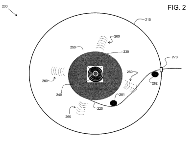
[0032] Fig. 2 illustrates a first example embodiment of a retractable dog
leash
apparatus 200. The apparatus 200 includes a housing 210, a retractable leash
220 that
may be coiled to and uncoiled from the housing 210 in a rotating manner, a
spring
component 230 (e.g., a spiral torsion spring), a pressure sensor 240, and a
warning
mechanism (e.g., a sound emitter or a radio frequency transmitter) 250
configured to emit
an audio or radio frequency signal 260. The spring component 230 and the
pressure
sensor 240 constitute an end-of-leash detection mechanism as discussed in more
detail
later herein. The leash 220 may exit from the housing and retract back into
the housing
via a port 270 along roller guides 281 and 282, for example.
[0033] Fig. 3 illustrates a magnified view of a portion of the
retractable dog leash
apparatus 200 of Fig. 2. In accordance with an embodiment, as the leash 220 is
detracted
from the housing 210 in a rotating manner, the spring component 230 tightens
around the
pressure sensor 240 due to the rotation. At a certain point (the end-of-leash
warning
point), the spring component 230 applies enough pressure to the pressure
sensor 240
causing the pressure sensor 240 to output an activating signal to the warning
mechanism
250. The activating signal causes the warning mechanism 250 to activate,
generating and
emitting a sound (or generating and transmitting a radio frequency signal, in
accordance
with an alternative embodiment).
[0034] The apparatus 200 is designed such that the end-of-leash warning
point
(EOLWP) corresponds to the point where the leash 220 is mostly detracted from
the
6
CA 02952011 2016-12-12
WO 2015/191167 PCT/US2015/027031
housing 210 and is about to run out. That is, the leash 220 is nearing a
maximum state of
detraction (e.g., nearing a maximum uncoiled state) from the housing 210. For
example,
a leash that is capable of being detracted twenty feet out of a housing may be
designed as
nearing a maximum state of detraction when fifteen feet of the leash has been
detracted
from the housing.
[0035] When the warning mechanism 250 emits the sound, the emitted sound
260
alerts the dog at the other end of the leash that the leash is about to run
out. As a result,
the dog becomes trained to associate the emitted sound with the leash nearing
a maximum
state of detraction. When the dog is trained (e.g., after several walks with
the owner
using the apparatus 200), the dog will learn to stop or back off from pulling
on the leash
when hearing the emitted sound. In this manner, the leash will not totally run
out and the
arm of the person walking the dog will not be jerked (and the neck of the dog
will not be
jerked or choked).
[0036] In accordance with an embodiment, the emitted sound 260 may be
audible
to both the person walking the dog (a human) and the dog itself In accordance
with
another embodiment, the emitted sound 260 may be audible to the dog but not
the human.
The warning mechanism 250 may be designed to emit a sound that is annoying to
the
dog, thus making it more likely that the dog will be trained more quickly to
stop or back
off from pulling on the leash.
[0037] Fig. 4 illustrates a schematic block diagram of an embodiment of a
portion
of the retractable dog leash apparatus 200 of Figs. 1-3. The pressure sensor
240 is
operatively connected to the warning mechanism 250 such that the pressure
sensor 240
outputs an activating signal 410 (e.g., an electrical signal) to the warning
mechanism 250
when the leash 220 is nearing a defined maximum state of detraction. The
pressure
sensor 240 acts as a transducer and generates the activating signal 410 when a
certain
amount of pressure (e.g., a force) is imposed by the spring component 230 on
the pressure
sensor 240. The pressure sensor 240 may employ any of a number of pressure-
sensing or
force-sensing technologies including but not limited to piezoresistive,
piezoelectric,
capacitive, optical, and electromagnetic.
[0038] In accordance with an embodiment, the warning mechanism 250 may
include a sound emitter. For example, the activating signal 410 may trigger a
sonic
7
CA 02952011 2016-12-12
WO 2015/191167 PCT/US2015/027031
oscillator to activate within the sound emitter. The sonic oscillator may
produce a
frequency that is audible to both humans and dogs, or just dogs. The sound
emitter may
include a power source (e.g., a small battery) to power the oscillator. In
accordance with
an embodiment, the power source may be kept charged by an energy harvesting
device
that harvests mechanical energy from the rotating motion of the apparatus, as
the leash is
uncoiled and recoiled, and converts the mechanical energy to electrical energy
which is
stored in the power source (e.g., a small battery).
[0039] In accordance with another embodiment, the warning mechanism 250
may
include a radio frequency transmitter. For example, the activating signal 410
may trigger
a radio frequency oscillator to activate within the radio frequency
transmitter. The radio
frequency oscillator may produce an electromagnetic wave 510 (see Fig. 5) that
propagates away from the apparatus 200 at a radio frequency that is capable of
being
received by an actuator 520 attached to a collar 530 of the dog being walked.
The radio
frequency transmitter may include a power source (e.g., a small battery) to
power the
oscillator.
[0040] Fig. 5 illustrates an example embodiment of a retractable dog
leash system
500 having both the retractable dog leash apparatus 200 and the actuator 520.
When the
leash 220 is nearing the defined maximum state of detraction (i.e., the
EOLWP), the radio
frequency signal 510 is transmitted by the warning mechanism 250 and received
by the
actuator 520. The received radio frequency signal 510 activates the actuator
520, causing
the actuator to emit a sonic signal 540 that is audible to the dog, which
alerts the dog at
the other end of the leash that the leash is about to run out. The actuator
520 may include
a power source (e.g., a small battery) to power the actuator.
[0041] In accordance with yet another embodiment, the warning mechanism
250
may include an ultrasonic transmitter instead of a radio frequency
transmitter. The
resulting system would work much the same way as the system 500 of Fig. 5,
except that
the actuator would be sensitive to an ultrasonic signal that is emitted by the
ultrasonic
transmitter when the leash 220 is nearing the defined maximum state of
detraction.
[0042] In accordance with still another embodiment, the warning mechanism
250
may include an infrared emitter instead of a radio frequency or ultrasonic
transmitter.
The resulting system would work much the same way as the system 500 of Fig. 5,
except
8
CA 02952011 2016-12-12
WO 2015/191167 PCT/US2015/027031
that the actuator would be sensitive to an infrared signal that is emitted by
the infrared
emitter when the leash 220 is nearing the defined maximum state of detraction.
[0043] In yet another embodiment, the actuator may be configured to apply
a
stimulus (including e.g., an electrical shock, a prick, and other stimuli) to
the dog upon
receiving an activating signal. The activating signal may be transmitted
wirelessly to the
actuator, or via wired means through the leash 220, for example, in accordance
with
various embodiments.
[0044] Fig. 6 illustrates a portion of a second example embodiment of a
retractable dog leash apparatus 600. The leash apparatus 600 is similar to the
leash
apparatus 200 of Fig. 2 except that the leash apparatus 600 does not include a
pressure
sensor or a sonic, radio frequency, or infrared emitter of any kind. In the
embodiment of
Fig. 6, the spring component 230 (e.g., a spiral torsion spring) builds up
stored energy due
to rotation as the leash 220 is detracted from the housing 210. Once the EOLWP
is
reached (i.e., when the leash 220 is nearing the defined maximum state of
detraction), the
spring component releases the stored energy causing a mechanical vibration 610
to be
propagated through the leash 220. The spring mechanism 230 is configured to
temporarily decouple from the rotating mechanism of the apparatus 600 to
release its
energy upon reaching the EOLWP.
[0045] Fig. 7 illustrates the functional operation of the portion of the
retractable
dog leash apparatus 600 of Fig. 6 when a leash 220 of the retractable dog
leash apparatus
600 is connected to a collar 530 worn by a dog. The mechanical vibration 610
propagated through the leash 220 is felt by the dog, providing an indication
to the dog
that the leash 220 is nearing the defined maximum state of detraction, causing
the dog to
stop or back off from pulling on the leash. Again, after several walks with
the dog using
the apparatus 600, the dog will train and react to the mechanical vibration in
the leash to
avoid being jerked and/or choked by the leash running out. Such an embodiment
is
purely mechanical and does not require any electrical components or sources of
electrical
power.
[0046] Fig. 8 illustrates a portion of a third example embodiment of a
retractable
dog leash apparatus 800. The leash apparatus 800 is similar to the leash
apparatus 600 of
Fig. 6 except that the leash apparatus 800 does not propagate a mechanical
vibration
9
CA 02952011 2016-12-12
WO 2015/191167 PCT/US2015/027031
through the leash 220. Instead, the leash apparatus 800 includes a rattle
component 810
operatively connected to the spring component 230. In the embodiment of Fig.
8, the
spring component 230 (e.g., a spiral torsion spring) builds up stored energy
due to
rotation as the leash 220 is detracted from the housing 210. Once the EOLWP is
reached
(i.e., when the leash 220 is nearing the defined maximum state of detraction),
the spring
component 230 releases the stored energy causing the rattle component 810 to
make a
rattling sound 820 in response to the stored energy being released. The spring
mechanism
230 is configured to temporarily decouple from the rotating mechanism of the
apparatus
600 to release its energy upon reaching the EOLWP.
[0047] The rattling sound 820 is heard by the dog, providing an
indication to the
dog that the leash 220 is nearing the defined maximum state of detraction,
causing the
dog to stop or back off from pulling on the leash. Again, after several walks
with the dog
using the apparatus 800, the dog will train and react to the rattling sound
820 to avoid
being jerked and/or choked by the leash running out. Such an embodiment is
purely
mechanical and does not require any electrical components or sources of
electrical power.
[0048] Fig. 17 depicts an alternate embodiment of a retractable dog leash
apparatus 1700. The apparatus 1700 includes a leash 1730 with a secondary
portion 1710.
When the leash 1730 is nearing the defined maximum state of detraction, the
secondary
portion 1710 of the leash 1730 will come into contact with one or more roller
guides 281
and 282 thereby forming a friction component. The secondary portion 1710 may
include a
beaded length or cable, ball-link or ball-chain, ellipse, diamond, zig-zag, or
other types of
configurations that will allow the secondary portion 1710 to form a friction
component
with roller guides 281 and 282. The friction component may produce a
frictional sound
and/or vibration 1720. Such a frictional sound and/or vibration 1720 may be
produced as
the leash 1730 nears any state of detraction including, but not limited to,
fifty (50%)
percent, seventy-five (75%) percent, or ninety (90%) percent. The frictional
sound and/or
vibration 1720 may be felt and/or heard by a person holding the leash
apparatus 1700, the
dog, or both. The frictional sound and/or vibration 1720 will not only alert
the person that
the leash 1730 is nearing the defined maximum state of detraction, but it will
also alert
the dog, which may cause the dog to stop or back off from pulling the leash
1730. After
several walks with the dog using the apparatus 1700, the dog will train and
react to the
CA 02952011 2016-12-12
WO 2015/191167 PCT/US2015/027031
frictional sound and/or vibration 1720 to avoid being jerked and/or choked by
the leash
1730 running out. While four roller guides 281 and 282 are shown in Fig. 17,
it is to be
understood that any number of roller guides in any number of arrangements may
be
included within the leash apparatus 1700, including, but not limited to,
inside or adjacent
to the port 270.
[0049] Fig. 9 illustrates a portion of a fourth example embodiment of a
retractable
dog leash apparatus 900. The apparatus 900 includes a switching mechanism 910
operatively connected to a warning mechanism 250. Again the warning mechanism
250
may emit a sonic signal, an ultrasonic signal, a radio frequency signal, or an
infrared
signal, for example, as previously described herein, in response to an
activation signal
from the switching mechanism 910. The switching mechanism 910 may be a
pressure
sensitive switching mechanism, a toggle switching mechanism, or some other
kind of
switching mechanism, in accordance with various embodiments. The apparatus 900
also
includes a bulb mechanism 920 operatively attached to the leash 220. The bulb
mechanism 920 may be a plastic knob or clasp, for example. The attachment of
the bulb
mechanism 920 to the leash 220 defines a EOLWP. When the leash 220 is being
uncoiled (see direction of uncoiling leash in Fig. 9) due to, for example, a
dog pulling on
the far end of the leash, the bulb mechanism 920 on the leash 220 will
eventually reach
the switching mechanism 910 as shown in Fig. 10.
[0050] Fig. 10 illustrates the portion of the retractable dog leash
apparatus 900 of
Fig. 9 showing how the bulb mechanism 920 interacts with the switching
mechanism 910.
The bulb mechanism 920 and the switching mechanism 910 are configured such
that the
bulb mechanism 920 triggers the switching mechanism 910 when passing by the
switching mechanism 910. When the bulb mechanism 920 reaches the switching
mechanism 910 and triggers the switching mechanism 910, the switching
mechanism 910
sends an activation signal to the warning mechanism 250. The warning mechanism
250
may act in accordance with previous descriptions of the warning mechanism 250
herein,
providing an indication to the dog and/or the human that the leash is about to
run out.
[0051] In accordance with an embodiment, when the leash 220 is retracted
such
that the bulb mechanism 920 passes by the switching mechanism 910 again, but
in the
opposite direction, the switching mechanism 910 is reset (e.g., toggled back
to its original
11
CA 02952011 2016-12-12
WO 2015/191167 PCT/US2015/027031
position) and the warning mechanism 250 is deactivated. In other embodiments,
the
warning mechanism 250 may be active for a defined period of time, after which
the
warning mechanism 250 automatically turns off, and the switching mechanism 910
may
automatically reset.
[0052] Fig. 11 illustrates a schematic block diagram of an embodiment of
a
portion of the retractable dog leash apparatus 900 of Fig. 9 and Fig. 10. The
switching
mechanism 910 is operatively connected to the warning mechanism 250 such that
the
switching mechanism 910 outputs an activating signal 1110 (e.g., an electrical
signal) to
the warning mechanism 250 when the leash 220 is nearing a defined maximum
state of
detraction (i.e., when the bulb mechanism 920 passes by). The warning
mechanism 250
may output, for example, a sonic signal, a radio frequency signal, or an
infrared signal, as
previously described herein. The sonic signal may be audible to only humans,
only dogs,
or to both humans and dogs. Alternatively the sonic signal may be an
ultrasonic signal
used to activate an actuator 520 on a collar 530 of a dog, as previously
described herein.
Similarly, the radio frequency signal or the infrared signal may be used to
activate an
actuator 520 on a collar 530 of a dog, as previously described herein.
[0053] Fig. 12 illustrates a portion of a fifth example embodiment of a
retractable
dog leash apparatus 1200. The apparatus 1200 includes a sensing mechanism 1210
operatively connected to a warning mechanism 250. Again the warning mechanism
250
may emit a sonic signal, an ultrasonic signal, a radio frequency signal, or an
infrared
signal, for example, as previously described herein, in response to an
activation signal
from the sensing mechanism 1210. The sensing mechanism 1210 may be a magnetic
sensor, an optical sensor, a radio frequency identification (RFID) sensor, or
some other
kind of sensing mechanism, in accordance with various embodiments. Further,
the
sensing mechanism may be unrelated to pressure. For example, an optical sensor
may
measure the length of leash 220 that has exited the housing 210. Further, the
length of
leash 220 may be measured using markings, symbols, colors or various textures
such as
cross-hatching on the leash 220 to signify different portions of the leash
220.
Additionally, an optical sensor may measure the length of the leash 220 that
has exited
the housing 210 through magnetic or electrically conductive materials either
on or in the
leash 220 in order to indicate the position of the leash 220 with respect to
the housing
12
CA 02952011 2016-12-12
WO 2015/191167 PCT/US2015/027031
210. The apparatus 1200 also includes a tag 1220 operatively attached to the
leash 220.
The tag 1220 may be a magnetic tag, an optically encoded tag, an RFID tag, or
some
other type of tag, in accordance with various embodiments, where the tag 1220
is
compatible with the sensing mechanism 1210. The attachment of the tag 1220 to
the
leash 220 defines a EOLWP. The tag 1220 may be attached to the leash in any of
a
number of ways including, but not limited to, glueing, sewing, riveting, etc.
Alternatively, in some embodiments, the tag may be embedded in the leash or be
an
integral part of the leash.
[0054] When the leash 220 is being uncoiled (see direction of uncoiling
leash in
Fig. 12) due to, for example, a dog pulling on the far end of the leash, the
tag 1220 on the
leash 220 will eventually reach the sensing mechanism 1210 as shown in Fig.
12. Fig. 12
shows how the tag 1220 interacts with the sensing mechanism 1210. The tag 1220
and
the sensing mechanism 1210 are configured such that the sensing mechanism 1210
senses
the tag 1220 when the tag 1220 passes by the sensing mechanism 1210. When the
tag
1220 reaches the sensing mechanism 1210 and the tag 1220 is sensed, the
sensing
mechanism 1210 sends an activation signal to the warning mechanism 250. The
warning
mechanism 250 may act in accordance with previous descriptions of the warning
mechanism 250 herein, providing an indication to the dog and/or the human that
the leash
is about to run out.
[0055] In accordance with an embodiment, when the leash 220 is retracted
such
that the tag 1220 passes by the sensing mechanism 1210 again, but in the
opposite
direction, the sensing mechanism 1210 senses the tag 1220 again and
deactivates the
warning mechanism 250. In other embodiments, the warning mechanism 250 may be
active for a defined period of time, after which the warning mechanism 250
automatically
turns off
[0056] Fig. 13 illustrates a schematic block diagram of an embodiment of
a
portion of the retractable dog leash apparatus 1200 of Fig. 12. The sensing
mechanism
1210 is operatively connected to the warning mechanism 250 such that the
sensing
mechanism 1210 outputs an activating signal 1310 (e.g., an electrical signal)
to the
warning mechanism 250 when the leash 220 is nearing a defined maximum state of
detraction (i.e., when the tag 1220 passes by). The warning mechanism 250 may
output,
13
CA 02952011 2016-12-12
WO 2015/191167 PCT/US2015/027031
for example, a sonic signal, a radio frequency signal, or an infrared signal,
as previously
described herein. The sonic signal may be audible to only humans, only dogs,
or to both
humans and dogs. Alternatively the sonic signal may be an ultrasonic signal
used to
activate an actuator 520 on a collar 530 of a dog, as previously described
herein.
Similarly, the radio frequency signal or the infrared signal may be used to
activate an
actuator 520 on a collar 530 of a dog, as previously described herein.
[0057] Fig. 14 illustrates a portion of a sixth example embodiment of a
retractable
dog leash apparatus 1400. The retractable dog leash apparatus 1400 is similar
to the
retractable dog leash apparatus 600 of Fig. 6 except that, instead of having a
spring
component 230, the apparatus 1400 includes a toothed component 1410, a lever
mechanism 1420, and a trigger component 1430. The toothed component 1410 is
configured to rotate as the leash 220 is detracted from the housing 210. The
trigger
component 1430 is attached to the leash 220 defining an EOLWP. The lever
mechanism
1420 has a first arm 1421 and a second arm 1422 attached to a pivot point
1423. The
trigger component 1430 may be a simple plastic triangular piece attached to
the leash
220.
[0058] During operation, when the leash 220 is initially being detracted
from the
housing 210, the lever mechanism 1420 is disengaged from the toothed component
1410.
However, as the EOLWP point is reached, the trigger component 1430 engages the
second arm 1422 of the lever mechanism 1420, causing the lever mechanism 1420
to
rotate around the pivot point 1423 such that the first arm 1421 engages the
toothed
component 1410. Fig. 15 illustrates the portion of the retractable dog leash
apparatus
1400 of Fig. 14 showing how the trigger component 1430 interacts with the
second arm
1422 of the lever mechanism 1420 as it passes by during detraction, and how
the first arm
1421 of the lever mechanism 1420 engages the rotating toothed component 1410.
[0059] In one embodiment, when the first arm 1421 engages the rotating
toothed
component 1410, the engagement causes the toothed component 1410 to vibrate,
causing
a mechanical vibration to be propagated through the leash 220 in a similar
manner to that
of Fig. 6 and Fig. 7. The mechanical vibration propagated through the leash
220 is felt by
the dog, providing an indication to the dog that the leash 220 is nearing the
defined
14
CA 02952011 2016-12-12
WO 2015/191167 PCT/US2015/027031
maximum state of detraction, causing the dog to stop or back off from pulling
on the
leash.
[0060] In another embodiment, when the first arm 1421 engages the
rotating
toothed component 1410, the engagement causes a clicking sound that can be
heard by
the dog. The clicking sound provides an indication to the dog that the leash
220 is
nearing the defined maximum state of detraction, causing the dog to stop or
back off from
pulling on the leash.
[0061] Further embodiments of the invention of the present application
may
include audible speakers which may be located either in the collar, in the
leash, in the
housing 210, or at an external location of any of the components previously
described in
the specification. Further, an alarm may be included, which would allow a user
to pick an
audible sound from a variety of options. For example, a user may choose to
pick a sound
that the dog may acknowledge or other sounds with which the dog is familiar,
including,
but not limited to, the sound of an electric and/or invisible fence, or any
other
recognizable sound.
[0062] Still further embodiments of the invention of the present
application may
include wired embodiments allowing communication with any electronics that may
be
located either internally or externally on the dog' s collar. In such
embodiments, a wire is
attached either inside or outside of the leash 220, which communicates either
directly
with an electronic located either internally or externally on the dog's
collar.
[0063] The various embodiments described herein are examples of possible
embodiments but are not meant to be limiting. Other embodiments falling within
the
scope of the appended claims are possible as well. For example, various other
combinations of parts of the various embodiments described herein may be
possible and
fall within the scope of the appended claims. For example, in other
embodiments, the
configuration of the lever mechanism 1420 and the trigger component 1430 may
be used
to activate switches and/or electronics.
[0064] Fig. 16 illustrates a dog owner happily walking his dog using an
embodiment of the invention of the present application. The dog is trained to
respond to
CA 02952011 2016-12-12
WO 2015/191167 PCT/US2015/027031
the warning signal by stopping or backing off from pulling on the leash so as
not to jerk
the arm of the dog owner or jerk and/or choke the neck of the dog.
[0065] In summary, an apparatus, a system, and a method for providing an
end-
of-leash warning are disclosed. Embodiments provide for determining when a
retractable leash is about to reach a maximum state of detraction from a
housing or reel
mechanism as the leash is being detracted (e.g., by a dog), and generating a
warning
signal in response to determining when the retractable leash is about to reach
the
maximum state of detraction. The warning signal may be in the form of, for
example, an
emitted sonic signal, an emitted infrared signal, a transmitted radio
frequency signal, or a
mechanical vibration through the leash. The warning signal may be used to
alert, for
example, a dog and/or a person walking a dog that the leash is running out.
[0066] In the specification and claims, reference will be made to a
number of
terms that have the following meanings. The singular forms "a", "an" and "the"
include
plural referents unless the context clearly dictates otherwise. Approximating
language, as
used herein throughout the specification and claims, may be applied to modify
any
quantitative representation that could permissibly vary without resulting in a
change in
the basic function to which it is related. Accordingly, a value modified by a
term such as
"about" is not to be limited to the precise value specified. In some
instances, the
approximating language may correspond to the precision of an instrument for
measuring
the value. Similarly, "free" may be used in combination with a term, and may
include an
insubstantial number, or trace amounts, while still being considered free of
the modified
term. Moreover, unless specifically stated otherwise, any use of the terms
"first,"
"second," etc., do not denote any order or importance, but rather the terms
"first,"
"second," etc., are used to distinguish one element from another.
[0067] As used herein, the terms "may" and "may be" indicate a
possibility of an
occurrence within a set of circumstances; a possession of a specified
property,
characteristic or function; and/or qualify another verb by expressing one or
more of an
ability, capability, or possibility associated with the qualified verb.
Accordingly, usage of
"may" and "may be" indicates that a modified term is apparently appropriate,
capable, or
suitable for an indicated capacity, function, or usage, while taking into
account that in
some circumstances the modified term may sometimes not be appropriate,
capable, or
16
CA 02952011 2016-12-12
WO 2015/191167 PCT/US2015/027031
suitable. For example, in some circumstances an event or capacity can be
expected, while
in other circumstances the event or capacity cannot occur ¨ this distinction
is captured by
the terms "may" and "may be."
[0068] This written description uses examples to disclose the invention,
including
the best mode, and also to enable one of ordinary skill in the art to practice
the invention,
including making and using any devices or systems and performing any
incorporated
methods. The patentable scope of the invention is defined by the claims, and
may include
other examples that occur to one of ordinary skill in the art. Such other
examples are
intended to be within the scope of the claims if they have structural elements
that do not
differ from the literal language of the claims, or if they include equivalent
structural
elements with insubstantial differences from the literal language of the
claims.
[0069] While the claimed subject matter of the present application has
been
described with reference to certain embodiments, it will be understood by
those skilled in
the art that various changes may be made and equivalents may be substituted
without
departing from the scope of the claimed subject matter. In addition, many
modifications
may be made to adapt a particular situation or material to the teachings of
the claimed
subject matter without departing from its scope. Therefore, it is intended
that the claimed
subject matter not be limited to the particular embodiments disclosed, but
that the claimed
subject matter will include all embodiments falling within the scope of the
appended
claims.
17