Note: Descriptions are shown in the official language in which they were submitted.
BIS133054-Foreign Countries CA 02952110 2016-12-13
- 1 -
Reaction chamber for a chemical reactor, and chemical reactor constructed
therefrom
The work which led to this invention was funded in accordance with the grant
agreement No. 246461
in the course of the seventh framework program of the European Union (FP7/2007-
2013).
The present invention relates to a reaction chamber for a chemical reactor,
comprising a casing of the
reaction chamber, a floor of the reaction chamber having an opening located in
the floor and an agitator
shaft located in the chamber and having at least one agitator element,
connected thereto. The invention
further relates to a chemical reactor which comprises a multiplicity of
reaction chambers according to
the invention, and also a process for carrying out chemical reactions in such
a reactor.
For many chemical apparatuses, it is advantageous to combine a good mixing
with a narrow residence
time distribution in a continuous mode of operation. Advantages of the good
mixing are, for example,
the reduction of mass transfer resistances, a more rapid homogenization or the
suspension of solids.
A narrow residence time distribution frequently permits a higher product
quality and a higher space-
time yield. The advantages of a continuous mode of operation include, inter
alia, stabilization of
product quality, higher resource efficiency, shorter set-up times, a higher
degree of automation and
lower hold-up volumes.
Possible applications to which said requirement profile can apply are
continuous processing of single-
or multiphase liquids, dispersions, gas-liquid mixtures, supercritical fluids
or mixtures of said materials
in various process engineering apparatuses such as chemical or biological
reactors, and also
apparatuses for absorption, extraction or crystallization.
In many chemical processes, in addition, the achievable heat exchange is a
parameter to be taken into
account. Microstructured apparatuses here offer the possibility of achieving
very high specific heat
exchange surface areas. On account of the low volume thereof, however, they
are not suitable for
reactions having a long residence time if a certain throughput is to be
achieved. In addition, the risk of
fouling and blocking due to solids present in the process on account of the
small channel diameter is a
great challenge.
Since solids, e.g. in the form of a heterogeneous catalyst, or insoluble
reaction products, are present in
many process engineering processes as wanted or unwanted components, the
handling of suspended
solids can be an additional requirement of the process equipment.
BTS133054-Foreign Countries
CA 02952110 2016-12-13
- 2 -
In practice, the defined requirement profile can most easily be achieved by a
cascade of series-
connected, continuously operated stirred tanks. Under certain conditions,
however, a more compact
structure of the apparatus may be necessary. Such an application case is,
e.g., installation into compact,
modular production plants.
It is further known that the defined requirement profile can also be met in
particular applications by
subdividing a flow tube into a plurality of compartments, each of which are
mixed by suitable agitators
and are connected to one another via openings.
However, the performance ability of such an apparatus depends greatly on the
operating conditions. A
high agitator rotary speed, long residence times and large openings between
the individual
compartments lead to a higher degree of back-mixing and therefore to a wider
residence time
distribution (e.g. L. Zhang, Q. Pan, G.L. Rempel, Residence Time Distribution
in a Multistage Agitated
Contactor with Newtonian Fluids: CFD Prediction and Experimental Validation:
Industrial &
Engineering Chemistry Research, Ind. Eng. Chem. Res. 46 2007, 3538-3546.).
Such apparatuses are widely used, especially in extraction technology. In
theory, the back mixing can
be minimized by using very small openings between adjoining compartments.
However, in this case
the pressure drop in the apparatus increases and the discharge of solids is no
longer possible, and so
this measure is frequently unsuitable for practical use.
The usc of a cascaded tube in the reaction technique is described, for
example, in US 4,370,470 (DE 32
13 628 Al). The subject matter is a contact device which is a vertical long
cylindrical housing having
closed ends that is subdivided into a plurality of individual chambers by
horizontal baffle plates and
having access from one chamber to another via concentric circular openings
that are axially centered in
the baffle walls, having a continuously rotatable shaft that extends
concentrically to the baffle walls
within the housing, having at least one agitator appliance that is fixed to
the shaft in each chamber,
wherein the shaft in the circular openings forms ring-shaped openings in the
baffle walls, in such a
manner that the ratio of the back-flow extent to the feed extent through the
openings is less than 1.5. A
description is also given of a process for the continuous preparation of
arylene sulfide polymers, in
which reaction components that are suitable for the preparation of
poly(arylene sulfide) are fed into at
least one first chamber of the above described contact vessel, as a result of
which a reaction mixture is
formed that is conducted through the chambers of the contact device, while
each chamber is
maintained under conditions for the formation of arylene sulfide polymers, and
arylene sulfide polymer
is obtained from a chamber that is situated remote from the chamber into which
the starting reaction
components are introduced. The achievable degree of backmixing in such
apparatuses is frequently too
BTS133054-Foreign Countries
CA 02952110 2016-12-13
- 3 -
high for applications that require a very narrow residence time distribution;
in particular, if the reactor
volume is low (some liters or less) and the implemcntable number of stages is
therefore restricted.
WO 2006/126891 (EP 1 904 225) discloses, for example, a cylindrical reactor
for the continuous
treatment of a stirred material composition that comprises at least two
components, comprising a
number of reactor chambers that are arranged in a primarily vertical column,
separated by base plates,
while the transport of the material composition from any desired reactor
chamber in the steady state is
arranged in order to proceed to the adjoining chamber below, wherein each
reactor chamber is provided
with a vane mechanism. The vane mechanism comprises a ring-shaped member that
is concentric to
the reactor chamber and has a vertical elongation and at least one movable
agitator member that is
arranged in order to induce a vertical movement component in the material in
the chamber. The
transport is arranged from one chamber to the next chamber in order to take
place periodically through
an opening having a slider flap in the base plate of each chamber. However,
such an apparatus has the
disadvantage that an additional movable part and, in association therewith, a
seal also, needs to be
provided at each chamber.
Cascaded tube installations having elongated gaps for decreasing the
backmixing are described in the
following publications: J. R. Couper. Chemical process equipment: Selection
and design, 2nd ed..
Elsevier, Amsterdam, Boston, 2005_ pp. 307-315 and B. C. Xu, W. R. Penney, J.
B. Fasano, Interstage
Backmixing for Single-Phase Systems in Compartmented, Agitated Columns: Design
Correlations.
Ind. Eng. Chem. Res. 44 (2005) 6103-6109.
For abrasive systems in particular, it is desirable to provide a more robust
solution in terms of
apparatus of the described formulation of the problem. In addition, it is
desirable to make the apparatus
design as flexible as possible in such a manner that use is possible with
differing systems and under
differing process conditions. In this case, the flexibility term comprises not
only the property of
changing the total volume of the reactor in a flexible manner, but also
exchanging individual elements
such as agitators or baffles to optimize the geometry for a particular
application.
The object of the present invention is to provide an apparatus which combines
said requirements.
Preferably, said apparatus in addition provides a specific heat-exchange
surface area which is as high
as possible.
According to the invention, this object is achieved by a reaction chamber for
a chemical reactor,
comprising a casing of the reaction chamber, a floor of the reaction chamber
having an opening located
in the floor, and an agitator shaft located in the chamber and having at least
one agitator element,
BTS133054-Foreign Countries
CA 02952110 2016-12-13
- 4 -
connected thereto, wherein the agitator shaft, seen in the longitudinal
direction, has a beginning and an
end. In addition in the opening of the floor a removable sleeve is provided,
which projects out of the
reaction chamber, the sleeve is arranged in alignment with the axis of
rotation of the agitator shaft, the
internal diameter of the sleeve is greater than the diameter of the agitator
shaft and the agitator shaft, at
the beginning thereof and/or at the end thereof, is adapted to absorb
reversibly a torque provided by
means of a further shaft and/or to transmit a torque to a further shaft.
By means of a multiplicity of reaction chambers according to the invention, a
chemical reactor can be
built up in a modular manner and be flexibly adapted to changing requirements.
The reaction chamber
according to the invention can of course be used not only for chemical
reactions in the narrow sense,
but also for example for extractions and the like.
The "casing of the reaction chamber" is that part of the reactor chamber
which, in the case of a vertical
reaction chamber, is the lateral boundary of the chamber interior to the
outside world. In the case of a
cylindrical or cylinder-like reaction chamber, it is then the cylinder casing.
Accordingly, the "floor of
the reaction chamber" is the lower boundary, seen in the vertical direction,
of the chamber interior to
I 5 the outside world.
Following the concept of modular usability, in the reaction chamber there is
already one agitator shaft
having at least one agitator element, connected thereto, to agitate the
contents of the reaction chamber.
Both radially and tangentially demanding agitation elements can be used. The
agitating elements can
also be made to be detachable from the agitator shaft and therefore
exchangeable.
Furthermore, additional internals can be present in the reaction chamber.
These meet two main
purposes. Firstly, they serve as baffles and prevent the co-rotation of the
liquid in the apparatus and
support an intensive mixing, secondly, they support an axial and radial
bearing mounting of the agitator
shaft. Owing to the modular structure, the rapid adaptation to various
material systems is realizable.
For example, in a system of relatively high viscosity, without great
expenditure. the baffles can be
adapted and anchor agitators can be used.
A fixed upper boundary of the chamber interior to the outside world, also
understood as a "lid", is not
absolutely necessary for the reaction chamber according to the invention. This
is because a plurality of
reaction chambers can be stacked one above the other (and are intended to be,
in order to form the
further chemical reactor according to the invention that is described
hereinafter) and the floor of the
one reaction chamber can act as a lid of the chamber lying therebeneath.
BTS133054-Foreign Countries
CA 02952110 2016-12-13
- 5 -
The floor of the reaction chamber according to the invention in addition has
an opening. Through this
opening, agitator shafts can be conducted out of the interior of the reaction
chamber and in addition
substances can be introduced into the chamber or discharged from the chamber.
At the beginning
and/or the end of the agitator shaft, said agitator shaft is designed to
absorb or transmit a torque.
Preferably it is a redetachable shape-fit connection. This can be implemented,
for example, using a
simple push-fit connection such as a hexagon. In this manner, in the case of
reaction chambers
according to the invention that arc stacked one above the other, a shared
agitator shaft can be provided
for all reaction chambers.
The reaction chamber according to the invention in addition has a detachable
sleeve, which is arranged
in the opening of the floor. In the geometric aspect, the sleeve (and
therefore also the opening of the
floor of the reaction chamber) are arranged in alignment with the axis of
rotation of the agitator shaft,
in order that, in the case of the abovementioned reaction chambers stacked one
above the other, a
continuous agitator shaft can be obtained.
Furthermore, the internal diameter of the sleeve is greater than the diameter
of the agitator shaft (of
course, agitator elements mounted on the agitator shaft are not taken into
account when the diameter is
determined). Then, even when an agitator shaft is conducted through the
opening and sleeve, a mass
transfer can take place between chambers stacked one above the other.
Preferably, the difference
between the internal diameter of the sleeve and the diameter of the agitator
shaft is > 0 mm to
< 10 mm, more preferably? 1 mm to < 8 mm, and particularly preferably? 2 mm to
< 7 mm. Owing to
the fact that the sleeve is removable, for any reaction system, the mass
transfer through the opening
between sleeve and agitator shaft can be adapted individually.
As a result of the fact that the sleeve projects out of the reaction chamber,
it ensures a decreased
backmixing between the contents of the reaction chamber thereof and the
contents of the subsequent
reaction chamber into which it in turn projects. The extent to which the
sleeve projects through the
opening from the reaction chamber can be, for example? 10% to < 200%, more
preferably > 20% to
< 150%, and particularly preferably > 30% to < 100% of the internal diameter
thereof, in each case
measured from the lower side of the floor.
Further embodiments and aspects of the present invention are described
hereinafter. They can be
combined in any way with one another, provided that the contrary does not
clearly result from the
context.
In an embodiment of the reaction chamber according to the invention the
agitator shaft is conducted
BTS133054-Foreign Countries
CA 02952110 2016-12-13
- 6 -
out of the reaction chamber through the sleeve in such a manner that it
projects out of the reaction
chamber and a gap is formed between agitator shaft and sleeve.
Preferably, the gap between agitator shaft and sleeve has a width from > 0 mm
to < 5 mm. The values
are preferably from? 0.5 mm to < 4 mm and particularly preferably? 1 mm to <
3.5 mm.
In a further embodiment of the reaction chamber according to the invention,
the floor has an inclination
to the horizontal of > 00 to < 60 . Preferred inclinations are > 5 to < 50 ,
more preferably > 10 to
< 45 . Such a tapering of the chamber floor serves to support a solid
transport within the reaction
chamber. In addition, the corners at which the floor abuts the casing, can be
rounded.
In a further embodiment of the reaction chamber according to the invention the
casing and the floor of
the reaction chamber are constructed jointly as heating and/or cooling casing.
This permits, for
example, via a double-walled structure with a cavity, for a continuous-flow
heating or cooling medium
to be achieved. This embodiment generally has the advantage that a specific
heat-transfer surface area
which is as large as possible can be provided: the heating or cooling proceeds
not only via the side
walls, but also via the floors of the chamber. To maximize the outer heat-
transfer coefficient, the inflow
in the cavity can proceed tangentially, in such a manner that the entire flow
of the heating or cooling
medium is offset in rotation and a high relative velocity between wall and
heating or cooling medium is
achieved. The inflow velocity can be adapted by varying the diameter of the
corresponding
connections.
In a further embodiment of the reaction chamber according to the invention the
agitator shaft is
received within the reaction chamber by a bearing that is supported within the
reaction chamber.
In a further embodiment of the reaction chamber according to the invention,
the sleeve comprises a
polymeric material. Suitable materials are, in particular,
polytetrafluoroethylene (PTFE) and
polyolefins such as polyethylene (PE) and polypropylene (PP).
Flat chambers offer advantages to achieve a high specific surface area and a
high number of stages in a
small structure. However, chambers that are too flat suppress the formation of
vortexes and thus
prevent effective mixing. In a further embodiment of the reaction chamber
according to the invention,
therefore, the chamber has a ratio of height to diameter of? 0.4:1 to < 1:1.
The diameter in this case is
taken to mean the internal diameter of the chamber and the internal height,
measured from the lowest
point within the chamber vertically up to the highest point within the
chamber. Preferred ratios of
chamber height to diameter are? 0.5:1 to < 0.9:1, and more preferably? 0.6:1
to < 0.8:1. The chamber
BTS133054-Foreign Countries
CA 02952110 2016-12-13
- 7 -
internal diameter is, for example, between 2 and 15 cm.
In a further embodiment of the reaction chamber according to the invention,
said reaction chamber in
addition comprises additional feeds and/or outlets, through which substances
can be introduced and/or
discharged. Additional feeds and/or outlets can be desirable in order to add
not all of the reaction
components at the beginning of the reactor, but along the reactor. In this
manner, for example
undesirable side reactions or secondary reactions in a chemical reaction can
be suppressed. Similarly, it
can be desirable to separate off substances that are formed.
A further aspect of the present invention is a chemical reactor, wherein the
reactor comprises a
multiplicity of reaction chambers according to the present invention, wherein
at least one first reaction
chamber and one second reaction chamber are arranged following one another and
the agitator shaft for
the first reaction chamber is connected to the agitator shaft of the second
reaction chamber to transmit a
torque.
Preferably, 2 to 20 individual reaction chambers are used. It is further
possible that a plurality of
reaction chambers are connected to one another by additional feeds and/or
outlets.
The invention further relates to a process for carrying out a chemical
reaction, wherein the reaction is
carried out in a reactor according to the present invention.
In an embodiment of the process according to the invention the reaction is
carried out at least
intermittently with a constant amount of substances introduced into the
reactor and discharged from the
reactor.
In a further embodiment of the process according to the invention, in the
stirred reactor there are
arranged, following one another, a first reaction chamber according to the
invention comprising
additional feeds and/or outlets through which substances can be introduced
and/or discharged and a
second reaction chamber according to the invention comprising additional feeds
and/or outlets through
which substances can be introduced and/or discharged. Furthermore, the
agitator shaft of the first
reaction chamber is connected to the agitator shaft of the second reaction
chamber for transmitting a
torque and in the first and/or second reaction chamber, at least one operating
state is monitored, at a
predetermined deviation of the operating state from a predetermined value of
this operating state, the
feeds opening out into this reaction chamber are closed and the substances
originally transported
through these feeds are introduced into another reaction chamber.
In this case, it is preferred that the monitored operating state is the
pressure drop from one reaction
81801651
- 8 -
chamber to the adjacent reaction chamber.
This reaction procedure permits a reaction chamber to be shut down in the
event of blockages and
other faults, and to pass the material streams in the reactor round this
chamber. Thus, the reaction can
be carried on at a following site.
In a further embodiment of the process according to the invention, the
reaction is a multiphase
reaction. This includes, for example, not only liquid/liquid systems, but also
solid/liquid systems.
The present invention will be described in more detail with reference to the
figures hereinafter, without
being limited thereto. In the drawings:
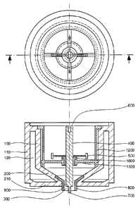
FIG. I shows a reaction chamber according to the invention in a view from the
top and in cross
section
FIG. 2 shows a multiplicity of reaction chambers according to the invention
stacked one above the
other in cross section
FIG. 3 shows a chemical reactor according to the invention
FIG. 1 shows a reaction chamber according to the invention in a combined view
having a plan view
(upper part of the figure) and a side cross sectional view (lower part of the
figure). The reaction
chamber has a casing 100, a floor 200 inclined in this case at 330, and also
an opening 300 in the floor
200. The casing 100 and the floor 200 are constructed jointly as heating and
cooling casing. For this
purpose, a double-shell construction having a second casing 110 and a second
floor 210 is used, which
contains a cavity 120. Through this cavity 120, a heating or cooling medium
for heat exchange can be
conducted by means of inlets and outlets that are not shown here. The chamber
floor is also heated or
cooled thereby and not only the casing as in many conventional structures of
kettle reactors.
The reaction chamber in addition has an agitator shaft 400 for driving
agitator elements 500. The
beginning 600 of the agitator shaft 400 is shown at the top in FIG. 1, and the
end 700 at the bottom.
Beginning 600 and end 700 of the agitator shaft 400 are designed as male and
female, respectively,
connectors or plug-in connections, in such a manner that when a plurality of
reaction chambers are
stacked one above the other the agitator shafts of two successive reaction
chambers engage in one
another in a form-fitting manner in the direction of rotation. Then they form
a combined agitator shaft
with which the agitator elements of the individual chambers can be driven.
CA 2952110 2018-05-24
81801651
- 9 -
Within the reaction chamber, the agitator shaft 400 is received by a bearing
1000, which itself is
supported via corresponding supports 1100 in the reaction chamber. In
addition, within the reaction
chamber, baffles 1200 are present which, in interaction with agitator elements
500, ensure a relatively
high mixing of the reactor contents.
In the opening 300 of the floor 200 of the reaction chamber, in addition there
is a removable sleeve
800 which (as shown at the bottom here) projects out of the reaction chamber.
The sleeve 800 is
arranged in alignment with the axis of rotation of the agitator shaft 400. In
FIG. 1, sleeve and axis of
rotation are centered in the reaction chamber.
The internal diameter of the sleeve 800 is greater than the diameter of the
agitator shaft 400 at the
height of the sleeve 800. In addition, the agitator shaft 400 projects through
the sleeve 800 out of the
reaction chamber. As a result, a gap 900 is formed between agitator shaft 400
and sleeve 800, through
which gap, in the case of a plurality of reaction chambers stacked one above
the other, a mass transfer
can take place between one chamber and the adjacent chamber.
To increase the versatility and modularity of the use of the reaction chambers
according to the
invention, not only is the sleeve 800 detachable, but also the agitator shaft
400, the bearing 1000, the
support 1100 and the baffle 1200, and therefore are usable for other
structures adapted to a specific
application case.
FIG. 2 shows a cross-sectional view of three reaction chambers according to
the invention stacked one
above the other, as can occur in a chemical reactor according to the
invention. The individual
chambers are as shown and explained in FIG. I. As may be seen, the reaction
chambers are designed in
such a manner that the bottom seal of one chamber forms the upper seal of the
chamber lying
therebeneath. As a result, a chemical reactor may be made up in a modular
mariner. Obviously, a
sealing composition can also further be provided between the individual
reaction chambers.
The agitator shafts 400 engaging in one another in a form-fitting manner in
the direction of rotation
form, as related to transmission of a torque, a combined agitator shaft. In
this case, it can be noted that
shear forces also occur in the gap 900, which is formed between agitator shaft
400 and sleeve 800 and
through which a mass transfer can take place between adjacent reaction
chambers. Therefore, there is
no "dead zone" in which the contents of the reaction chamber are not
thoroughly agitated.
The width of the gap 900 and therefore the mass transfer between the
individual reaction chambers
may be established by means of the diameter of the agitator shaft and/or the
internal diameter of the
CA 2952110 2018-05-24
BTS133054-Foreign Countries
CA 02952110 2016-12-13
- 10 -
sleeves 800. For practical reasons, it is preferred only to exchange the
sleeves 800 if another gap width
between the chambers is desired. Owing to the fact that the sleeves 800 are
removable, this is effected
in a simple manner.
FIG. 3 shows schematically a chemical reactor according to the invention with
a total of seven reaction
chambers according to the invention. The reaction chambers are stacked one
above the other in a
similar manner to the arrangement shown in FIG. 2 and are sealed at top and
bottom with a cover plate
2000 and base plate 2010. The arrangement is mechanically stabilized by means
of tie rods 2100 and
nuts 2110.
A torque for driving the agitator shafts is transmitted by means of coupling
2200 to the agitator shafts
in the interior of the chemical reactor. In the cover plate 2000, in addition
accesses 2300 and 2310 are
arranged, through which substances or measuring sensors can be introduced into
the topmost reaction
chamber. Such an access 2320 is also located at the outlet 2400 which is
integrated into the base plate
2010.
Via the feed lines 2500 and the outlets 2510, the heating/cooling casings of
the individual reaction
chambers can be provided with a heating or cooling medium. An individual
heating or cooling is
possible.
The individual reaction chambers are accessible via accesses 2600 and 2610 for
material introduction,
material discharge and measuring sensors. Via a suitably chosen piping
installation, in addition, a
bridging of a reaction chamber can be achieved, if a fault occurs during
running operation.