Note: Descriptions are shown in the official language in which they were submitted.
CA 02952211 2016-12-13
TITLE
DISPERSING AND FLATTENING APPARATUS FOR UNIFORM DRYING OF
TRANSPORTATION COALS IN COAL DRYER USING REHEAT STEAM
TECHNICAL FIELD
The present invention relates to an apparatus for
dispersing and flattening transportation coals in a coal
dryer using reheat steam and, more particularly, to an
apparatus that reduces loads of piles of coals that are
input from a fixed quantity coal supplier via a pulverizer
to a multi-stage dryer and are transferred, and uniformly
disperses and flattens the piles of the coals, thereby
improving drying efficiency, in the multi-stage dryer that
dries coals using reheat steam.
BACKGROUND ART
In general, in a thermal power plant that generates
power by using coal as fuel, coals of approximately 180
ton/hr per 500MW are combusted, and each pulverizer supplies
coals of approximately 37 ton to a boiler. In a thermal
power plant of 500MW which uses coal, approximately six coal
storage silos each having a capacity of approximately 500
ton are installed. Five of them are for normally supplying
coals and the other one is operated as a coal storage silo
that preliminarily stores coal that may be used for a
1
CA 02952211 2016-12-13
predetermined period of time.
In addition, in the thermal power plant that generates
power by using coal as fuel, the standard thermal power
design criterion for coal is designed to use a low moisture
bituminous coal of 6,080 Kcal/Kg and 10% or less. In some
thermal power plants, imported coals are used. Among the
imported coal, some sub-bituminous coals has an average
moisture water content of 17% or more, so that combustion
efficiency of the boiler is reduced. When the standard
thermal power combustion limit is 5,400 Kcal/Kg and a
caloric value of the coals is low, a reduction in a power
generation amount and an increase in a fuel consumption
amount are predicted due to a reduction in the combustion
efficiency. In addition, when sub-bituminous coals which are
high-moisture low caloric coals are used, a moisture content
thereof is higher than a design reference, so that a
transfer system that carries the coals may not be smoothly
operated, efficiency when the coals are pulverized by the
pulverizer may be reduced, combustion efficiency may be
reduced due to partial incomplete combustion, and windage of
distribution of heat generated in the boiler an abnormal
operation may occur. However, in the thermal power plant, to
reduce fuel costs, a usage ratio of sub-bituminous coals has
been gradually increased to approximately 41-60%.
2
CA 02952211 2016-12-13
Further, because the global economic recovery is
expected and safety issues of a nuclear power plant are
faced due to destruction of a nuclear power plant resulting
from a Japanese huge earthquake, preference of the thermal
power plant becomes high, and thus, it is predicted that
demands and prices of the coals are consistently increased.
An environment of the world coal market is changed from a
customer-centered environment to a supplier-centered
environment, and thus, stable supply and demand of coals is
different. Further, it is predicted that a production volume
of high caloric coals is maintained at a current level, and
thus, unbalance of the supply and demand of the coals is
predicted.
Although a ratio of low caloric coals among the total
deposits of the world's coals is approximately 47%, the low
caloric coals have low caloric values and high moisture
contents, and thus, the high-moisture low caloric coals have
difficulty in complete combustion, for example, a combustion
failure during combustion. Accordingly, the low caloric
coals are ignored in the market. Globally, until recent
years, tpere has been a high tendency of relying on stable
petroleum prices and low production unit prices of the
nuclear power plant. However, in recent years, a lot of
constructions of the thermal power plants that use coals are
3
CA 02952211 2016-12-13
planed due to a sharp rise in petroleum prices and a sense
of insecurity to the nuclear power generation.
As the conventional technology of drying coals (thermal
drying), a rotary drying scheme of drying internal coal
particles using high temperature gas while a cylindrical
shell into which coals are input is rotated, a flash
pneumatic drying scheme of drying coals by raising high-
temperature drying gas from below to top while coals are
supplied from top to below, and a fluid-bed drying scheme of
drying coals by upward raising high-temperature drying gas
with fine particles are mainly used.
Moisture of the coals is classified into surface
moisture that is attached to pores between coal particles
and bound moisture that is coupled to pores inside the coals.
Most of the surface moisture is moisture that is sprayed
during a washing process in a producing area, transportation
and storing, and an amount of the surface moisture is
determined based on a surface area and absorptivity. Further,
as particles becomes smaller, the surface area becomes
larger and capillary tubes between the particles are formed,
so that moisture is contained in the coals, and thus, a
moisture content is increased. The bound moisture is formed
at a creation time of the coals, and bound moistures of
brown coal, soft coal (bituminous coal and sub-bituminous
coal) and anthracite coal are smaller in the sequence of the
4
CA 02952211 2016-12-13
brown coal, the soft coal (bituminous coal and sub-
bituminous coal) and the anthracite coal. When a large
amount of moisture is included in coals, caloric values are
reduced and transportation costs are increased, so that it
is required to control moisture during processes of mixing,
pulverizing and separating coals.
In addition, a problem occurs in that moisture included
in coals cannot be effectively dried even by spraying reheat
steam in a state in which input coals are not uniformly
dispersed, in an apparatus for drying coals by spraying
high-temperature reheat steam below a dryer while the
pulverized coals are transferred through a multi-stage dryer,
that is, a conveyor having a plurality of through-holes
formed therein through which reheat steam passes or a
plurality of transfer plates that are coupled to each other.
Accordingly, problems occur in that stages or lengths of the
dryer for drying coals should be enlarged, a supply amount
of the reheat steam for drying should be increased, and thus,
costs and times according to drying of coals are increased.
Korean Patent No. 10-0960793 as the prior art related
to the present invention discloses that a low grade coal
stabilizer includes a wave-type vibration flow plate for
uniform mixing with heavy oil ash powders that are input
into primarily dried low grade coal to improve drying
efficiency. The vibration flow'plate, which uniformly mixes
CA 02952211 2016-12-13
the low grade coal and the heavy oil ash powders with each
other, has an inherent problem in that because drying steam
for drying coals is not uniformly sprayed onto surfaces of
the coals, drying efficiency may be reduced.
DISCLOSURE
TECHNICAL PROBLEM
The present invention is conceived to solve the above-
described problems, and an aspect of the present invention
is to effectively dry coals by reheat steam that is sprayed
to the coals, by reducing loads and, at the same time,
uniformly dispersing and flatly transferring the coals while
piles of the coals input into a dryer pass through a multi-
stage pulverizer, in an apparatus that dries coals by using
reheat steam while the coal used as fuel of the thermal
power plant is transferred to a dryer.
Further, another aspect of the present invention is to
reduce a use amount of fuel by improving combustion
efficiency of a boiler of a thermal power plant by
increasing a caloric value of coals by maintaining a proper
water content due to effective drying of the coals.
Further, yet another aspect of the present invention is
to provide a drying technology that may prevent an
environment problem resulting from incomplete combustion of
6
CA 02952211 2016-12-13
coals by adjusting moisture contained in the coals and a
technology that may be applied to a thermal power plant.
TECHNICAL SOLUTION
To achieve the above objects, the present invention
provides a dispersing and flattening apparatus for uniform
drying of a transportation coals in a coal dryer using
reheat steam, the coal dryer including: = a first coal dryer
that includes a pair of first driving sprockets and a pair
of first driven sprockets that are fastened to each other by
first chains to be spaced apart from each other by a
specific, distance, a plurality of first transfer plates that
are hinge-coupled to between the first chains, a pair of
first guide rails that are installed below a first upper
chain connected between the first driving sprockets and the
first driven sprockets to horizontally support first upper
transfer plates, a pair of second guide rails that are
installed below a first lower chain connected between the
first driving sprockets and the first driven sprockets to
horizontally support first lower transfer plates, a first
steam chamber that is installed below the first upper chain
to spray reheat steam supplied by a reheater, a second steam
chamber that is installed below the first lower chain to
spray the reheat steam supplied by the reheater, a first
flue gas chamber that is installed above the first upper
7
CA 02952211 2016-12-13
chain to collect flue gas, and a second flue gas chamber
that is installed above the first lower chain to collect
flue gas; and a second coal dryer that includes a pair of
second driving sprockets and a pair of second driven
sprockets that are fastened to each other by second chains
to be spaced apart from each other by a specific distance, a
plurality of second transfer plates that are hinge-coupled
to between the second chains, a pair of third guide rails
that are installed below a second upper chain connected
between the second driving sprockets and the second driven
sprockets to horizontally support second upper transfer
plates, a pair of fourth guide rails that are installed
below a second lower chain connected between the second
driving sprockets and the second driven sprockets to
horizontally support second upper transfer plates, a third
steam chamber that is installed below the second upper chain
to spray the reheat steam supplied by the reheater, a fourth
steam chamber that is installed below the second lower chain
to spray the reheat steam supplied by the reheater, a third
flue gas chamber that is installed above the second upper
chain to collect flue gas, and a fourth flue gas chamber
that is installed above the lower chain to collect flue gas,
wherein coals that are primarily dried by the first coal
dryer are input into the second coal dryer to be secondarily
dried, and the dispersing and flattening apparatus
including: a column-shaped body that is installed on
8
CA 02952211 2016-12-13
surfaces of the plurality of first transfer plates and
second transfer plates, which faces an upper side, at a
specific interval; a division boss that protrudes from a
central portion of a front surface of the body to divide and
disperse a central portion of piles of coals input from a
fixed quantity coal supplier onto the surfaces of the first
transfer plates and the second transfer plates, which face
an upper side, into left and right parts; and a pair of
fixing members that are fixed at upper ends of the first
guide rails and the second guide rails that horizontally
support the first transfer plates and at upper ends of the
third guide rails and the fourth guide rails that
horizontally support the second transfer plates to fixedly
support opposite ends of the body, wherein the piles of the
coals that are transferred on the surfaces of the first
transfer plates and the second transfer plates, which face
an upper side, are flattened at a specific height so that
reheat steam sprayed while passing through the first
transfer, plates and the second transfer plates uniformly
comes into contact with surfaces of coal particles.
Further, the present invention provides a dispersing
and flattening apparatus for uniform drying of a
transportation coals in a coal dryer using reheat steam, the
coal dryer including: a first coal dryer that includes a
pair of first driving sprockets and a pair of first driven
9
CA 02952211 2016-12-13
sprockets that are fastened to each other by first chains to
be spaced apart from each other by a specific distance, a
plurality of first transfer plates that are hinge-coupled to
between the first chains, a pair of first guide rails that
are installed below a first upper chain connected between
the first driving sprockets and the first driven sprockets
to horizontally support first upper transfer plates, a pair
of second guide rails that are installed below a first lower
chain connected between the first driving sprockets and the
first driven sprockets to horizontally support first lower
transfer plates, a first steam chamber that is installed
below the first upper chain to spray reheat steam supplied
by a reheater, a second steam chamber that is installed
below the first lower chain to spray the reheat steam
supplied by the reheater, a first flue gas chamber that is
installed above the first upper chain to collect flue gas,
and a second flue gas chamber that is installed above the
first lower chain to collect flue gas; and a second coal
dryer that includes a pair of second driving sprockets and a
pair of second driven sprockets that are fastened to each
other by second chains to be spaced apart from each other by
a specific distance, a plurality of second transfer plates
that are hinge-coupled to between the second chains, a pair
of third guide rails that are installed below a second upper
chain connected between the second driving sprockets and the
second driven sprockets to horizontally support second upper
CA 02952211 2016-12-13
transfer plates, a pair of fourth guide rails that are
installed below a second lower chain connected between the
second driving sprockets and the second driven sprockets to
horizontally support second upper transfer plates, a third
steam chamber that is installed below the second upper chain
to spray the reheat steam supplied by the reheater, a fourth
steam chamber that is installed below the second lower chain
to spray the reheat steam supplied by the reheater, a third
flue gas chamber that is installed above the second upper
chain to collect flue gas, and a fourth flue gas chamber
that is installed above the lower chain to collect flue gas,
wherein first transfer rollers are hinge-coupled to between
centers of opposite sides of each first transfer plate and
the first chains, respectively, first auxiliary rollers are
hinge-coupled to side surfaces of the first transfer plate
on left and right sides of the first transfer rollers,
respectively, second transfer rollers are hinge-coupled to
between centers of opposite sides of each second transfer
plate and the second chains, respectively, second auxiliary
rollers 'are hinge-coupled to side surfaces of the second
transfer plate on left and right sides of the second
transfer rollers, respectively, first guide bars that
unidirectionally rotate and upwardly support first lower
transfer plates separated from the second guide rails are
installed from an upper side via a lateral side to a lower
side of the first driving sprockets, second guide bars that
11
CA 02952211 2016-12-13
unidirectionally rotate and downwardly support first upper
transfer, plates separated from the first guide rails are
installed from a lower side via a lateral side to an upper
side of the first driven sprockets, third guide bars that
unidirectionally rotate and upwardly support second lower
transfer plates separated from the fourth guide rails are
installed from an upper side via a lateral side to a lower
side of the second driving sprockets, fourth guide bars that
unidirectionally rotate and downwardly support second upper
transfer plates separated from the third guide rails are
installed from a lower side via a lateral side to an upper
side of the second driven sprockets, a fixed quantity coal
supplier that supplies coals to surfaces of the first
transfer plates, which face an upper side, at a fixed
quantity is included, and coals that are primarily dried by
the first coal dryer are input into the second coal dryer to
be secondarily dried, and the dispersing and flattening
apparatus including: a column-shaped body that is installed
on surfaces of the plurality of first transfer plates and
second transfer plates, which faces an upper side, at a
specific interval; a division boss that protrudes from a
central portion of a front surface of the body to divide and
disperse 'a central portion of piles of coals input from the
fixed quantity coal supplier to the surfaces of the first
transfer plates and the second transfer plates, which face
an upper side, into left and right parts; and a pair of
12
CA 02952211 2016-12-13
fixing members that are fixed at upper ends of the first
guide rails and the second guide rails that horizontally
support the first transfer plates and at upper ends of the
third guide rails and the fourth guide rails that
horizontally support the second transfer plates to fixedly
support opposite ends of the body, wherein the piles of the
coals that are transferred on the surfaces of the first
transfer plates and the second transfer plates, which face
an upper side, are flattened at a specific height so that
reheat steam sprayed while passing through the first
transfer plates and the second transfer plates uniformly
comes into contact with surfaces of coal particles.
Further, in the present invention, bodies having
division bosses formed therein may be fixedly installed at
front ends of the first flue gas chamber, the second flue
gas chamber, the third flue gas chamber and the fourth flue
gas chamber, respectively.
Further, in the present invention, a bottom surface of
the body may have a shape of which a thickness becomes
thicker as it goes from an end of a blade of the division
boss to a rear surface of the body and which is inclined at
a specific slope.
Further, in the present invention, a plurality of
wedges may be spaced apart from each other at a specific
interval,to protrude from the bottom surface of the body.
13
CA 02952211 2016-12-13
Further, in the present invention, the bottom surface
of the body may have a shape of which a thickness becomes
thicker as it goes from the end of the blade of the division
boss to the rear surface of the body and which has inclined
surfaces inclined at a specific slope and the plurality of
wedges may be spaced apart from each other at a specific
interval to protrude from the bottom surface of the body.
Further, the present invention provides a dispersing
and flattening apparatus for uniform drying of a
transportation coals in a coal dryer using reheat steam, the
coal dryer including: a first coal dryer that includes a
pair of first driving sprockets and a pair of first driven
sprockets that are fastened to each other by first chains to
be spaced apart from each other by a specific distance, a
plurality of first transfer plates that are hinge-coupled to
between the first chains, a pair of first guide rails that
are installed below a first upper chain connected between
the first driving sprockets and the first driven sprockets
to horizontally support first upper transfer plates, a pair
of second guide rails that are installed below a first lower
chain connected between the first driving sprockets and the
first driven sprockets to horizontally support first lower
transfer plates, a first steam chamber that is installed
below the first upper chain to spray reheat steam supplied
by a reheater, a second steam chamber that is installed
14
CA 02952211 2016-12-13
below the first lower chain to spray the reheat steam
supplied by the reheater, a first flue gas chamber that is
installed above the first upper chain to collect flue gas,
and a second flue gas chamber that is installed above the
first lower chain to collect flue gas; and a second coal
dryer that includes a pair of second driving sprockets and a
pair of second driven sprockets that are fastened to each
other by second chains to be spaced apart from each other by
a specific distance, a plurality of second transfer plates
that are hinge-coupled to between the second chains, a pair
of third, guide rails that are installed below a second upper
chain connected between the second driving sprockets and the
second driven sprockets to horizontally support second upper
transfer plates, a pair of fourth guide rails that are
installed below a second lower chain connected between the
second driving sprockets and the second driven sprockets to
horizontally support second upper transfer plates, a third
steam chamber that is installed below the second upper chain
to spray the reheat steam supplied by the reheater, a fourth
steam chamber that is installed below the second lower chain
to spray the reheat steam supplied by the reheater, a third
flue gas chamber that is installed above the second upper
chain to collect flue gas, and a fourth flue gas chamber
that is installed above the lower chain to collect flue gas,
wherein coals that are primarily dried by the first coal
dryer are input into the second coal dryer to be secondarily
CA 02952211 2016-12-13
dried, and the dispersing and flattening apparatus
including: a column-shaped body that is installed on
surfaces of the plurality of first transfer plates and
second transfer plates, which face an upper side, at a
specific interval; a division boss that protrudes from a
central portion of a front surface of the body to divide and
disperse a central portion of piles of coals input from a
fixed quantity coal supplier to the surfaces of the first
transfer, plates and the second transfer plates, which face
an upper side, into left and right parts; a dispersion boss
that has an edge that protrudes from a front side of a lower
edge of the division boss and a blade that protrudes to
opposite surfaces of the lower edge of the division boss and
has inclined surfaces having a specific slope, which are
formed from the edge to the blade and become wider as they
go from above to below; and a pair of fixing members that
are fixed at upper ends of the first guide rails and the
second guide rails that horizontally support the first
transfer plates and at upper ends of the third guide rails
and the fourth guide rails that horizontally support the
second transfer plates to fixedly support opposite ends of
the body, wherein piles of coals that are transferred on the
surfaces of the first transfer plates and the second
transfer plates, which face an upper side, are flattened at
a specific height so that reheat steam sprayed while passing
through the first transfer plates and the second transfer
16
CA 02952211 2016-12-13
plates uniformly comes into contact with surfaces of coal
particles.
Further, in the present invention, the dispersion boss
may have a second intersection line in which the opposite
inclined surfaces of the dispersion boss meet each other, a
third intersection line in which a side surface of the
division boss and the inclined surfaces of the dispersion
boss meet each other, a fourth intersection line
corresponding to the blade, in which a bottom surface and
the edge of the dispersion boss meet each other, a first
intersection point in which the second intersection line and
the third intersection line meet each other, a second
intersection point in which the second intersection line and
the fourth intersection line meet each other, and a third
intersection point in which the third intersection line and
the fourth intersection line meet each other.
Further, in the present invention, the dispersion boss
may have a second intersection line in which the opposite
inclined surfaces of the dispersion boss meet each other, a
third intersection line in which a side surface of the
division boss and the inclined surfaces of the dispersion
boss meet each other, a fourth intersection line
corresponding to the blade, in which a bottom surface and
the edge of the dispersion boss meet each other, a fifth
intersection line in which side surfaces and the body of the
17
,
CA 02952211 2016-12-13
dispersion boss meet each other, a first intersection point
in which the second intersection line and the third
intersection line meet each other, a second intersection
point in which the second intersection line and the fourth
intersection line meet each other, a third. intersection line
in which the fourth intersection line and the fifth
intersection line meet each other, and a fourth intersection
point in which the third intersection line and the fifth
intersection line meet each other, wherein the third
intersection line and the fourth intersection line may be
parallel to each other side by side.
Further, in the present invention, a plurality of
dispersion bosses may be vertically formed on side surfaces
of the division boss.
Further, in the present invention, bodies to which
division bosses having dispersion bosses formed therein are
integrally coupled may be fixedly installed at front ends of
the first flue gas chamber, the second flue gas chamber, the
third flue gas chamber and the fourth flue gas chamber,
respectiVely.
Further, in the present invention, a bottom surface of
the body may have a shape of which a thickness becomes
thicker as it goes from the second intersection point of the
division boss to a rear surface of the body and which is
inclined'at a specific slope.
18
CA 02952211 2016-12-13
Further, the present invention provides a dispersing
and flattening apparatus for uniform drying of a
transportation coals in a coal dryer using reheat steam, the
coal dryer including: a first coal dryer that includes a
pair of first driving sprockets and a pair of first driven
sprockets that are fastened to each other by first chains to
be spaced apart from each other by a specific distance, a
pluralitY of first transfer plates that are hinge-coupled to
between the first chains, a pair of first guide rails that
are installed below a first upper chain connected between
the first driving sprockets and the first driven sprockets
to horizontally support first upper transfer plates, a pair
of second guide rails that are installed below a first lower
chain connected between the first driving sprockets and the
first driven sprockets to horizontally support first lower
transfer plates, a first steam chamber that is installed
below the first upper chain to spray reheat steam supplied
by a re4eater, a second steam chamber that is installed
below the first lower chain to spray the reheat steam
supplied by the reheater, a first flue gas chamber that is
installed above the first upper chain to collect flue gas,
and a second flue gas chamber that is installed above the
first lower chain to collect flue gas; and a second coal
dryer that includes a pair of second driving sprockets and a
pair of second driven sprockets that are fastened to each
other by second chains to be spaced apart from each other by
19
CA 02952211 2016-12-13
a specific distance, a plurality of second transfer plates
that are hinge-coupled to between the second chains, a pair
of third guide rails that are installed below a second upper
chain connected between the second driving sprockets and the
second driven sprockets to horizontally support second upper
transfer plates, a pair of fourth guide rails that are
installed below a second lower chain connected between the
second driving sprockets and the second driven sprockets to
horizontally support second upper transfer plates, a third
steam chamber that is installed below the second upper chain
to spray the reheat steam supplied by the reheater, a fourth
steam chamber that is installed below the second lower chain
to spray the reheat steam supplied by the reheater, a third
flue gas chamber that is installed above the second upper
chain to collect flue gas, and a fourth flue gas chamber
that is installed above the lower chain to collect flue gas,
wherein coals that are primarily dried by the first coal
dryer are input into the second coal dryer to be secondarily
dried, and the dispersing and flattening apparatus including
a plurality of flatteners, each of which includes a column-
shaped body, a division boss that protrudes from a central
portion of a front surface of the body to divide and
disperse a central portion of piles of input coals into left
and right parts, and a pair of fixing members that fixedly
support opposite ends of the body, wherein the plurality of
flatteners are installed at a specific interval such that a
CA 02952211 2016-12-13
preceding flattener is installed to have a predetermined-
height step from the surfaces of the first transfer plates
to be spaced apart from a following flattener such that they
become lower as they go from front to rear, and the
plurality of flatteners reduce loads of piles of transferred
coals by flattening the piles of the coals transferred on
the surfaces of the first transfer plates, which face an
upper side, such that the piles of the coals become
gradually lower at a specific height interval, and allow
reheat steam sprayed while passing through the first
transfer plates to uniformly come into contact with surfaces
of coal particles.
Further, the present invention provides a dispersing
and flattening apparatus for uniform drying of a
transportation coals in a coal dryer using reheat steam, the
coal dryer including: a first coal dryer that includes a
pair of first driving sprockets and a pair of first driven
sprockets that are fastened to each other by first chains to
be spaced apart from each other by a specific distance, a
plurality of first transfer plates that are hinge-coupled to
between the first chains, a pair of first guide rails that
are installed below a first upper chain connected between
the first driving sprockets and the first driven sprockets
to horizontally support first upper transfer plates, a pair
of second guide rails that are installed below a first lower
21
CA 02952211 2016-12-13
chain connected between the first driving sprockets and the
first driven sprockets to horizontally support first lower
transfer plates, a first steam chamber that is installed
below the first upper chain to spray reheat steam supplied
by a reheater, a second steam chamber that is installed
below the first lower chain to spray the reheat steam
supplied by the reheater, a first flue gas chamber that is
installed above the first upper chain to collect flue gas,
and a second flue gas chamber that is installed above the
first lower chain to collect flue gas; and a second coal
dryer that includes a pair of second driving sprockets and a
pair of second driven sprockets that are fastened to each
other by second chains to be spaced apart from each other by
a specific distance, a plurality of second transfer plates
that are hinge-coupled to between the second chains, a pair
of third guide rails that are installed below a second upper
chain connected between the second driving sprockets and the
second driven sprockets to horizontally support second upper
transfer plates, a pair of fourth guide rails that are
installed below a second lower chain connected between the
second driving sprockets and the second driven sprockets to
horizontally support second upper transfer plates, a third
steam chamber that is installed below the second upper chain
to spray the reheat steam supplied by the reheater, a fourth
steam chamber that is installed below the second lower chain
to spray the reheat steam supplied by the reheater, a third
22
CA 02952211 2016-12-13
flue gas chamber that is installed above the second upper
chain to collect flue gas, and a fourth flue gas chamber
that is installed above the lower chain to collect flue gas,
wherein first transfer rollers are hinge-coupled to between
centers of opposite sides of each first transfer plate and
the first chains, respectively, first auxiliary rollers are
hinge-coupled to side surfaces of the first transfer plate
on left and right sides of the first transfer rollers,
respectively, second transfer rollers are hinge-coupled to
between centers of opposite sides of each second transfer
plate and the second chains, respectively, second auxiliary
rollers are hinge-coupled to side surfaces of the second
transfer plate on left and right sides of the second
transfer rollers, respectively, first guide bars that
unidiredLionally rotate and upwardly support first lower
transfer plates separated from the second guide rails are
installed from an upper side via a lateral side to a lower
side of the first driving sprockets, second guide bars that
unidirectionally rotate and downwardly support first upper
transfer- plates separated from the first guide rails are
installed from a lower side via a lateral side to an upper
side of the first driven sprockets, third guide bars that
unidirectionally rotate and upwardly support second lower
transfer plates separated from the fourth guide rails are
installed from an upper side via a lateral side to a lower
side of the second driving sprockets, fourth guide bars that
23
,
CA 02952211 2016-12-13
unidirectionally rotate and downwardly support second upper
transfer, plates separated from the third guide rails are
installed from a lower side via a lateral side to an upper
side of the second driven sprockets, a fixed quantity coal
supplier that supplies coals to surfaces of the first
transfer plates, which face an upper side, at a fixed
quantity is included, and coals that are primarily dried by
the first coal dryer are input into the second coal dryer to
be secondarily dried, and the dispersing and flattening
apparatus including a plurality of flatteners, each of which
includes a column-shaped body, a division boss that
protrudes from a central portion of a front surface of the
body to divide and disperse a central portion of piles of
input coals into left and right parts, and a pair of fixing
members that fixedly support opposite ends of the body,
wherein the plurality of flatteners are installed at a
specific interval such that a preceding flattener is
installed to have a predetermined-height step from the
surfaces of the first transfer plates to be spaced apart
from a following flattener such that they become lower as
they go from front to rear, and the plurality of flatteners
reduce loads of piles of transferred coals by flattening the
piles of, the coals transferred on the surfaces of the first
transfer plates, which face an upper side, such that the
piles of the coals become gradually lower at a specific
height interval, and allow reheat steam sprayed while
24
CA 02952211 2016-12-13
passing through the first transfer plates to uniformly come
into contact with surfaces of coal particles.
Further, in the present invention, the flatteners may
include a first flattener to a fourth flattener.
Further, in the present invention, through-holes may be
formed at left and right sides of the bodies of the second
flattener to the fourth flattener, respectively.
Further, in the present invention, the plurality of
flatteners may be installed at front ends of or inside the
first flue gas chamber, the second flue gas chamber, the
third flue gas chamber and the fourth flue gas chamber,
respectively.
Further, in the present invention, each flattener may
further include a dispersion boss that has an edge that
protrude's from a front side of a lower edge of the division
boss and a blade that protrudes to opposite surfaces of the
lower edge of the division boss and has inclined surfaces
having a specific slope, which are formed from the edge to
the blade and become wider as they go from above to below.
Further, the present invention provides a dispersing
and flattening apparatus for uniform drying of a
transportation coals in a coal dryer using reheat steam, the
coal dryer including: a first coal dryer that includes a
pair of first driving sprockets and a pair of first driven
sprocket8 that are fastened to each other by first chains to
CA 02952211 2016-12-13
be spaced apart from each other by a specific distance, a
plurality of first transfer plates that are hinge-coupled to
between the first chains, a pair of first guide rails that
are installed below a first upper chain connected between
the first driving sprockets and the first driven sprockets
to horizontally support first upper transfer plates, a pair
of second guide rails that are installed below a first lower
chain connected between the first driving sprockets and the
first driven sprockets to horizontally support first lower
transfer plates, a first steam chamber that is installed
below the first upper chain to spray reheat steam supplied
by a reheater, a second steam chamber that is installed
below the first lower chain to spray the reheat steam
supplied by the reheater, a first flue gas chamber that is
installed above the first upper chain to collect flue gas,
and a second flue gas chamber that is installed above the
first lower chain to collect flue gas; and a second coal
dryer that includes a pair of second driving sprockets and a
pair of second driven sprockets that are fastened to each
other by second chains to be spaced apart from each other by
a specific distance, a plurality of second transfer plates
that are hinge-coupled to between the second chains, a pair
of third guide rails that are installed below a second upper
chain cohnected between the second driving sprockets and the
second driven sprockets to horizontally support second upper
transfer plates, a pair of fourth guide rails that are
26
CA 02952211 2016-12-13
installed below a second lower chain connected between the
second driving sprockets and the second driven sprockets to
horizontally support second upper transfer plates, a third
steam chamber that is installed below the second upper chain
to spray the reheat steam supplied by the reheater, a fourth
steam chamber that is installed below the second lower chain
to spray the reheat steam supplied by the reheater, a third
flue gas chamber that is installed above the second upper
chain to collect flue gas, and a fourth flue gas chamber
that is installed above the lower chain to collect flue gas,
wherein ,coals that are primarily dried by the first coal
dryer are input into the second coal dryer to be secondarily
dried, and the dispersing and flattening apparatus
including: first and second dispersion flatteners, each of
which includes a column-shaped body, a division boss that
protrudes from a central portion of a front surface of the
body, a fixing shaft that is fixed to an upper central
portion of a flat surface of the body, a restoration member
that is coupled between the fixing shaft and the body to
horizontally and elastically support the body with respect
to the fixing shaft, and a fixing member that fixedly
supports an upper end of the fixing shaft; a flattener that
includes a column-shaped body, a division boss that
protrudes from a central portion of a front surface of the
body, and a pair of fixing members that fixedly support
opposite ends of the body; and a pair of transportation coal
27
CA 02952211 2016-12-13
guide plates that are installed between the first dispersion
flattener and the second dispersion flattener and between
the second dispersion flattener and the flattener toward
insides of the first transfer plates at a specific angle and
are located on surfaces of the first transfer plates, and
upper ends of which are fixedly supported by support
members, wherein the first dispersion flattener, the second
dispersion flattener and the flattener are installed at a
specific, interval to have a predetermined-height step from
the surfaces of the first transfer plates as they go from
front to rear, and the first dispersion flattener and the
second dispersion flattener disperse piles of coals
transferred on the surfaces of the first transfer plates,
which face an upper side, such that the piles of the coals
are not biased to any one side, and the piles of the
transferred coals are flattened to become lower by a
predetermined-height difference while passing through the
first dispersion flattener, the second dispersion flattener
and the flattener so that loads of the piles of the
transferred coals are flattened and the reheat steam sprayed
while passing through the first transfer plates uniformly
comes into contact with surfaces of coal particles.
Further, in the present invention, a pair of
transportation coal guide plates may be installed in front
of the first dispersion flattener.
28
CA 029211 2016--13
Further, in the present invention, the first dispersion
flattener, the second dispersion flattener, the flattener
and the transportation coal guide plates between the first
dispersion flattener and the second dispersion flattener and
between the second dispersion flattener and the flattener
may be installed at front ends of or inside the first flue
gas chamber, the second flue gas chamber, the third flue gas
chamber and the fourth flue gas chamber, respectively.
Further, in the present invention, each of the first
dispersion flattener, the second dispersion flattener and
the flattener may further include a dispersion boss that has
an edge that protrudes from a front side of a lower edge of
the division boss and a blade that protrudes to opposite
surfaces of the lower edge of the division boss and has
inclined surfaces having a specific slope, which are formed
from the edge to the blade and become wider as they go from
above to,below.
Further, the present invention provides a dispersing
and flattening apparatus for uniform drying of a
transportation coals in a coal dryer using reheat steam, the
coal dryer including: a first coal dryer that includes a
pair of ,first driving sprockets and a pair of first driven
sprockets that are fastened to each other by first chains to
be spaced apart from each other by a specific distance, a
plurality of first transfer plates that are hinge-coupled to
29
CA 02952211 2016-12-13
between the first chains, a pair of first guide rails that
are installed below a first upper chain connected between
the first driving sprockets and the first driven sprockets
to horizontally support first upper transfer plates, a pair
of second guide rails that are installed below a first lower
chain connected between the first driving sprockets and the
first driven sprockets to horizontally support first lower
transfer plates, a first steam chamber that is installed
below the first upper chain to spray reheat steam supplied
by a re,heater, a second steam chamber that is installed
below the first lower chain to spray the reheat steam
supplied by the reheater, a first flue gas chamber that is
installed above the first upper chain to collect flue gas,
and a second flue gas chamber that is installed above the
first lower chain to collect flue gas; and a second coal
dryer that includes a pair of second driving sprockets and a
pair of second driven sprockets that are fastened to each
other by second chains to be spaced apart from each other by
a specific distance, a plurality of second transfer plates
that are hinge-coupled to between the second chains, a pair
of third guide rails that are installed below a second upper
chain connected between the second driving sprockets and the
second driven sprockets to horizontally support second upper
transfer plates, a pair of fourth guide rails that are
installed below a second lower chain connected between the
second driving sprockets and the second driven sprockets to
CA 02952211 2016-12-13
horizontally support second upper transfer plates, a third
steam chamber that is installed below the second upper chain
to spray the reheat steam supplied by the reheater, a fourth
steam chamber that is installed below the second lower chain
to spray the reheat steam supplied by the reheater, a third
flue gas chamber that is installed above the second upper
chain to collect flue gas, and a fourth flue gas chamber
that is installed above the lower chain to collect flue gas,
wherein coals that are primarily dried by the first coal
dryer are input into the second coal dryer to be secondarily
dried, and the dispersing and flattening apparatus
including: sorters, each of which includes a rising plate
that has, a slope that rises at a specific angle as it goes
from front to rear; a plurality of first through-holes that
are vertically formed in the rising plate at a specific
interval to have a specific length; a lowering plate that is
bonded to an end of the rising plate and has a slope that is
lowered at a specific angle as it rearward goes; and a pair
of fixing members that fixedly support the rising plate and
the lowering plate that are bonded to each other, wherein
one or more sorters are installed at a specific interval and
allow reheat steam sprayed while passihg through the first
transfer plates to uniformly come into contact with surfaces
of coal particles through sorting that horizontally
disperses a density of piles of coals transferred on
surfaces of the first transfer plates, which face an upper
31
CA 02952211 2016-12-13
side, and equalizes the density.
Further, the present invention provides a dispersing
and flattening apparatus for uniform drying of a
transportation coals in a coal dryer using reheat steam, the
coal dryer including: a first coal dryer that includes a
pair of first driving sprockets and a pair of first driven
sprockets that are fastened to each other by first chains to
be spaced apart from each other by a specific distance, a
plurality of first transfer plates that are hinge-coupled to
between the first chains, a pair of first guide rails that
are installed below a first upper chain connected between
the first driving sprockets and the first driven sprockets
to horizontally support first upper transfer plates, a pair
of second guide rails that are installed below a first lower
chain connected between the first driving sprockets and the
first driven sprockets to horizontally support first lower
transfer plates, a first steam chamber that is installed
below the first upper chain to spray reheat steam supplied
by a reheater, a second steam chamber that is installed
below the first lower chain to spray the reheat steam
supplied by the reheater, a first flue gas chamber that is
installed above the first upper chain to collect flue gas,
and a second flue gas chamber that is installed above the
first lower chain to collect flue gas; and a second coal
dryer that includes a pair of second driving sprockets and a
32
CA 02952211 2016-12-13
pair of second driven sprockets that are fastened to each
other by second chains to be spaced apart from each other by
a specific distance, a plurality of second transfer plates
that are hinge-coupled to between the second chains, a pair
of third guide rails that are installed below a second upper
chain connected between the second driving sprockets and the
second driven sprockets to horizontally support second upper
transfer plates, a pair of fourth guide rails that are
installed below a second lower chain connected between the
second driving sprockets and the second driven sprockets to
horizontally support second upper transfer plates, a third
steam chamber that is installed below the second upper chain
to spray the reheat steam supplied by the reheater, a fourth
steam chamber that is installed below the second lower chain
to spray the reheat steam supplied by the reheater, a third
flue gas chamber that is installed above the second upper
chain to collect flue gas, and a fourth flue gas chamber
that is installed above the lower chain to collect flue gas,
wherein ,first transfer rollers are hinge-coupled to between
centers of opposite sides of each first transfer plate and
the first chains, respectively, first auxiliary rollers are
hinge-coupled to side surfaces of the first transfer plate
on left and right sides of the first transfer rollers,
respectively, second transfer rollers are hinge-coupled to
between centers of opposite sides of each second transfer
plate and the second chains, respectively, second auxiliary
33
CA 02952211 2016-12-13
rollers are hinge-coupled to side surfaces of the second
transfer plate on left and right sides of the second
transfer rollers, respectively, first guide bars that
unidirectionally rotate and upwardly support first lower
transfer plates separated from the second guide rails are
installed from an upper side via a lateral side to a lower
side of the first driving sprockets, second guide bars that
unidirectionally rotate and downwardly support first upper
transfer plates separated from the first guide rails are
installed from a lower side via a lateral side to an upper
side of the first driven sprockets, third guide bars that
unidirectionally rotate and upwardly support second lower
transfer plates separated from the fourth guide rails are
installed from an upper side via a lateral side to a lower
side of the second driving sprockets, fourth guide bars that
unidirectionally rotate and downwardly support second upper
transfer, plates separated from the third guide rails are
installed from a lower side via a lateral side to an upper
side of the second driven sprockets, a fixed quantity coal
supplier that supplies coals to surfaces of the first
transfer plates, which face an upper side, at a fixed
quantity, is included, and coals that are primarily dried by
the first coal dryer are input into the second coal dryer to
be secondarily dried, and the dispersing and flattening
apparatus including sorters, each of which includes a rising
plate that has a slope that rises at a specific angle as it
34
CA 02952211 2016-12-13
goes from front to rear; a plurality of first through-holes
that are vertically formed in the rising plate at a specific
interval to have a specific length; a lowering plate that is
bonded to an end of the rising plate and has a slope that is
lowered at a specific angle as it rearward goes; and a pair
of fixing members that fixedly support the rising plate and
the lowering plate that are bonded to each other, wherein
one or more sorters are installed at a specific interval and
allow reheat steam sprayed while passing through the first
transfer, plates to uniformly come into contact with surfaces
of coal particles through sorting that horizontally
disperses a density of piles of coals transferred on
surfaces of the first transfer plates, which face an upper
side, and uniformly equalizes the density.
Further, in the present invention, one or more sorters
may be installed at front ends of or inside the first flue
gas chamber, the second flue gas chamber, the third flue gas
chamber and the fourth flue gas chamber, respectively, or
may be installed inside the first flue gas chamber, the
second flue gas chamber, the third flue gas chamber and the
fourth flue gas chamber, respectively.
Further, in the present invention, a plurality of
second through-holes may be horizontally formed in the
lowering plate at a specific interval to have a specific
width.
CA 02952211 2016-12-13
Further, in the present invention, a flattening member
having elasticity may be coupled to a longitudinal cross-
section of the lowering plate.
Further, the present invention provides a dispersing
and flattening apparatus for uniform drying of a
transportation coals in a coal dryer using reheat steam, the
coal dryer including: a first coal dryer that includes a
pair of first driving sprockets and a pair of first driven
sprockets that are fastened to each other by first chains to
be spaced apart from each other by a specific distance, a
plurality of first transfer plates that are hinge-coupled to
between the first chains, a pair of first guide rails that
are installed below a first upper chain connected between
the first driving sprockets and the first driven sprockets
to horizontally support first upper transfer plates, a pair
of second guide rails that are installed below a first lower
chain connected between the first driving sprockets and the
first driven sprockets to horizontally support first lower
transfer plates, a first steam chamber that is installed
below the first upper chain to spray reheat steam supplied
by a reheater, a second steam chamber that is installed
below the first lower chain to spray the reheat steam
supplied by the reheater, a first flue gas chamber that is
installed above the first upper chain to collect flue gas,
and a second flue gas chamber that is installed above the
36
CA 02952211 2016-12-13
first lower chain to collect flue gas; and a second coal
dryer that includes a pair of second driving sprockets and a
pair of second driven sprockets that are fastened to each
other by second chains to be spaced apart from each other by
a specific distance, a plurality of second transfer plates
that are hinge-coupled to between the second chains, a pair
of third guide rails that are installed below a second upper
chain connected between the second driving sprockets and the
second driven sprockets to horizontally support second upper
transfer plates, a pair of fourth guide rails that are
installed below a second lower chain connected between the
second driving sprockets and the second driven sprockets to
horizontally support second upper transfer plates, a third
steam chamber that is installed below the second upper chain
to spray the reheat steam supplied by the reheater, a fourth
steam chamber that is installed below the second lower chain
to spray the reheat steam supplied by the reheater, a third
flue gas chamber that is installed above the second upper
chain to collect flue gas, and a fourth flue gas chamber
that is installed above the lower chain to collect flue gas,
wherein 'coals that are primarily dried by the first coal
dryer are input into the second coal dryer to be secondarily
dried, and the dispersing and flattening apparatus
including: first and second sorters, each of which includes
a rising plate that has a slope that rises at a specific
angle as, it goes from front to rear, a plurality of first
37
CA 02952211 2016-12-13
through-holes that are vertically formed in the rising plate
at a specific interval to have a specific length, a lowering
plate that is bonded to an end of the rising plate and has a
slope that is lowered at a specific angle as it rearward
goes, and fixing members that fixedly support the rising
plate and the lowering plate that are bonded to each other;
and first and second flatteners, each of which includes a
column-shaped body, a division boss that protrudes from a
central portion of a front surface of the body, and a pair
of fixing members that fixedly support opposite ends of the
body, wherein the first flattener is installed between the
first sorter and the second sorter and the second flattener
is installed on a rear side of the second sorter, wherein
the first sorter, the first flattener, the second sorter,
and the second flattener are installed to have a
predetermined height step from surfaces of the first
transfer plates such that they become lower as they go from
front to rear, the first sorter and the second sorter
performs' sorting such that a density of piles of coals
transferred on the surfaces of the first transfer plates is
horizontally dispersed and is uniformly equalized, the first
flattener and the second flattener flatten the piles of the
coals having passed through the sorters, respectively, and
the piles of the coals are flattened to become gradually
lower by a predetermined height difference while passing
through the first sorter, the first flattener, the second
38
CA 02952211 2016-12-13
sorter and the second flattener, so that a load of the
transferred piles of the coals are reduced and reheat steam
sprayed while passing through the first transfer plates
uniformly comes into contact with surfaces of coal
particles.
Further, in the present invention, the the first and
second sorters and the first and second flatteners may be
installed at front ends of or inside the first flue gas
chamber, the second flue gas chamber, the third flue gas
chamber and the fourth flue gas chamber, respectively.
Further, in the present invention, each of the first
flattener and the second dispersion flattener may further
include a dispersion boss that has an edge that protrudes
from a front side of a lower edge of the division boss and a
blade that protrudes to opposite surfaces of the lower edge
of the division boss and has inclined surfaces having a
specific slope, which are formed from the edge to the blade
and become wider as they go from above to below.
Further, in the present invention, a brush having a
plurality of unevennesses that are formed vertically
rearward, may be installed on a bottom surface of the sorter,
on which the rising plate and the lowering plate are bonded
to each other.
Further, in the present invention, a plurality of
second through-holes may be horizontally formed in the
39
CA 02952211 2016-12-13
lowering plate at a specific interval to have a specific
width.
Further, in the present invention, a flattening member
having elasticity may be coupled to a longitudinal cross-
section of the lowering plate.
Further, the present invention provides a dispersing
and flattening apparatus for uniform drying of a
transportation coals in a coal dryer using reheat steam, the
coal dryer including: a first coal dryer that includes a
pair of first driving sprockets and a pair of first driven
sprockets that are fastened to each other by first chains to
be spaced apart from each other by a specific distance, a
plurality of first transfer plates that are hinge-coupled to
between the first chains, a pair of first guide rails that
are installed below a first upper chain connected between
the first driving sprockets and the first driven sprockets
to horizontally support first upper transfer plates, a pair
of second guide rails that are 'installed below a first lower
chain connected between the first driving sprockets and the
first driven sprockets to horizontally support first lower
transfer plates, a first steam chamber that is installed
below the first upper chain to spray reheat steam supplied
by a reheater, a second steam chamber that is installed
below the first lower chain to spray the reheat steam
supplied by the reheater, a first flue gas chamber that is
CA 02952211 2016-12-13
installed above the first upper chain to collect flue gas,
and a second flue gas chamber that is installed above the
first lower chain to collect flue gas; and a second coal
dryer that includes a pair of second driving sprockets and a
pair of second driven sprockets that are fastened to each
other by second chains to be spaced apart from each other by
a specific distance, a plurality of second transfer plates
that are hinge-coupled to between the second chains, a pair
of third guide rails that are installed below a second upper
chain connected between the second driving sprockets and the
second driven sprockets to horizontally support second upper
transfer plates, a pair of fourth guide rails that are
installed below a second lower chain connected between the
second driving sprockets and the second driven sprockets to
horizontally support second upper transfer plates, a third
steam chamber that is installed below the second upper chain
to spray the reheat steam supplied by the reheater, a fourth
steam chamber that is installed below the second lower chain
to spray the reheat steam supplied by the reheater, a third
flue gas chamber that is installed above the second upper
chain to collect flue gas, and a fourth flue gas chamber
that is installed above the lower chain to collect flue gas,
wherein coals that are primarily dried by the first coal
dryer are input into the second coal dryer to be secondarily
dried, and the dispersing and flattening apparatus
including: a first flattener that uniformly disperses and
41
CA 02952211 2016-12-13
flattens piles of coals that fall onto and are transferred
on surfaces of the first upper transfer plates, which face
an upper side; a second flattener that uniformly disperses
and flattens piles of coals that fall onto and are
transferred on surfaces of the first lower transfer plates,
which face an upper side; a third flattener that uniformly
disperses and flattens piles of coals that fall onto and are
transferred on surfaces of the second upper transfer plates,
which face an upper side; and a fourth flattener that
uniformly disperses and flattens piles of coals that fall
onto and are transferred on surfaces of the second lower
transfer plates, which face an upper side, wherein each of a
first divider having a plurality of first division bosses
that are horizontally spaced apart from each other at a
specific interval to protrude from a lower portion of a
body, a second divider that has a plurality of second
division bosses that are horizontally spaced apart from each
other at a specific interval to protrude from a lower
portion of a body and is formed on a rear side of the first
divider at a specific interval such that the second division
bosses are located between the first division bosses that
protrude from the first divider and a dispersion flattener
that has a division boss protruding from a central portion
of a front surface of a column-shaped body and is formed on
a rear side of the second divider at a specific interval are
installed inside the first flue gas chamber, the second flue
42
CA 02952211 2016-12-13
gas chamber, the third flue gas chamber and the fourth flue
gas chamber, so that while plies of coals that are loaded
and transferred on surfaces of the respective transfer
plate, which face an upper side, are divided, collected,
dispersed and flattened, the coals are dried.
Further, in the present invention, the first divider,
the second divider and the dispersion flattener may be
fixedly 'installed in an inner central portion or a rear
portion of each flue gas chamber.
Further, the present invention provides a dispersing
and flattening apparatus for uniform drying of a
transportation coals in a coal dryer using reheat steam, the
coal dryer including: a first coal dryer that includes a
pair of first driving sprockets and a pair of first driven
sprockets that are fastened to each other by first chains to
be spaced apart from each other by a specific distance, a
plurality of first transfer plates that are hinge-coupled to
between the first chains, a pair of first guide rails that
are installed below a first upper chain connected between
the first driving sprockets and the first driven sprockets
to horizontally support first upper transfer plates, a pair
of second guide rails that are installed below a first lower
chain connected between the first driving sprockets and the
first driven sprockets to horizontally support first lower
transfer plates, a first steam chamber that is installed
43
CA 02952211 2016-12-13
below the first upper chain to spray reheat steam supplied
by a reheater, a second steam chamber that is installed
below the first lower chain to spray the reheat steam
supplied by the reheater, a first flue gas chamber that is
installed above the first upper chain to collect flue gas,
and a second flue gas chamber that is installed above the
first lower chain to collect flue gas; and a second coal
dryer that includes a pair of second driving sprockets and a
pair of second driven sprockets that are fastened to each
other by second chains to be spaced apart from each other by
a specific distance, a plurality of second transfer plates
that are hinge-coupled to between the second chains, a pair
of third guide rails that are installed below a second upper
chain connected between the second driving sprockets and the
second driven sprockets to horizontally support second upper
transfer plates, a pair of fourth guide rails that are
installed below a second lower chain connected between the
second driving sprockets and the second driven sprockets to
horizontally support second upper transfer plates, a third
steam chamber that is installed below the second upper chain
to spray the reheat steam supplied by the reheater, a fourth
steam chamber that is installed below the second lower chain
to spray the reheat steam supplied by the reheater, a third
flue gas chamber that is installed above the second upper
chain to collect flue gas, and a fourth flue gas chamber
that is installed above the lower chain to collect flue gas,
44
CA 02952211 2016-12-13
wherein coals that are primarily dried by the first coal
dryer are input into the second coal dryer to be secondarily
dried, and the dispersing and flattening apparatus
including: a first flattener that uniformly disperses piles
of coals that fall onto and are transferred on surfaces of
the first upper transfer plates, which face an upper side; a
first residue remover that has a plurality of first rakes
horizontally spaced apart from each other at a specific
interval to protrude from a lower end of a body and rearward
bent and connected second rakes protruding from between the
first rakes and is installed to be in contact with surfaces
of the first lower transfer plates that escape from the
first driven sprockets through rotation; a second flattener
that is spaced apart from the first residue remover by a
predetermined distance to uniformly disperse and flatten
piles of coals that fall onto and are transferred on
surfaces of the first lower transfer plates, which face an
upper side; a third flattener that uniformly disperses and
flattens piles of coals that fall from the first coal dryer
onto surfaces of the second upper transfer plates of the
second coal dryer, which face an upper side, and are
transferred; a second residue remover that has a plurality
of first rakes horizontally spaced apart from each other at
a specific interval to protrude from a lower end of a body
and rearward bent and connected second rakes protruding from
between the first rakes and is installed to be in contact
CA 02952211 2016-12-13
with surfaces of the second lower transfer plates that
escape from the second driven sprockets through rotation,
and a fourth flattener that is spaced apart from the first
residue remover by a predetermined interval to uniformly
disperse and flatten piles of coals that fall onto and are
transferred on surfaces of the second lower transfer plates,
which face an upper side, wherein the first residue remover
rakes and removes coal residues stuck to surfaces of the
first transfer plates by using the elastically contacted
rakes and the second residue remover rakes and removes coal
residues stuck to surfaces of the second transfer plates by
using the elastically contacted rakes.
Further, in the present invention, each of the first
flattener to the fourth flattener may include a column-
shaped body, a division boss that protrudes from a center of
a front surface of the body and a pair of fixing members
that fixedly support opposite ends of the body.
ADVANTAGEOUS EFFECTS
According to the present invention, a coal dryer using
reheat steam reduces loads of piles of transferred coals and
uniformly disperses and flattens the piles of the coals, to
effectively dry coals by depriving moisture contained in the
coals by using high-temperature reheat steam sprayed through
a plurality of through-holes formed through transfer plates
46
CA 02952211 2016-12-13
while transferring piles of the coals on the plurality of
transfer plates that transfers the coals. Thus, the
apparatus allows high-temperature reheat steam to easily
come into contact with coals particles, thereby removing
moisture remaining inside and outside the coals that are use
fuel of a thermal power plant. Accordingly, the apparatus
may prevent incomplete combustion of coals, improve caloric
values of the coals, reduce discharge of pollution
materials, reduces a spontaneous firing rate due to
reduction in moisture of the coals and improve stability of
coal supply by increasing utilization of low grade coals
having low demands. Further, low caloric coals that are
cheaper than high caloric coals may be used, fuel costs and
production costs may be reduced due to a decrease in an
import Volume of coals, and a consumption amount of the
coals may be relatively reduced, so that discharges of
wastes and polluted substances may be reduced and an amount
of generated carbon dioxides may be reduced.
BRIEF DESCRIPTION OF THE DRAWINGS
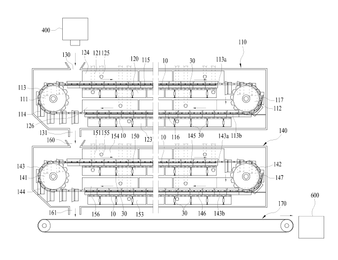
FIG. 1 is a block diagram illustrating a coal dryer
using reheat steam according to an embodiment of the present
invention;
FIG. 2 is a schematic view illustrating a front surface
of the coal dryer using reheat steam according to the
47
CA 02952211 2016-12-13
present invention;
FIG. 3 is a schematic view illustrating a side surface
the coal dryer using reheat steam according to the present
invention;
FIGS. 4 and 5 are perspective views illustrating a main
part of the the coal dryer using reheat steam, in which a
multi-stage transportation coal flattener is installed
according to the present invention;
FIG. 6 is a perspective view illustrating a
transportation coal flattener in a coal dryer using reheat
steam according to a first embodiment of the present
invention;
FIG. 7 is a side view illustrating an operation of the
transportation coal flattener according to the present
invention;
FIG. 8 is a plan view illustrating the operation of the
transportation coal flattener using reheat steam according
to the present invention;
FIGS. 9A and 93 are a front view and a rear view
illustrating the operation of the transportation coal
flattener according to the present invention;
FIG'. 10 is a perspective view illustrating a modified
example of the transportation coal flattener according to
the present invention;
48
CA 02952211 2016-12-13
FIG. 11 is a side view of FIG. 10;
FIG. 12 is a perspective view illustrating another
modified example of the transportation coal flattener
according to the present invention;
FIG,. 13 is a side view of FIG. 12;
FIG. 14 is a perspective view illustrating a
transportation coal flattener in a coal dryer using reheat
steam according to a second embodiment of the present
invention;
FIGS. 15A and 15B are a plan view and a side view
illustrating an operation of the transportation coal
flattener according to the present invention;
FIG. 16 is a side view illustrating detailed
configurations of the transportation coal flattener
according to the present invention;
FIG. 17 is a perspective view illustrating a modified
example of the transportation coal flattener according to
the present invention;
FIGS. 18A and 18B are a plan view and a side view
illustrating an operation of the transportation coal
flattener according to the present invention;
FIG. 19 is a side view illustrating detailed
configurations of the transportation coal flattener
according to the present invention;
49
CA 02952211 2016-12-13
FIGS. 20 and 21 are perspective views illustrating
another modified example of the transportation coal
flattener according to the present invention;
FIGS. 22 and 23 are perspective views illustrating a
main part of a coal dryer using reheat steam, in which a
multi-stage transportation coal flattener is installed,
according to a third embodiment of the present invention;
FIG, 24 is a perspective view illustrating another
modified example of the transportation coal flattener
according to the present invention;
FIG. 25 is a side view illustrating the operation of
the transportation coal flattener according to the present
invention;
FIGS. 26 and 27 are a front view and a plan view
illustrating the operation of the transportation coal
flattener according to the present invention;
FIGS. 28 and 29 are perspective views illustrating a
main pat of a coal dryer using reheat steam, in which a
plurality of dispersion flatteners and flatteners are
installed, according to a fourth embodiment of the present
invention;
FIG. 30 is a perspective view illustrating a dispersion
flattenei according to the present invention;
FIG. 31 is a perspective view illustrating a flattener
CA 02952211 2016-12-13
according to the present invention;
FIG. 32 is a perspective view illustrating a modified
example of the dispersion flattener according to the present
invention;
FIG. 33 is a perspective view illustrating a modified
example of the flattener according to the present invention;
FIG. 34 is a side view illustrating operations of a
dispersion flattener and a multi-stage flattener based on a
biased load of the transportation coal according to the
present invention;
FIGS. 35 and 36 are a front view and a plan view
illustrating the operations of the dispersion flattener and
the flattener according to the present invention;
FIGS. 37 and 38 are perspective views illustrating a
main part of a coal dryer using reheat steam, in which a
sorter for uniform drying of the transportation coal is
installed, according to a fifth embodiment of the present
invention;
FIG. 39 is a perspective view illustrating the sorter
according to the present invention;
FIG. 40 is a perspective view illustrating a modified
example of the sorter according to the present invention;
FIGS. 41A to 41D are front views, a side view and a
plan view illustrating an operation of the sorter for
51
CA 02952211 2016-12-13
uniform drying of the transportation coal according to the
present invention;
FIGS. 42 and 43 are perspective views illustrating a
main par ,t of a coal dryer using reheat steam, in which a
multi-stage sorter and a flattener for uniform drying of the
transportation coal are installed, according to a sixth
embodiment of the present invention;
FIG. 44 is a side view illustrating operations of the
sorter ,and the flattener for uniform drying of the
transportation coal according to the present invention;
FIGS. 45 and 46 are a front view and a plan view
illustrating operations of the sorter and the flattener for
uniform drying of the transportation coal according to the
present invention, respectively;
FIGS. 47 and 48 are perspective views illustrating a
main part of the coal dryer using reheat steam, in which the
flattener, a plurality of dividers and the dispersion
flattener are installed, according to the sixth embodiment
of the present invention;
FIG. 49 is a perspective view illustrating the divider
and the dispersion flattener according to the present
invention;
FIG. 50 is a plan view illustrating operations of the
flattener, the divider and the dispersion flattener
52
CA 02952211 2016-12-13
according to the present invention;
FIG'. 51 is a sectional view illustrating operations of
the flattener, the divider and the dispersion flattener
according to the present invention;
FIG. 52 is a perspective view illustrating a coal
residue remover in a coal dryer using reheat steam according
to a seventh embodiment of the present invention;
FIG. 53 is a perspective view illustrating an operation
of a remover for removing coal residues stuck to a transfer
plate according to the present invention;
FIG. 54 is a sectional view illustrating an operation
of a remover for removing coal residues stuck to a transfer
plate according to the present invention;
FIGS. 55 and 56 are perspective views illustrating a
main part of a coal drying dryer using reheat steam, in
which a transportation coal flattener is installed,
according to an eighth embodiment of the present invention;
FIG. 57 is an exploded perspective view illustrating a
main part of a transportation device in the coal dryer using
reheat steam according to the present invention; and
FIGS.58 and 59 are sectional views illustrating an
operation of the transportation device in the coal dryer
using reheat steam according to the present invention,
respectively.
53
CA 02952211 2016-12-13
BEST MODE FOR THE INVENTION
Hereinafter, a dispersing and flattening apparatus for
uniform drying of transportation coals in a coal dryer using
reheat steam will be described in detail with reference to
the accompanying drawings.
The present invention uniformly disperses and flatly
transfers coals while reducing loads of the coals input into
a transportation device when the coals are dried while being
transferred by using the transportation device such as a
conveyor and a transfer plate, so that a drying effect of
the coals is improved. In addition, a transportation coal
flattener is installed in a coal dryer that dries coals by
spraying high-temperature reheat steam while the coals are
transferted by inputting the coals from a fixed quantity
coal supplier that supplies pulverized coals at a fixed
quantity to a transportation device of the coal dryer.
In FIG. 1, a coal storage silo 200 is a place where
coals used for fuel of a boiler of a thermal power plant is
stored. The coals contains surface moisture and internal
moisture. In addition, the coals stored in the coal storage
silo 200 are prevented from being scattered, by periodically
spraying water. The coals stored in the coal storage silo
200 is transferred to a coal dryer 100 through a
transportation means such as a conveyor system. Here, coals
54
CA 02952211 2016-12-13
in the coal storage silo 200, from which moisture is not
removed, may be moved to and stored in a coal supply tank
300 for drying that is connected to the coal dryer. Further,
the coals stored in the coal supply tank 300 are supplied
from a fixed quantity coal supplier 400 to the coal dryer
100 at a fixed quantity. The coal dryer 100 includes a third
coal dryer 170 for drying coals that are discharged through
a first coal dryer 110 and a second coal dryer 140 that are
installed in a multi-layer. The first coal dryer 110 and the
second coal dryer 140 are configured to have approximately
the same structure. Coals that are naturally dried via the
third coal dryer 170 are temporarily stored in a dry coal
storage tank 600 and are then supplied as fuel of a boiler
of a thermal power plant 700.
In FIGS. 2 and 3, an example of the coal dryer 100 in
which transportation coal flatteners 1 are installed
according to the present invention is illustrated. The coal
dryer 100 includes a multi-stage dryer that dries coals
input from the fixed quantity coal supplier 400, that is,
the first coal dryer 110, the second coal dryer 140 that
secondarily dries the coals dried by the first coal dryer,
and the third coal dryer 170 that supplies the coals dried
by the second coal dryer to the dry coal storage tank 600
after naturally drying the coals.
The first coal dryer 110 includes a pair of first
CA 02952211 2016-12-13
driving 'sprockets 111 and a pair of first driven sprockets
112 that are fastened to each other by first chains 113 to
be spaced apart from each other by a specific distance, a
plurality of first transfer plates 114 that are hinge-
coupled between the first chains 113, a pair of first guide
rails 115 that are installed below an second upper chain 143
connected between the first driving sprockets 111 and the
first driven sprockets 112 to horizontally support the first
transfer plates 114, a pair of second guide rails 116 that
are installed below a first lower chain 113 connected
between the first driving sprockets 111 and the first driven
sprockets 112 to horizontally support the first transfer
plates 114, a first steam chamber 120 that is installed
below the first upper chain 113 to spray reheat steam
supplied by a reheater 500, a second steam chamber 123 that
is installed below the first lower chain 113 to spray the
reheat steam supplied by the reheater 500, a first flue gas
chamber 124 that is installed above the first upper chain
113 to collect flue gas, and a second flue gas chamber 126
that is installed above the first lower chain 113 to collect
flue gas.
Further, the second coal dryer 140 includes a pair of
second driving sprockets 141 and a pair of second driven
sprockets 142 that are fastened to each other by second
chains 143 to be spaced apart from each other by a specific
56
CA 02952211 2016-12-13
distance, a plurality of second transfer plates 144 that are
hinge-coupled between the second chains 143, a pair of third
guide rails 145 that are installed below a second upper
chain 143 connected between the second driving sprockets 141
and the second driven sprockets 142 to horizontally support
the second transfer plates 144, a pair of fourth guide rails
146 that are installed below a second lower chain 143
connected between the second driving sprockets 141 and the
second driven sprockets 142 to horizontally support the
second transfer plates 144, a third steam chamber 150 that
is installed below the second upper chain 143 to spray the
reheat steam supplied by the reheater 500, a fourth steam
chamber 153 that is installed below the second lower chain
143 to spray the reheat steam supplied by the reheater 500,
a third flue gas chamber 154 that is installed above the
second upper chain 143 to collect flue gas, and a fourth
flue gas chamber 156 that is installed above the second
lower chain 143 to collect flue gas.
Thus, the transportation coal flatteners 1 are fixedly
installed at front ends of the first flue gas chamber 124
and the second flue gas chamber 126 of the first coal dryer
110 and the third flue gas chamber 154 and the fourth flue
gas chamber 156 of the second coal dryer 140, respectively.
In .FIG. 4, the transportation coal flatteners 1 are
installed at upper portions of surfaces of the plurality of
57
CA 02952211 2016-12-13
first transfer plates 114 of the first coal dryer 110, which
face an upper side, that is, at a front end of the first
flue gas chamber 124 and at upper portions of surfaces of
the plurality of second transfer plates 144 of the second
coal dryer 140, which face an upper side, that is, at a
front end of the third flue gas chamber 154, at a specific
interval. In addition, opposite ends of a body 2 of the
transportation coal flattener 1 are fixedly supported at
upper ends of first guide rails 115 that horizontally
support the first transfer plates 114 and at upper ends of
the third guide rails 145 that horizontally support the
second txansfer plates 144, by a pair of fixing members 5,
respectively.
Further, in FIG. 5, the transportation coal flatteners
1 are installed at upper portions of surfaces of the
plurality of first transfer plates 114 of the first coal
dryer 110, which face an upper side, that is, at a front end
of the first flue gas chamber 126 and at upper portions of
surfaces of the plurality of second transfer plates 144 of
the second coal dryer 140, which face an upper side, that
is, at a front end of the third flue gas chamber 156, at a
specific, interval. In addition, the opposite ends of the
body 2 of the transportation coal flattener 1 are fixedly
supported at an upper end of the second guide rail 116 that
horizontally supports the first transfer plates 114 and at
58
CA 02952211 2016-12-13
an upper end of the fourth guide rail 146 by the pair of
fixing members 5, respectively.
Thus, two transportation coal flatteners 1 are
installed in the first coal dryer 110 and two transportation
coal flatteners 1 are installed in the second coal dryer
140. These are installed at a front end of the first flue
gas chamber 124 in which coals are input to upper ends of
surfaces of the first transfer plates 114 of the first coal
dryer 110 that face an upper side, at a front end of the
second flue gas chamber 126 in which coals falls from first
upper transfer plates 114 of the first coal dryer 110 to
surfaces of first lower transfer plates 114 that face an
upper side, at a front end of the third flue gas chamber 154
in which coals falls from the first lower transfer plates
114 of the first coal dryer 110 to surfaces of second upper
transfer plates 144 of the second coal dryer 140 that face
an upper side and at a front end of the fourth flue gas
chamber 156 in which coals falls from the second upper
transfer plates 144 of the second coal dryer 140 to surfaces
of second lower transfer plates 144 that face an upper side,
respectively, to disperse and flatten input and fallen piles
of coals to allow reheat steam sprayed while passing through
the first transfer plates 114 and the second transfer plates
144 to be uniformly in contact with surfaces of coal
particles, thereby more effectively drying the coals.
59
,
CA 02952211 2016-12-13
A plurality of through-holes 114a are formed in the
first transfer plates 114 such that the reheat steam sprayed
in the first steam chamber 120 and the second steam chamber
123 comes into contact with the coal particles while passing
through the first transfer plates 114. Guards 114b having a
specific height are installed at left and right sides of top
surfaces of the first transfer plates 114 such that the
piles of the input coals do not flow down to left sides or
right sides of the first transfer plates 114. The guards
114b have an approximately trapezoidal shape, an upper
portion of which is wide and a lower portion of which is
narrow. Thus, upper portions of the guards 114b of the first
transfer, plates 114, which are adjacent to each other,
overlap each other. Here, it is preferred that the guards
114b of the first transfer plates 114, which are adjacent to
each other, are installed in an approximately zigzag
direction. Further, shielding plates 114c are installed at
left and right sides of bottom surfaces of the first
transfer plates 114 such that the reheat steam sprayed in
the first steam chamber 120 and the second steam chamber 123
is not dissipated due to spraying thereof to left and right
sides of the first steam chamber 120 and the second steam
chamber 123, respectively.
Further, a plurality of through-holes 144a are formed
in the second transfer plates 144 such that reheat steam
,
CA 02952211 2016-12-13
sprayed in the third steam chamber 150 and the fourth steam
chamber 153 comes into contact with the coal particles while
passing through the second transfer plates 144. Guards 144b
having a specific height are installed at left and right
sides of top surfaces of the second transfer plates 144 such
that the piles of the input coals do not flow down to left
sides or right sides of the second transfer plates 144. The
guides 144b have an approximately trapezoidal shape, an
upper portion of which is wide and a lower portion of which
is narrow. Thus, upper portions of the guards 144b of the
second transfer plates 144, which are adjacent to each
other, overlap each other. Here, it is preferred that the
guards 144b of the second transfer plates 144, which are
adjacent to each other, are installed in an approximately
zigzag direction. Further, shielding plates 144c are
installed at left and right sides of bottom surfaces of the
second transfer plates 144 such that the reheat steam
sprayed in the third steam chamber 150 and the fourth steam
chamber 153 is not dissipated due to spraying thereof to
left and right sides of the third steam chamber 150 and the
fourth steam chamber 153, respectively.
A first embodiment of the dispersing flattening
apparatus for uniform drying of transportation coals in a
coal dryer using reheat steam according to the present
invention will be described in detail with reference to
61
CA 02952211 2016-12-13
FIGS. 6 to 13.
In FIG. 6, a transportation coal flattener 1 includes a
column-shaped body 2. A surface of the body 2, through which
coals may be uniformly dispersed on a transportation device,
may be formed to have a polygonal shape or an elliptical
shape. Further, a division boss 3 that divides and disperses
a center of piles of coals input from a fixed quantity coal
supplier to a transportation device into left and right
parts protrudes from a center of a front surface of the body
2. The division boss 3 has an approximately triangular
column shape and has an edge having an intersection line in
front of the body 2. Thus, when the piles of the coals comes
into contact with the division boss 3, coal particles are
divided into opposite left and right sides by the division
boss 3. When coals are input onto the transportation device,
the coals are stacked in approximately an arc shape. Thus,
the piles of the coals that are stacked in an arc shape have
a density that is high on a center thereof and becomes lower
as it goes to front, rear, left and right sides. Therefore,
the division boss 3 performs a function of dividing and
dispersing the center of the piles of the coals into left
and right parts.
Opposite ends of the body 2 having the division boss 3
that protrudes therefrom are fixedly supported by a pair of
fixing members that are fixed to one side of the
62
CA 02952211 2016-12-13
transportation device. In addition, transportation coal
flatteners 1 are installed on the transportation device to
be spaced apart from each other at a specific interval.
Further, the transportation coal flattener 1 flattens the
piles of the coals, which are transferred by the
transportation device, at a specific height, and thus,
allows reheat steam sprayed while passing through the
transportation device to uniformly come into contact with
surfaces of the coal particles.
In FIGS. 7 and 8, coals C that are input onto first
transfer plates 114 and second transfer plates 144 are
flattened while passing through a bottom surface of the flat
body 2 after being dispersed into left and right sides while
passing through the division boss 3 of the transportation
coal flattener 1.
In addition, In FIG. 9A, the coals C that are input or
fall onto the first transfer plates 114 and the second
transfer plates 144 are stacked approximately in an arc
shape. Here, the coals C that are stacked in an arc shape
have a density that is high on a center thereof and becomes
lower as it goes to front, rear, left and right sides. Thus,
when the transferred coals C comes into contact with the
division boss 3, a center of the coals C is divided into
opposite left and right sides so that coal particles are
dispersed. In FIG. 9B, the coals C that are dispersed in
63
CA 02952211 2016-12-13
this way are flatly arranged on surfaces of the first
transfer plates 114 and the second transfer plates 144,
which face an upper side, while passing through the
transportation coal flattener 1.
As another embodiment according to the present
invention, in FIGS. 10 and 11, the transportation coal
flattener 1 has a plurality of wedges 4 that are spaced
apart from each other at a specific interval to protrude
from a bottom surface of the body 2. That is, after being
dispersed into left and right sides while passing through
the division boss 1 of the transportation coal flattener 1,
the coals C pass through the wedges 4 that protrude from the
bottom surface of the body 2 so that the density of the
coals 3 are dispersed, and thus more uniform flattening may
be achieved.
As yet another embodiment according to the present
invention, in FIGS. 12 and 13, the bottom surface of the
body 2 of the transportation coal flattener 1 is formed in
an inclined surface 6 having a shape of which a thickness
becomes thicker as it goes from an end of a blade of the
division boss 3 to a rear surface of the body 2 and which is
inclined at a specific slope. That is, after being dispersed
into left and right sides while passing through the division
boss 3 of the transportation coal flattener 1, the coals C
pass through the division boss 3 and the inclined surface 6
64
CA 02952211 2016-12-13
that is inclined on the bottom surface of the body 2 at a
specific, angle so that the density of the coals 3 are
dispersed, and thus uniform flattening may be maintained.
Further, in the present invention, the bottom surface
of the body 2 is formed to have a shape of which a thickness
becomes thicker as it goes from the end of the blade of the
division, boss 3 to a rear surface of the body 2 and which is
inclined at a specific slope and, at the same time the
plurality of wedges 4 are spaced apart from each other at a
specific interval to protrude from the bottom surface of the
body 2.
Next, a second embodiment of the dispersing flattening
apparatus for uniform drying of transportation coals in a
coal dryer using reheat steam according to the present
invention will be described in detail with reference to
FIGS. 14 to 21.
In FIG. 14, a transportation coal flattener 1 includes
a column-shaped body 2. A surface of the body 2, through
which coals may be uniformly dispersed on a transportation
device, may be formed to have a polygonal shape or an
elliptical shape. Further, a division boss 3 that divides
and disperses a center of piles of coals input from a fixed
quantity coal supplier to a transportation device into left
and right parts protrudes from a center of a front surface
of the body 2. The division boss 3 has an approximately
CA 02952211 2016-12-13
triangular column shape and has an edge having an
intersection line in front of the body 2. Thus, when the
piles of the coals comes into contact with the division boss
3, coal particles are divided into opposite left and right
sides by, the division boss 3. When coals are input onto the
transportation device, the coals are stacked in
approximately an arc shape. Thus, the piles of the coals
that are stacked in an arc shape have a density that is high
on a center thereof and becomes lower as it goes to front,
rear, left and right sides. Therefore, the division boss 3
performs a function of dividing and dispersing the center of
the piles of the coals into left and right parts.
Opposite ends of the body 2 having the division boss 3
that protrudes therefrom are fixedly supported by a pair of
fixing members that are fixed to one side of the
transportation device. In addition, transportation coal
flatteners I are installed on the transportation device to
be spaced apart from each other at a specific interval.
Further, the transportation coal flattener 1 flattens the
piles of the coals, which are transferred by the
transportation device, at a specific height, and thus,
allows reheat steam sprayed while passing through the
transportation device to uniformly come into contact with
surfaces of the coal particles.
In addition, in FIGS. 15A and 15B, a dispersion boss 7
66
CA 02952211 2016-12-13
protrudes from a lower edge, that is, front and opposite
sides of the division boss 3. The dispersion boss 7 has an
edge 8 that protrudes from a front side of a lower edge of
the division boss 3 and a blade 9 that protrudes from the
edge 8 to opposite surfaces of the lower edge of the
division boss 3. Inclined surfaces having a specific slope,
which become wider as they go from above to below, are
formed from the edge 8 to the blade 9 of the dispersion boss
7.
The dispersion boss 7 crosses a central portion of the
piles of the coals that are transferred by the
transportation device, by the edge 8, to divide the central
portion having a high density. The dispersion boss 7 allows
the coals, which flow down after the piles of the coals
divided by the edge 8 and the division boss 3 are dispersed
into opposite sides along the division boss 3, to flow down
to front sides of the inclined surfaces on opposite sides
thereof so as to disperse the piles of the coals at an
uniform density and uniformly spread the piles of the coals
on a surface of the transportation device.
In FIG. 16, the dispersion boss 7 including the edge 8,
the blade 9 and the inclined surfaces is illustrated with
reference to an intersection line in which a surface and a
surface meet each other and an intersection point in which a
line and a line meet each other.
67
CA 02952211 2016-12-13
That is, a first intersection line al is a line in
which opposite surfaces of the division boss 3 meet each
other on the front surface thereof, a second intersection
line a2 is a line in which the opposite inclined surfaces 9
of the dispersion boss 7 meet each other, a third
intersection line a3 is a line in which a side surface of
the division boss 3 and the inclined surfaces 9 of the
dispersion boss 7 meet each other, a fourth intersection
line a4 is a line corresponding to a blade 13 in which the
bottom surface and the edge of the dispersion boss 7 meet
each other, and a fifth intersection line a5 is a line in
which the side surface of the division boss 3 and the body 2
meet each other. Further, a first intersection point bl is a
point at which the first intersection line al and the second
intersection line a2 meet each other, a second intersection
point b2 is a point at which the second intersection line a2
and the fourth intersection line a4 meet each other, and a
third intersection point b3 is a point at which the third
intersection line a3, the fourth intersection line a4 and
the fifth intersection line a5 meet each other.
Thus, the dispersion boss 7 that protrudes from a lower
edge of the division boss 3 of the flatter 1 corresponds to
a three-dimensional portion that is formed by contacting the
first intersection point bl in which the second intersection
line a2 and the third intersection line a3 meet each other,
68
CA 02952211 2016-12-13
the second intersection point b2 in which the second
intersection line a2 and the fourth intersection line a4
meet each other and the third intersection point b3 in which
the third intersection line a3 and the fourth intersection
line a4 meet each other.
Further, as another modified example of the present
invention, in FIGS. 17 and 18, a dispersion boss 7 protrudes
from a lower edge, that is, front and opposite sides of the
division boss 3. The dispersion boss 7 has an edge 8 that
protrudes from a front side of a lower edge of the division
boss 3 and a blade 9 that protrudes from the edge 8 to
opposite surfaces of the lower edge of the division boss 3.
Inclined surfaces having a specific slope, which become
wider as they go from the edge 8 to the blade 9 of the
dispersion boss 7, are formed. Further, the dispersion boss
7 has inclined surfaces having a specific width, which
extend from the edge 8 to the body 2.
The dispersion boss 7 crosses a central portion of the
piles of the coals that are transferred by the
transportation device, by the edge 8, to divide the central
portion having a high density. The dispersion boss 7 allows
coals, which flow down after the piles of the coals divided
by the edge 8 and the division boss 3 are dispersed into
opposite sides along the division boss 3, to flow down to
front sides of the inclined surfaces on opposite sides so as
69
CA 02952211 2016-12-13
to disperse the piles of the coals at a uniform density and
uniformly spread the piles of the coals on a surface of the
transportation device.
In addition, in FIG. 19, the dispersion boss 7
including the edge 8, the blade 9 and the inclined surfaces
is illustrated with reference to an intersection line in
which a surface and a surface meet each other and an
intersection point in which a line and a line meet each
other. That is, the dispersion boss 7 corresponds to a
portion where the third intersection line a3 and the fourth
intersection line a4 are formed parallel to each other side
by side. That is, a first intersection line al is a line in
which opposite surfaces of the division boss 3 meet each
other on the front surface thereof, a second intersection
line a2 is a line in which the opposite inclined surfaces 9
of the dispersion boss 7 meet each other, a third
intersection line a3 is a line in which the side surface of
the division boss 3 and the inclined surfaces 9 of the
dispersion boss 7 meet each other, a fourth intersection
line a4 is a line corresponding to a blade 13 in which the
bottom surface and the edge of the dispersion boss 7 meet
each other, and a fifth intersection line a5 is a line in
which a side surface of the division boss 3 and the body 2
meet each other. Further, a first intersection point bl is a
point at which the first intersection line al and the second
CA 02952211 2016-12-13
intersection line a2 meet each other, a second intersection
point b2 is a point at which the second intersection line a2
and the fourth intersection line a4 meet each other, and a
third intersection point b3 is a point at which the fourth
intersection line a4 and the fifth intersection line a5 and
a fourth intersection point b4 is a point at which the third
intersection line a3 and the fifth intersection line a5 meet
each other. Here, the third intersection line a3 and the
fourth intersection line a4 are parallel to each other side
by side.
Thus, the dispersion boss 7 that protrudes from a lower
edge of the division boss 3 of the flatter 1 corresponds to
a three-dimensional portion that is formed by contacting the
first intersection point bl in which the second intersection
line a2 and the third intersection line a3 meet each other,
the second intersection point b2 in which the second
intersection line a2 and the fourth intersection line a4
meet each other, the third intersection point b3 in which
the fourth intersection line a4 and the fifth intersection
line a5 meet each other and the fourth intersection point b4
in which the third intersection line a3 and the fifth
intersection line a5 meet each other.
Coals C that are input onto surfaces of the first
transfer plates 114 and the second transfer plates 144 of
the coal dryer are flattened as the coals are divided into
71
CA 02952211 2016-12-13
left and right sides while passing through the division boss
3 of the transportation coal flattener 1 and the divided
coals are uniformly dispersed along the dispersion boss 7
and are then flattened while passing through the flat body
2. In addition, the coals C that are input or fall onto the
first transfer plates 114 and the second transfer plates 144
are stacked approximately in an arc shape. Here, the coals C
that are stacked in an arc shape have a density that is high
on a center thereof and becomes lower as it goes to front,
rear, left and right sides. Thus, when the transferred coals
C comes into contact with the division boss 3 and the edge 8
of the dispersion boss 7, a center of the coals C is divided
into opposite left and right sides so that coal particles
are dispersed. Further, the dispersion boss 7 more uniformly
disperses the coal particles to make a density of the piles
of the coals more uniform. The coals C that are dispersed in
this way are flatly arranged on surfaces of the first
transfer plates 114 and the second transfer plates 144,
which face an upper side, by passing through the
transportation coal flattener 1.
As another modified example of the present invention,
in FIG. 20, a plurality of dispersion bosses 7 are
vertically formed on the side surface of the division boss
3. This is for achieving flattening at a uniform density by
more effectively dispersing the coals C that are input onto
72
CA 02952211 2016-12-13
the surfaces of the first transfer plates 114 and the second
transfer plates 144, which face an upper side, by the
plurality of dispersion bosses 7 formed on opposite surface
of the division boss 3. That is, a center portion of the
coals C that are input onto the surfaces of the first
transfer plates 114 and the second transfer plates 144,
which face an upper side, in an arc shape is divided by
first dispersion bosses 7 that are formed on opposite sides
of a central portion of the division boss 3 of the flattener
1 and second dispersion bosses 7 that are formed on opposite
sides of a lower portion of the division boss 3 and the
divided coals C are uniformly dispersed and flattened by
edges, blades and inclined surfaces of the first dispersion
boss 7 and the second dispersion boss 7. In FIG. 15, the
inclined surfaces of each dispersion boss 7 has an
approximately triangular shape that is obtained by
connecting the first intersection point, the second
intersection point and the third intersection point to each
other by intersection lines therebetween, when viewed from a
side surface.
In addition, in FIG. 21, the inclined surfaces of the
first dispersion boss 7 and the second dispersion boss 7
have an approximately quadrangular shape that is obtained by
connecting the first intersection point, the second
intersection point, the third intersection point and the
73
CA 02952211 2016-12-13
fourth intersection point to each other, when viewed from a
side surface.
Next, a third embodiment of the dispersing flattening
apparatus for uniform drying of transportation coals in a
coal dryer using reheat steam according to the present
invention will be described in detail with reference to
FIGS. 22 to 27.
In FIGS. 22 and 23, a plurality of flatteners 10, 20,
30 and 40 are installed at front ends of the first flue gas
chamber 124 and the second flue gas chamber 126 to disperse
and flatten piles of coals C that fall from the first upper
transfer plates 114 onto the surface of the first lower
transfer plates 114. Further, the plurality of flatteners
10, 20, 30 and 40 are installed at front ends of the third
flue gas chamber 154 and the fourth flue gas chamber 156 to
disperse' and flatten the transferred piles of the coals C.
In addition, the plurality of flatteners 10, 20, 30 and 40
may be also installed inside the first flue gas chamber 124,
the second flue gas chamber 126, the third flue gas chamber
154 and the fourth flue gas chamber 156. Thus, the plurality
of flatteners 10, 20, 30 and 40 are installed in the first
flue gas chamber 124, the second flue gas chamber 126, the
third flue gas chamber 154 and the fourth flue gas chamber
156 to disperse and flatten loads of the input and fallen
piles of the coals so as to allow reheat steam sprayed while
74
CA 02952211 2016-12-13
passing through the first transfer plates 114 and the second
transfer plates 144 to uniformly come into contact with
surfaces of coal particles, thereby more effectively drying
the coals.
In FIG. 24, each of the flatteners 10, 20, 30 and 40
further has a dispersion boss 7 that has an edge 8 which
protrudes from a front side of a lower edge of a division
boss and a blade 9 which protrudes from opposite side
surfaces of the lower edge of the division boss, and that
has inclined surfaces having a specific slope, which become
wider as they go from the edge 8 to the blade 9 from above
to below.
The dispersion boss 7 has the edge 8 that protrudes
from the front side of the lower edge of the division boss
12 and the blade 9 that protrudes from the edge 8 to
opposite side surfaces of the lower edge of the division
boss 12. Inclined surfaces having a specific slope, which
become wider as they go from the edge 8 to the blade 9 of
the dispersion boss 7, are formed. The dispersion boss 7
crosses a central portion of the piles of the coals that are
transferred by the transportation device, by the edge 8, to
divide the central portion having a high density. The
dispersion boss 7 allows coals, which flow down after the
piles of the coals divided by an edge 11 and the division
boss 12 are dispersed into opposite sides along the division
CA 02952211 2016-12-13
boss 12, to flow down to front sides of the inclined
surfaces on opposite sides so as to disperse the piles of
the coals at a uniform density and uniformly spread the
piles of the coals on a surface of the transportation
device.
In FIG. 25, the plurality of flatters 10, 20, 30 and 40
flatten the piles of the coals C that are transferred on
surfaces of the first transfer plates 114, which faces an
upper side, to be increasingly lowered at a specific height
interval, so as to reduce loads of the piles of the
transferred coals C and allow the reheat steam sprayed while
passing through the first transfer plates 114 to uniformly
come into contact with surfaces of coal particles as well.
In addition, in FIGS. 26A and 27A, the piles of the
coals C that are input from a dust reducer 1 to the surfaces
of the first transfer plates 114 and are transferred have an
approximately circular arc shape. The piles of the coals C
are dispersed into opposite sides by the division boss 12
while an upper portion thereof is flattened, while the piles
pass through the first flattener 10. Further, in FIGS. 26B
and 27B, the piles of the coals C flattened while passing
through the first flattener 10 are dispersed into opposite
sides by a division boss 22 while an upper portion thereof
is flattened, while the piles pass through the second
flattener 20. Further, in FIGS. 26C and 270, the piles of
76
CA 02952211 2016-12-13
,
the coals C flattened while passing through the second
flattener 20 are dispersed into opposite sides by a division
boss 32 while an upper portion thereof is flattened, while
the piles pass through the third flattener 30. Further, in
FIGS. 26D and 27D, the piles of the coals C flattened while
passing through the third flattener 30 are dispersed into
opposite sides by a division boss 42 while an upper portion
thereof is flattened, while the piles pass through the
fourth flattener 40. Thus, the piles of the coals C having a
circular' arc shape are flattened to have approximately the
same thickness as that of the surfaces of the first transfer
plates 114 while passing through the first flattener 10 to
the fourth flattener 40. Thus, the piles of the coals C
having a specific volume and a specific weight, which are
input from the dust reducer 1, are dispersed and flattened
in a reduced load while passing through the first flattener
to the fourth flattener 40.
Next, a fourth embodiment of the dispersing flattening
apparatus for uniform drying of transportation coals in a
coal dryer using reheat steam according to the present
invention will be described in detail with reference to
FIGS. 28 to 36.
Next, a fourth embodiment of the dispersing flattening
apparatus for uniform drying of transportation coals in a
coal dryer using reheat steam according to the present
77
CA 02952211 2016-12-13
invention will be described in detail with reference to
FIGS. 28 to 36.
In FIGS. 28 and 29, a first dispersion flattener 1010,
a second dispersion flattener 1020 and a flattener 1030 are
installed at front ends of the first flue gas chamber 124
and the second flue gas chamber 126 to disperse and flatten
piles of coals C that fall from the first upper transfer
plates 114 to the surfaces of the first lower transfer
plates 114. Further, the first dispersion flattener 1010,
the second dispersion flattener 1020 and the flattener 1030
are installed at front ends of the third flue gas chamber
154 and the fourth flue gas chamber 156 to disperse and
flatten the transferred piles of the coals C. In addition,
the first dispersion flattener 1010, the second dispersion
flattener 1020 and the flattener 1030 may be also installed
inside the first flue gas chamber 124, the second flue gas
chamber 126, the third flue gas chamber 154 and the fourth
flue gas chamber 156. Thus, the first dispersion flattener
1010, the second dispersion flattener 1020 and the flattener
1030 are installed in the first flue gas chamber 124, the
second flue gas chamber 126, the third flue gas chamber 154
and the fourth flue gas chamber 156 to disperse and flatten
loads of, the input and fallen piles of the coals so as to
allow reheat steam sprayed while passing through the first
transfer plates 114 and the second transfer plates 144 to be
78
CA 02952211 2016-12-13
uniformly in contact with surfaces of coal particles,
thereby more effectively drying the coals.
In FIG. 30, the dispersion flattener 1010 includes an
approximately triangular column-shaped body 1011 such that a
protruding division boss 1012 is formed at a center of a
front surface of the body 1011. Further, a fixing shaft 1014
having a specific length is fixed to a center of a upper
flat surface of the body 1011 and a restoration member 1013
that horizontally and elastically supports the body 1011
with respect to the fixing shaft 1014 is formed between the
fixing shaft 1014 and the body 1011. A spring having
elasticity, for example, a compression spring, a leaf spring
or the like may be applied to the restoration member 1013.
The restoration member 1013 is fixed to the fixing shaft
1014 on one side thereof and is fixed to the body 1011 on
the other side thereof so that the body 1011 can be
transversely rotated and restored about the fixing shaft
1014. Further, a fixing member 1015 is coupled to an upper
end of the fixing shaft 1014 to fixedly support the fixing
shaft 1014. Further, the fixing member 1015 is fixedly
installed on one side of the transportation device, for
example, to the first guide rails 115 to fixedly support the
body 1011 via the fixing shaft 1014.
The dispersion flatteners are classified into the first
dispersion flattener 1010 and the second dispersion
79
CA 02952211 2016-12-13
flattener 1020 and the first dispersion flattener 1010 and
the second dispersion flattener 1020 are installed on the
first transfer plates 114 at a specific interval..
In FIG. 31, the flattener 1030 includes a column-shaped
body 1031, a dispersion boss 1032 that protrudes from a
center of a front surface of the body, and a pair of fixing
members 1033 that fixedly support opposite ends of the body
1031. That is, the flattener 1030 includes a column-shaped
body 1031. A surface of the body 1031, through which coals
may be uniformly dispersed on the transportation device, may
be formed to have a polygonal shape or an elliptical shape.
Further, the division boss 1032 that divides and disperses a
center of piles of coals transferred after passing through
the second dispersion flattener 1020 into left and right
parts protrudes from a center of the front surface of the
body 1031. The division boss 1032 has an approximately
triangular column shape and has an edge having an
intersection line in front of the body 1031. Thus, when the
piles of the coals come into contact with the division boss
1032, coal particles are divided into opposite left and
right sides by the division boss 1032. Thus, the division
boss 1032 performs a function of dividing and dispersing the
center of the piles of the coals into left and right parts
and flattening the piles of the coals as well.
Opposite ends of the body 1031 having the division boss
CA 02952211 2016-12-13
1032 that protrudes therefrom are fixedly supported by the
pair of fixing members 1033 that are fixed to one side of
the transportation device. In addition, flatteners 1030 is
are installed on the transportation device at a specific
interval. Further, the flattener 1030 flattens the piles of
the coals, which are transferred by the transportation
device, at a specific height, and thus, allows reheat steam
sprayed .while passing through the transportation device to
uniformly come into contact with surfaces of the coal
particles.
Pair of transportation coal guide plates 1040 and 1050
are installed toward insides of the first transfer plates
144 at a specific angle such that the piles of the coals
that are transferred on surfaces of the first transfer
plates 114 are collected on insides, that is, central
portion of the surfaces of the first transfer plates 114.
The first transportation coal guide plates 1040 are
installed between the first dispersion flattener 1010 and
the second dispersion flattener 1020, that is, on a rear
side of the first dispersion flattener 1010, and the second
transportation coal guide plates 1050 are installed between
the second dispersion flattener 1020 and the flattener 1030,
that is, on a rear side of the second dispersion flattener
1020. The first transportation coal guide plates 1040 and
the second transportation coal guide plates 1050 are
81
CA 02952211 2016-12-13
,
installed toward the insides of the first transfer plates
114 at a specific angle such that a length of the first
transportation coal guide plates 1040 is larger than a
length of the second transportation coal guide plate 1050 or
an installation angle of the first transportation coal guide
plates 1040, which corresponds to a transfer direction of
piles of coals, is larger than an installation angle of the
second transportation coal guide plates 1050. Upper ends of
the first transportation coal guide plates 1040 and the
second transportation coal guide plates 1050 are fixedly
supported by support members 1041 and 1051 fixed to the
first guide rails 115, respectively.
Further, it is also preferred that a pair of
transportation coal guide plates are installed in front of
the first dispersion flattener 1010 so that flow of the
transferred piles of the coals is collected to inner sides
of the surfaces of the first transfer plates 114.
Further, in FIG. 32, each of the first dispersion
flattener 1010 and the second dispersion flattener 1020
further has a dispersion boss 1060 that has an edge 1061
which protrudes from a front side of a lower edge of a
division boss and a blade 1062 which protrudes from opposite
side surfaces of the lower edge of the division boss, and
that has inclined surfaces having a specific slope, which
become wider as they go from the edge 1061 to the blade 1062
82
CA 02952211 2016-12-13
from above to below. Further, in FIG. 33, the flattener
further ,has a dispersion boss 1060 that has an edge 1061
which protrudes from a front side of a lower edge of a
division boss and a blade 1062 which protrudes from opposite
side surfaces of the lower edge of the division boss and
that has inclined surfaces having a specific slope, which
become wider as they go from the edge 1061 to the blade 1062
from above to below.
The dispersion boss 1060 has the edge 1061 that
protrudes from the front side of the lower edge of the
division boss 1012 and the blade 1062 that protrudes from
the edge, 1061 to opposite side surfaces of the lower edge of
the division boss 1012. Inclined surfaces having a specific
slope, which become wider as they go from the edge 1061 to
the blade 1062 of the dispersion boss 1060, are formed. The
dispersion boss 1060 crosses a central portion of the piles
of the coals that are transferred by the transportation
device, by the edge 1061, to divide the central portion
having a high density. The dispersion boss 1060 allows
coals, which flow down after the piles of the coals divided
by the edge 1011 and the division boss 1012 are dispersed
into opposite sides along the division boss 1012, to flow
down to front sides of the inclined surfaces on opposite
sides so as to disperse the piles of the coals at a uniform
density and uniformly spread the piles of the coals on a
83
CA 02952211 2016-12-13
surface of the transportation device.
Meanwhile, in FIG. 34, the first dispersion flattener
1010, the second dispersion flattener 1020 and the flattener
1030 are installed to have specific height steps from the
surfaces, of the first transfer plates 114 at a specific
interval to become lower as they go from front to rear. That
is, they are installed such that a bottom surface of the
first dispersion flattener 1010 is lower than a bottom
surface of the second dispersion flattener 1020 and a bottom
surface ,of the flattener 1030 is lower than the second
dispersion flattener 1020. Thus, the first dispersion
flattener 1010 and the second dispersion flattener 1020
uniformly disperse loads of the piles of the coals C that
are transferred on surfaces of the first transfer plates
114, which face an upper side while neither being biased to
any one side nor having irregular heights and flatten the
loads to gradually become lower at a specific height
interval as well. Further, the flattener 1030 more lower and
uniformly flattens the piles of the coals C that has passed
through the second dispersion flattener 1020 to allow reheat
steam sprayed while passing through the first transfer
plates 114 to uniformly come into contact with surfaces of
coal particles.
In addition, in FIGS. 35A and 36A, the piles of the
coals C that are input from the dust reducer 1 to the
84
CA 02952211 2016-12-13
surfaces of the first transfer plates 114 and are
transferred have an approximately circular arc shape but may
be formed to be biased to any one side or have irregular
heights. Here, when the piles of the coals C are biased to
any one side, the first dispersion flattener 1010 is rotated
by loads of the piles of the biased coals C while dividing
and dispersing the piles of the coals C by the division boss
1012. The body 1011 that is elastically supported at the
fixing shaft 1014 by the restoration member 1013 is rotated
to a side where the loads of the piles of the coals C are
large. While the body 1011 is rotated and supported by
elasticity of the restoration member 1013, the piles of the
coals C are transferred while passing through the body 1011
of the first dispersion flattener 1010. Thus, the division
boss 1012 faces a side where the loads of the piles of the
coals C are large so as to effectively divide and disperse a
center of the piles of the biased and transferred coals C.
In addition, because positions to which the transferred
piles of the coals C are biased may be different, the piles
of the coals C are dispersed and flattened by the division
boss 1012 toward the side where the loads are large by
elasticity of the restoration member 1013, when the loads
are changed. Further, because the piles of the coals C that
has passed through the first dispersion flattener 1010 may
be irregularly dispersed on the surfaces of the first
transfer plates 114, the pair of first transportation coal
CA 02952211 2016-12-13
guide plates 1040 collect the piles of the coals C to inner
sides of the first transfer plates 114. Thus, the piles of
the coals C that have a biased load are dispersed by the
first dispersion flattener 1010 and are then collected at a
specific load and a specific height by the first
transportation coal guide plates 1040.
Further, in FIGS. 35B and 36B, the second dispersion
flattener 1020 secondarily disperses and flattens the loads
of the piles of the coals C that have passed through the
first transportation coal guide plates 1040. Here, the
second dispersion flattener 1020 disperses and flattens the
piles of the coals C at a position of a bottom surface that
is further lower than the first dispersion flattener 1010.
The transferred piles of the coals C having biased loads are
divided and dispersed by also the second dispersion
flattener 1020 and are then collected to the inner sides of
the first transfer plates 114 through the second
transportation coal guide plates 1050. The second
transportation coal guide plates 1050 has a length smaller
than that of the first transportation coal guide plates 1040
or has an inclination angle gentler than that of the first
transportation coal guide plates 1040, which corresponds to
the transferred piles of the coals C, so as to more widely
disperse the piles of the coals C on the surfaces of the
first transfer plates 114.
86
CA 02952211 2016-12-13
Further, in FIGS. 35C and 36C, the flattener 1030
further disperses and flattens the piles of the coals C that
have passed through the second transportation coal guide
plates 1050. Here, the flattener 1030 disperses and flattens
the piles of the coals C at a position of a bottom surface
that is further lower than the second dispersion flattener
1020. Thus, the piles of the coals C that have passed
through the flattener 1030 are transferred while being
uniformly dispersed and distributed on the surfaces of the
first transfer plates 114 with few change in the density
thereof at approximately the same thickness. Therefore, the
piles of the coals C that are input from the dust reducer
1010 and have a specific volume, a specific weight and
irregular and biased loads are dispersed and flattened while
passing through the first dispersion flattener 1010, the
second dispersion flattener 1020 and the flattener 1030 and
the reheat steam sprayed while passing through the first
transfer plates 114 uniformly comes into contact with
surfaces of coal particles, thereby more effectively drying
the coals.
Next, a fifth embodiment of the dispersing flattening
apparatus for uniform drying of transportation coals in a
coal dryer using reheat steam according to the present
invention will be described in detail with reference to
FIGS. 37 to 41.
87
CA 02952211 2016-12-13
In FIGS. 37 and 38, sorters 2010 may be installed at
front ends of the first flue gas chamber 124 and the second
flue gas chamber 126 to disperse and flatten the piles of
the coals C that fall from the first upper transfer plates
114 onto the surfaces of the first lower transfer plates
114. Further, the sorters 2010 may be installed at front
ends of ,the third flue gas chamber 154 and the fourth flue
gas chamber 156 to disperse and flatten the transferred
piles of the coals C. In addition, one or more sorters 2010
may be also installed inside the first flue gas chamber 124,
the second flue gas chamber 126, the third flue gas chamber
154 and ,the fourth flue gas chamber 156. Thus, the sorters
2010 are installed in the first flue gas chamber 124, the
second flue gas chamber 126, the third flue gas chamber 154
and the fourth flue gas chamber 156 to disperse and equalize
loads and a density of the input and fallen piles of the
coals so as to allow the reheat steam sprayed while passing
through the first transfer plates 114 and the second
transfer plates 144 to be uniformly in contact with surfaces
of coal particles, thereby more effectively drying the
coals.
In FIG. 39, each sorter 2010 is obtained by integrally
coupling a rising plate 2011 that has a slope that rises at
a specific angle as it goes from front to rear and a
lowering plate 2012 that is bonded to an end of the rising
88
CA 02952211 2016-12-13
plate and has a slope that is lowered at a specific angle as
it rearward goes. A plurality of first through-holes 2013
are horizontally formed in the rising plate 2011 at a
specific internal to have a specific length. Further, the
sorter i in which the rising plate 2011 and the lowering
plate 2012 are integrally coupled to each other are fixedly
supported by a pair of fixing members 2015 on opposite sides
thereof, respectively. One fixing member 2015 is coupled to
a side surface on which the rising plate 2011 and the
lowering plate 2012 are bonded to each other and the other
fixing member 2015 is fixed to a first guide rail 115.
In addition, the sorter 2010 performs sorting that
horizontally disperses the density of piles of coals that
are transferred on the surfaces of the first transfer plates
114, which face an upper side, and uniformly equalizes the
density. One or more sorters 2010 may be installed at a
specific interval.
In FIG. 40, a plurality of second through-holes 2014
are horizontally formed on the lowering plate 2012 of the
sorter 2010 at a specific interval to have a specific width.
The second through-holes 2014 may be vertically formed on
the lowering plate 2012. Further, the first through-holes
2013 formed on the rising plate 2011 may be horizontally
formed. Thus, all the through-holes formed on the rising
plate 2011 and the lowering plate 2012 may be formed
89
CA 02952211 2016-12-13
vertically or horizontally or may be formed selectively in a
vertical direction or in a horizontal direction.
Further, a flattening member 2016 having elasticity is
coupled to a longitudinal cross-section of the lowering
plate 2012 of the sorter 2010. The flattening member 2016
may be formed of a material having elasticity such as
synthetic resin and rubber to flatten irregularly
transferred coals.
In FIGS. 41A to 41C, the piles of the coals C that are
input from the dust reducer 1 to the surfaces of the first
transfer plates 114 and are transferred have an
approximately circular arc shape but may be formed to be
biased to any one side or have irregular heights. Further, a
density of the transferred piles of the coals C becomes high
at a central portion and a lower portion thereof by gravity.
To this end, in the piles of the coals C, the reheat steam
sprayed from bottom surfaces of the first transfer plates
114 is 'not uniformly input into coal particles so that
efficiency in drying coals may be reduced. Here, the piles
of the coals C transferred by the first transfer plates 114
are horizontally separated while passing through a lower
portion of the rising plate 2011 of the sorter 2010. The
separated piles of the coals C are raised along a surface of
the rising plate 2011. The piles of the coals C that are
raised to the surface of the rising plate 2011 are
CA 02952211 2016-12-13
introduced to a lower side of the rising plate 2011 through
the first through-holes 2013 or climb over the rising plate
20111 to be transferred to a surface of the lowering plate
12. The piles of the coals C that are lowered to the surface
of the lowering plate 12 are introduced to a lower side of
the lowering plate 2012 through the second through-holes
2014 or are input onto piles of coals C that pass by the
surface of the lowering plate 2012 and pass through a bottom
surface of the lowering plate 2012.
When a bottom surface of the rising plate 2011 or a
bottom surface of the lowering plate 2012 of the sorter 2010
is installed almost adjacent to the surfaces of the first
transfer plates 114, the piles of the coals C that
transferred by the first transfer plates 114 are not united
by passing through the sorter 2010 and are thus transferred
in a state in which loads or a density of the piles of the
coals C are dispersed and equalized. Thus, the sorter 2010
uniformly mixes the transferred piles of the coals C,
thereby maximizing drying efficiency.
Next, a sixth embodiment of the dispersing flattening
apparatu for uniform drying of transportation coals in a
coal dryer using reheat steam according to the present
invention will be described in detail with reference to
FIGS. 42 to 46.
In FIGS. 42 and 43, a first sorter 3010, a first
91
CA 02952211 2016-12-13
flattener 3020, a second sorter 3020 and a second flattener
3040 are installed at front ends of the first flue gas
chamber 124 and the second flue gas chamber 126 to disperse
and flatten piles of coals C that fall from the first upper
transfer plates 114 to the surfaces of the first lower
transfer plates 114. Further, the sorter 3010, the first
flattener 3030, the second sorter 3020 and the second
flattener 3040 are installed at front ends of the third flue
gas chaMber 154 and the fourth flue gas chamber 156 to
disperse and flatten the transferred piles of the coals C.
In addition, the sorter 3010, the first flattener 3030, the
second sorter 3020 and the second flattener 3040 may be also
installed inside the first flue gas chamber 124, the second
flue gas. chamber 126, the third flue gas chamber 154 and the
fourth flue gas chamber 156. Thus, the first sorter 3010,
the first flattener 3030, the second sorter 3020 and the
second flattener 3040 are installed in the first flue gas
chamber 124, the second flue gas chamber 126, the third flue
gas chamber 154 and the fourth flue gas chamber 156 to
disperse and flatten loads of the input and fallen piles of
the coals so as to allow reheat steam sprayed while passing
through the first transfer plates 114 and the second
transfer plates 144 to be uniformly in contact with surfaces
of coal particles, thereby more effectively drying the
coals.
92
CA 02952211 2016-12-13
The sorter 3010 has the same structure as that of FIGS.
39 and 40 of the fifth embodiment. In addition, the
flatteners 3030 and 3040 have the same configuration and
structure as those of FIGS. 31 and 33 of the fourth
embodiment and achieve the same effect.
Thus, in FIG. 44, the first sorter 3010, the first
flattener 3030, the second sorter 3020 and the second
flattener 3040 are installed to have specific height steps
from the surfaces of the first transfer plates 114 at a
specific interval to become lower as they go from front to
rear. That is, they are installed such that a bottom surface
of the first flattener 3030 is lower than a bottom surface
of the first sorter 3010, a bottom surface of the second
sorter 3020 is lower than the first flattener 3030 and a
bottom surface of the second flattener 3040 is lower than
the second sorter 3020.
In FIGS. 45A, 45B, 46A and 46B, the piles of the coals
C that are input from the dust reducer 1 to the surfaces of
the first transfer plates 114 and are transferred have an
approximately circular arc shape but may be formed to be
biased to any one side or have irregular heights. Further, a
density Of the transferred piles of the coals C becomes high
at a central portion and a lower portion thereof by gravity.
To this end, in the piles of the coals C, the reheat steam
sprayed from bottom surfaces the first transfer plates 114
93
CA 02952211 2016-12-13
is not uniformly input into coal particles so that
efficiency in drying coals may be reduced. Here, the piles
of the coals C transferred by the first transfer plates 114
are horizontally separated while passing through a lower
portion of the rising plate 3011 of the sorter 3010. The
separated piles of the coals C are raised along the surface
of the rising plate 3011. The piles of the coals C that are
raised to the surface of the rising plate 3011 are
introduced to a lower side of the rising plate 3011 through
the first through-holes 3013 or climb over the rising plate
20111 to be transferred to the surface of the lowering plate
3012. Further, the piles of the coals C that are lowered to
the surface of the lowering plate 3012 are introduced to a
lower side of the lowering plate 3012 through the second
through-holes 3014 or are input onto piles of coals C that
pass by the surface of the lowering plate 3012 and pass
through a bottom surface of the lowering plate 3012.
Further, a brush 3017 vertically installed on the bottom
surface of the first sorter 3010 uniformly disperses
surfaces. of the piles of the coals C that pass by the rising
plate 3011 or pass through the first through-holes 3013, to
form a peak and a valley. The piles of the coals C that
transferred by the first transfer plates 114 are not united
by passing through the first sorter 3010 and are thus
transferred in a state in which loads or a density of the
piles of the coals C are dispersed and equalized. Thus, the
94
CA 02952211 2016-12-13
first sorter 3010 uniformly mixes the transferred piles of
the coals C, thereby maximizing drying efficiency.
Further, the first flattener 3030 further disperses and
flattens the piles of the coals C that have passed through
the first sorter 3010. Here, the flattener 3030 disperses
and flattens the piles of the coals C at a position of a
bottom surface that is further lower than the first sorter
3010. Thus, the piles of the coals C that have passed
through the first flattener 3030 are transferred while being
uniformly dispersed and distributed on the surfaces of the
first transfer plates 114 with few change in the density
thereof at approximately the same thickness.
The piles of the coals C that have passed through the
first flattener 3030 are horizontally separated while
passing through a lower portion of a rising plate 3021 of
the second sorter 3020. The separated piles of the coals C
are raised along the surface of the rising plate 3021. The
piles of the coals C that are raised to the surface of the
rising plate 3021 are introduced to a lower side of the
rising plate 3021 through first through-holes 3023 or climb
over the rising plate 3021 to be transferred to the surface
of the lowering plate 3022. Further, the piles of the coals
C that are lowered to the surface of the lowering plate 3022
are introduced to a lower side of the lowering plate 3022
through the second through-holes 3024 or are input onto
CA 02952211 2016-12-13
piles of coals C that pass by the surface of the lowering
plate 3022 and pass through a bottom surface of the lowering
plate 3022. Further, a brush 3027 vertically installed on
the bottom surface of the second sorter 3020 uniformly
disperses surfaces of the piles of the coals C that pass by
the rising plate 3021 or pass through the first through-
holes 3023, to form a peak and a valley. The piles of the
coals C that transferred by the first transfer plates 114
are not united by passing through the second sorter 3020 and
are thus transferred in a state in which loads or a density
of the piles of the coals C are dispersed and equalized.
Thus, the second sorter 3020 uniformly mixes the transferred
piles of the coals C, thereby maximizing drying efficiency.
Further, the second flattener 3040 further disperses
and flattens the piles of the coals C that have passed
through the second sorter 3020. Here, the second flattener
3040 disperses and flattens the piles of the coals C at a
position of a bottom surface that is further lower than the
second sorter 3020. Thus, the piles of the coals C that have
passed through the first flattener 3040 are transferred
while being uniformly dispersed and distributed on the
surfaces of the first transfer plates 114 with few change in
the density thereof approximately at the same thickness.
The piles of the coals C transferred on the surfaces of
the first transfer plates 114 are repeatedly mixed up,
96
CA 02952211 2016-12-13
dispersed and flattened while passing through the first
sorter 3010, the first flattener 3030, the second sorter
3020 and the second flattener 3040 so that loads of the
piles of the coals C that are transferred while neither
being biased to any one side nor having irregular heights
are uniformly dispersed so as not to be biased to any one
side and are flattened to become gradually lower at a
specific height interval. Thus, the reheat steam sprayed
while passing through the first transfer plates 114
uniformly comes into contact with surfaces of coal
particles, thereby more effectively drying the coals.
Next, a seventh embodiment of the dispersing flattening
apparatus for uniform drying of transportation coals in a
coal dryer using reheat steam according to the present
invention will be described in detail with reference to
FIGS. 47 to 51.
47 In FIG. 48, a first flattener 4030 includes a
column-shaped body 4031, a dispersion boss 4032 that
protrudes from a center of a front surface of the body, and
a pair of fixing members 4033 that fixedly support opposite
ends of the body 4031. That is, the flattener 4030 includes
the column-shaped body 4031. A surface of the body 4031,
through which coals may be uniformly dispersed on the
transportation device, may be formed to have a polygonal
shape or an elliptical shape. Further, the division boss
97
CA 02952211 2016-12-13
4032 that divides and disperses a center of transferred
piles of coals into left and right parts protrudes from a
center of a front surface of the body 4031. The division
boss 4032 has an approximately triangular column shape and
has an edge having an intersection line in front of the body
4031. Thus, when the piles of the coals come into contact
with the division boss 4032, coal particles are divided into
opposite. left and right sides by the division boss 4032.
Thus, the division boss 4032 performs a function of dividing
and dispersing the center of the piles of the coals into
left and right parts and flattening the piles of the coals
as well. Opposite ends of the body 4031 having the division
boss 4032 that protrudes therefrom are fixedly supported by
the pair of fixing members 4033 that are fixed to one side
of the transportation device. Further, the first flattener
4030 flattens the piles of the coals, which are transferred
by the transportation device, at a specific height, and
thus, allows the reheat steam sprayed while passing through
the transportation device to uniformly come into contact
with surfaces of coal particles.
In addition, second to fourth flatteners 4040, 4050 and
4060 also have the same configuration and structure as those
of the first flattener 4030.
Meanwhile, in FIG. 49, a first divider 4070, a second
divider 4075 and a dispersion flattener 4080 that divide and
98
CA 02952211 2016-12-13
collect the piles of the coals that are dried while being
transferred after being dispersed and flattened and disperse
and flatten the piles of the coals again are installed
inside a plurality of first flue gas chambers 124 installed
on the first upper transfer plates 114 that are installed in
the first coal dryer 110.
The first divider 4070 has a plurality of first
division bosses 4072 horizontally spaced apart from each
other at a specific interval to protrude from a lower
portion of an approximately rectangular body 4071. It is
preferred that each first division boss 4072 has a
triangular edge formed on a front side thereof to easily
divide the piles of the coals. Further, passages through
which the coals divided by the first division bosses 4072
pass are formed between the first division bosses 4072.
Further, it is preferred that the first division bosses 4072
are installed to be in contact with the surface of the first
upper transfer plates 114 or to have fine spacing
therebetween. This enables lower ends of the first division
bosses 4072 to separate coals stuck to the surface of the
first upper transfer plates 114 that transfers the piles of
the coals so that the surface of the first upper transfer
plates 114 may always be maintained clean and flat. It is
preferred that the first divider 4070 may be fixed to a side
surface of the first flue gas chamber 124 by a fixing
99
CA 02952211 2016-12-13
member.
Further, the second divider 4075 is installed on a rear
side of the first divider 4070 to be spaced apart therefrom
at a si6ecific interval. The second divider 4075 has a
plurality of second division bosses 4077 horizontally spaced
apart from each other at a specific interval to protrude
from a lower portion of an approximately rectangular body
4076. It is preferred that each second division boss 4077
has a triangular edge formed on a front side thereof to
easily divide the piles of the coals. Further, passages
through which the coals divided by the second division
bosses 4077 pass are formed between the first division
bosses 4077. It is preferred that the second division bosses
4077 that protrude from the body 4076 are located between
the first division bosses 4072 of the first divider 4070,
that is, at a location where the passages are formed. This
may enable the second division bosses 4077 to divide the
piles of the coals that are transferred while being
collected in the passages of the first division bosses 4072,
the first division bosses 4072. Thus, the piles of the coals
that are diVided by the first division bosses 4072 of the
first divider 4070 and are transferred through the passages
between the first division bosses 4072 may be divided by the
second division bosses 4077 of the second divider 4075, so
that the piles of the coals that are transferred on the
100
CA 02952211 2016-12-13
surfaces of the first upper transfer plates 114 are
repeatedly divided and collected while passing through the
first divider 4070 and the second divider 4075. Thus, the
piles of the coals are roasted and mixed up so that drying
effects of the piles of the coals may be improved. Further,
it is preferred that the second division bosses 4077 are
installed to be in contact with the surface of the first
upper transfer plates 114 or to have fine spacing
therebetween. This enables lower ends of the second division
bosses 4077 to separate coals stuck to the surfaces of the
first upper transfer plates 114 that transfers the piles of
the coals so that the surfaces of the first upper transfer
plates 114 may always be maintained clean and flat. It is
preferred that the second divider 4075 may be fixed to the
side surface of the first flue gas chamber 124 by a fixing
member.
Further, the diversion flattener 4080 is installed on a
rear side of the second divider 4075 with a specific
interval. The dispersion flattener 4080 disperses and
flattens the piles of the coals that are divided and
collected by the second division bosses 4077 of the second
divider 4075. The dispersion flattener 4080 has a division
boss 4082 that protrudes from a center of a front surface of
a column-shaped body 4081. The piles of the coals that have
passed through the dispersion flattener 4080 are
101
CA 02952211 2016-12-13
consistently dried by the reheat steam sprayed from lower
sides of the first upper transfer plates 114. It is
preferred that the dispersion flattener 4080 may be fixed to
the side surface of the first flue gas chamber 124 by a
fixing member.
Thus, the first divider 4070, the second divider 4075
and the dispersion flattener 4080 are installed as one
structure inside each first flue gas chamber 124. Further,
the first divider 4070, the second divider 4075 and the
dispersion flattener 4080 may be plural. In addition, it is
preferred that the first divider 4070, the second divider
4075 and the dispersion flattener 4080 are installed at an
inner center or on a rear side of the first flue gas chamber
124.
Further, the first divider 4070, the second divider
4075 and the dispersion flattener 4080 are installed within
a plurality of second flue gas chambers 126 that are
installed on the first lower transfer plates 114.
Further, the first divider 4070, the second divider
4070 and the dispersion flattener 4080 are installed inside
a plurality of third flue gas chambers 154 installed on the
second upper transfer plates 144 installed in the second
coal dryer 140 and a plurality of fourth flue gas chambers
156 installed on the second lower transfer plates 144,
Therefore, the piles of the coals that are transferred
102
CA 02952211 2016-12-13
while being stacked on the surfaces of the first upper and
lower transfer plates 114 and the second upper and lower
transfer plates 144 are divided, collected, dispersed and
flattened by the first divider 4070, the second divider 4075
and the dispersion flattener 4080 that are installed in each
flue gas chamber while being dried by the reheat steam by
passing through the first flue gas chamber 124, the second
flue gas, chamber 126, and the third flue gas chamber 154 and
the fourth flue gas chamber 156, so that drying efficiency
is improved.
The second flattener 4040 horizontally divides,
disperses and flattens a center of the piles of the coals C
that fall onto and are transferred on the surfaces of the
first lower transfer plates, which face an upper side. This
is to transfer the piles of the coals that are transferred
by and fall from the first upper transfer plates 114 after
the piles of the coals are uniformly dispersed and flattened
on the .surfaces of the first lower transfer plates 114
because the piles of the coals are irregularly stacked.
Further, the third flattener 4050 horizontally divides,
disperses and flattens a center of the piles of the coals C
that fall onto and are transferred on the surfaces of the
second upper transfer plates 144 in the first coal dryer,
which face an upper side. This is to transfer the piles of
the coals that are input from the first coal dryer after the
103
CA 02952211 2016-12-13
piles of the coals are uniformly dispersed and flattened on
the surfaces of the second upper transfer plates 144 because
the piles of the coals are irregularly stacked.
Further, the fourth flattener 4060 horizontally
divides, disperses and flattens a center of the piles of the
coals C that fall and are input onto and are transferred on
the surfaces of the second upper transfer plates 144 in the
first coal dryer, which face an upper side. This is to
transfer the piles of the coals that are transferred by and
fall from the second upper transfer plates 144 after the
piles of the coals are uniformly dispersed and flattened on
the surface of the second lower transfer plates 144 because
the piles of the coals are irregularly stacked.
Thus, when coals that are input by the fixed quantity
coal supplier 400 at a fixed quantity are input onto and
transferred on the surfaces of the first upper transfer
plates 114 of the first coal dryer 110, the first flattener
4030 uniformly disperses and flattens piles of the
transferred coals.
In FIGS. 50 and 51, when being transferred to the first
flue ga chamber 124 while being dispersed and flattened,
the piles of the coals C that are stacked on the surfaces of
the first upper transfer plates 114 and pass through the
first flattener 4030 are dried by reheat steam sprayed by
the first steam chamber 120. Here, the piles of the coals C
104
CA 02952211 2016-12-13
are separated and divided to between the first division
bosses 4072 by the first division bosses 4072 by passing
through the first divider 4070 installed inside the first
flue gas chamber 124, the divided and collected piles of the
coals C are separated and divided by the second division
bosses 4077 of the second divider 4075 again, and the
divided and collected piles of the coals C are dispersed and
flattened by passing through the dispersion flattener 4080.
Accordingly, the piles of the coals C are divided, collected
and mixed up by the first divider 4070, the second divider
4075 and the dispersion flattener 4080 while being stacked
on the surfaces of the first upper transfer plates 114, and
thus, the reheat steam sprayed in the first steam chamber
120 uniformly comes into contact with even non-contact
portions, so that the coals may be efficiently dried.
Further, the piles of the coals C that are dried by the
sprayed reheat steam while being stacked and transferred on
the surfaces of the first upper transfer plates 114 drop
onto the surfaces of the first lower transfer plates 114.
The piles of the coals C that are input onto the first lower
transfer plates 114 are uniformly dispersed and flattened
while passing through the second flattener 4040. When being
transferred to the second flue gas chamber 126 while being
dispersed and flattened, the piles of the coals C that are
stacked on the surfaces of the first lower transfer plates
105
CA 02952211 2016-12-13
114 and pass through the second flattener 4040 are dried by
reheat steam sprayed by the second steam chamber 123. Here,
the piles of the coals C are separated and divided to
between the first division bosses 4072 by the first division
bosses 4072 by passing through the first divider 4070
installed inside the second flue gas chamber 126, the
divided and collected piles of the coals C are separated and
divided by the second division bosses 4077 of the second
divider 4075 again, and the divided and collected piles of
the coals C are dispersed and flattened by passing through
the dispersion flattener 4080. Accordingly, the piles of the
coals C.are divided, collected and mixed up by the first
divider 4070, the second divider 4075 and the dispersion
flattener 4080 while being loaded on the surfaces of the
first lower transfer plates 114, and thus, the reheat steam
sprayed by the second steam chamber 123 uniformly comes into
contact with even non-contact portions, so that the coals
may be efficiently dried.
Further, when the piles of the coals that are
completely dried by the first coal dryer 110 are input onto
the surfaces of the second upper transfer plates 144 of the
second coal dryer 140 and are transferred, the third
flattener 4050 uniformly disperses and flattens the
transferred piles of the coals.
When being transferred to the third flue gas chamber
106
CA 02952211 2016-12-13
154 while being dispersed and flattened, the piles of the
coals C that are loaded on the surfaces of the second upper
transfer plates 144 and pass through the third flattener
4050 are dried by reheat steam sprayed in the third steam
chamber 150. Here, the piles of the coals C are separated
and divided to between the first division bosses 4072 by the
first division bosses 4072 by passing through the first
divider 4070 installed inside the third flue gas chamber
154, the divided and collected piles of the coals C are
separate CI and divided by the second division bosses 4077 of
the second divider 4075 again, and the divided and collected
piles of the coals C are dispersed and flattened by passing
through the dispersion flattener 4080. Accordingly, the
piles of the coals C are divided, collected and mixed up by
the first divider 4070, the second divider 4075 and the
dispersion flattener 4080 while being loaded on the surfaces
of the second upper transfer plates 144, and thus, the
reheat steam sprayed in the third steam chamber 150
uniformly comes into contact with even non-contact portions,
so that he coals may be efficiently dried.
Further, the piles of the coals C that are dried by the
sprayed reheat steam while being loaded and transferred on
the surfaces of the second upper transfer plates 144 drop
onto the surfaces of the second lower transfer plates 144.
The piles of the coals C that are input onto the second
107
CA 02952211 2016-12-13
lower transfer plates 144 are dispersed and flattened while
passing through the fourth flattener 4060. When being
transferred to the fourth flue gas chamber 156 while being
dispersed and flattened, the piles of the coals C that are
loaded on the surfaces of the second lower transfer plates
144 and pass through the fourth flattener 4060 are dried by
reheat steam sprayed by the second steam chamber 153. Here,
the piles of the coals C are separated and divided to
between the first division bosses 4072 by the first division
bosses 4072 by passing through the first divider 4070
installed inside the second flue gas chamber 156, the
divided and collected piles of the coals C are separated and
divided by the second division bosses 4077 of the second
divider 4075 again, and the divided and collected piles of
the coals C are dispersed and flattened by passing through
the dispersion flattener 4080. Accordingly, the piles of the
coals C are divided, collected and mixed up by the first
divider 4070, the second divider 4075 and the dispersion
flattener 4080 while being loaded on the surfaces of the
second lower transfer plates 144, and thus, the reheat steam
sprayed by the fourth steam chamber 153 uniformly comes into
contact with even non-contact portions, so that the coals
may be efficiently dried.
Next, a eighth embodiment of the dispersing flattening
apparatus for uniform drying of transportation coals in a
108
CA 02952211 2016-12-13
coal dryer using reheat steam according to the present
invention will be described in detail with reference to
FIGS. 52 to 54.
In FIG. 52, a first residue remover 5070 includes an
approximately rectangular column-shaped body 5071. The body
5071 is fixed to opposite surfaces by fixing members 5074,
respectively. A plurality of rakes 5072 protrude from a
lower end of the body 5071 at a specific horizontal
internal. The first rakes 5072 are in contact with the
surfaces of the first lower transfer plates 114. It is
preferred that the first rakes 5072 have elasticity. It is
preferred that blades that are in contact with the first
lower transfer plates 114 to easily rake coal residues are
formed at lower ends of the first rakes 5072, respectively.
Further, second rakes 5073 protrude from between the first
rakes 5072. Each second rake 5073 is rearward bent at a
lower end of the body at a specific angle, that is,
approximately at a right angle, and a lower end thereof is
in contact with the surfaces of the first lower transfer
plates 114. It is preferred that the second rakes 5073 have
elasticity. It is preferred that blades that are in contact
with the first lower transfer plates 114 to easily rake coal
residues are formed at lower ends of the second rakes 5073,
respectively.
Further, the first residue remover 5070 is installed to
109
CA 02952211 2016-12-13
be in contact with the surfaces of the first lower transfer
plates 114 that escape from the first driven sprockets 112
through ,rotation. That is, this is installed between the
first driven sprockets 112 and the second flattener 5040.
The first residue remover 5070 may rake the entire surfaces
of the first lower transfer plates 114 as the first rakes
5072 rake the surfaces of the first lower transfer plates
114 that escape from the first driven sprockets 112 at a
specific horizontal interval and the second rear rakes 5073
rake the surfaces of the first lower transfer plates 114
located between the first rakes 5072. Coal residues raked by
the first rakes 5072 and the second rakes 5073 are
transferred while being mixed together with the piles of the
coals that fall from the first upper transfer plates 114.
Therefore, the first residue remover 5070 removes coal
residues in the first coal dryer 110, which are stuck to the
surfaces of the first upper and lower transfer plates 114 on
which the piles of the coals are loaded and transferred, so
that drying efficiency of coals is improved.
The second flattener 5040 horizontally divides,
disperses and flattens the coal residues that are removed
from the surfaces of the first lower transfer plates 114 by
the first residue remover 5070 and a center of the piles of
the coal's C that fall from the first upper transfer plates
114 onto the surfaces of the first lower transfer plates
110
CA 02952211 2016-12-13
114, which face an upper side and are transferred. This is
to transfer the coal residues from the first residue remover
5070 and the piles of the coals that are transferred by the
first upper transfer plates 114 after the coal residues and
the piles of the coals are uniformly dispersed and flattened
on the= surfaces of the first lower transfer plates 114
because the coal residues and the piles of the coals are
irregularly stacked.
Further, the third flattener 5050 horizontally divides,
disperses and flattens a center of the piles of the coals C
that fall onto and are transferred on the surfaces of the
second transfer plates 144 in the first coal dryer, which
faces an upper side. This is to transfer the piles of the
coals that are transferred from the first coal dryer after
the piles of the coals are uniformly dispersed and flattened
on the surfaces of the second upper transfer plates 144
because the piles of the coals are irregularly stacked.
A second residue remover 5080 includes an approximately
rectangular column-shaped body 5081. The body 5081 is fixed
to opposite surfaces by fixing members 5084, respectively. A
plurality of rakes 5082 protrude from a lower end of the
body 5081 at a specific horizontal internal. The first rakes
5082 are in contact with the surfaces of the second lower
transfer plates 144. It is preferred that the first rakes
5082 have elasticity. It is preferred that blades that are
111
CA 02952211 2016-12-13
in contact with the second lower transfer plates 144 to
easily rake coal residues are formed at lower ends of the
first rakes 5082, respectively. Further, second rakes 5083
protrude from between the first rakes 5082. Each second rake
5083 is rearward bent at a lower end of the body at a
specific angle, that is, approximately at a right angle, and
a lower end thereof is in contact with the surfaces of the
second lower transfer plates 144. It is preferred that the
second rakes 5083 have elasticity. It is preferred that
blades that are in contact with the second lower transfer
plates 144 to easily rake coal residues are formed at lower
ends of the second rakes 5083, respectively. Further, the
second residue remover 5080 is installed to be in contact
with the surfaces of the second lower transfer plates 144
that escape from the second driven sprockets 142 through
rotation. That is, this is installed between the second
driven sprockets 142 and the fourth flattener 5060. The
second residue remover 5080 may rake the entire surfaces of
the second lower transfer plates 144 as the first rakes 5082
rake the surfaces of the second lower transfer plates 144
that escape from the second driven sprockets 142 through
rotation at a specific horizontal interval and the second
rear rakes 5083 rake the surfaces of the second lower
transfer plates 144 located between the first rakes 5082.
Coal residues raked by the first rakes 5082 and the second
rakes 5083 are transferred while being mixed together with
1l2
CA 02952211 2016-12-13
the piles of the coals that fall from the second upper
transfer plates 144. Therefore, the second residue remover
5080 removes coal residues in the second coal dryer 140,
which are stuck to the surfaces of the second upper and
lower transfer plates 144 on which the piles of the coals
are loaded and transferred, so that drying efficiency of
coals is improved.
The fourth flattener 5060 horizontally divides,
disperses and flattens the coal residues that are removed
from the surfaces of the second lower transfer plates 144 by
the second residue remover 5080 and a center of the piles of
the coals C that fall from the second upper transfer plates
144 onto the surfaces of the second lower transfer plates
144, which face an upper side and are transferred. This is
to transfer the coal residues from the second residue
remover 5080 and the piles of the coals that are transferred
by the second upper transfer plates 144 after the coal
residues and the piles of the coals are uniformly dispersed
and flattened on the surfaces of the second lower transfer
plates 144 because the coal residues and the piles of the
coals are irregularly stacked.
Thus, in the apparatus for removing coal residues stuck
to transfer plates in a coal dryer according to the present
invention, when coals that are input by the fixed quantity
coal supplier 400 at a fixed quantity are input onto and are
113
CA 02952211 2016-12-13
transferred on the surfaces of the first upper transfer
plates 144 of the first coal dryer 110, the first flattener
5030 uniformly disperses and flattens piles of the
transferred coals. Further, after the piles of the coals on
the first upper transfer plates 114 are dried by the reheat
steam while being transferred, the piles of the coals C
loaded on the surfaces of the first upper transfer plates
114 drop onto the surfaces of the first lower transfer
plates 114 while sides of the first upper transfer plates
114 are separated from the first guide rails 115 through
rotation of the first driven sprockets 112.
In FIG. 53, the first residue remover 5070 rakes the
surfaces of the first lower transfer plates 114 by the
plurality of first rakes 5072 and second rakes 5073 after
the first upper transfer plates 114 are switched to the
first lower transfer plates 114 through the rotation of the
first driven sprockets 112. Here, coal residues stuck to the
surfaces of the first lower transfer plates 114 are
separated and removed. This is to prevent the coal residues
from being stuck while the piles of the coals C are loaded
and transferred on the surfaces of the first transfer plates
114. That is, this is because the coals are not completely
dried and may thus be adhered or stuck to the surfaces of
the first transfer plates 114 by moisture contained in the
coals.
114
CA 02952211 2016-12-13
In FIG. 43, the coal residues removed by the first
residue remover 5070 and the piles of the coals C that drop
onto the surfaces of the first lower transfer plates 114 are
uniformly dispersed and flattened while passing through the
second flattener 5040. Further, the piles of the coals
loaded on the first lower transfer plates 114 are dried by
the reheat steam while being transferred.
Further, when the piles of the coals that are
completely dried by the first coal dryer 110 are input from
the first coal dryer 110 onto the surfaces of the second
upper transfer plates 144 of the second coal dryer 140 and
are transferred, the third flattener 5050 uniformly
disperses and flattens the transferred piles of the coals.
Further, the piles of the coals on the second upper transfer
plates 144 are dried by the reheat steam while being
transferred. Further, the piles of the coals C loaded on the
surfaces of the first upper transfer plates 114 drop onto
the surfaces of the first lower transfer plates 114 while
sides of the first upper transfer plates 114 are separated
from the first guide rails 115 through rotation of the first
driven sprockets 112.
The second residue remover 5080 rakes the surfaces of
the second lower transfer plates 144 by the plurality of
first rakes 5082 and second rakes 5083 after the second
upper transfer plates 144 are switched to the second lower
115
CA 02952211 2016-12-13
transfer plates 144 through the rotation of the second
driven sprockets 142. Here, coal residues stuck to the
surfaces of the second lower transfer plates 144 are
separated and removed. This is to prevent the coal residues
from being stuck while the piles of the coals C are loaded
and transferred on the surfaces of the second transfer
plates 144. That is, this is because the coals are not
completely dried and may thus be adhered or stuck to the
surfaces of the second transfer plates 144 by moisture
contained in the coals.
The coal residues removed by the second residue remover
5080 and the piles of the coals C that drop onto the
surfaces of the second lower transfer plates 144 are
uniformly dispersed and flattened while passing through the
fourth flattener 5060. Further, the piles of the coals
loaded on the second lower transfer plates 144 are dried by
the reheat steam while being transferred.
Meanwhile, a ninth embodiment of the dispersing
flattening apparatus for uniform drying of transportation
coals in a coal dryer using reheat steam according to the
present invention will be described in detail with reference
to FIGS. 55 to 59. The ninth embodiment includes a
configuration and structure for dropping, feeding and
supplying piles of coals, which are transferred on the
transfer plates in a multi-stage dryer, onto transfer plates
116
CA 02952211 2016-12-13
of a lower dryer in addition to a configuration and
structure of transfer plates.
In FIGS. 31 and 32, the first flue gas chamber 124 is
installed on the first guide rails 115, the second flue gas
chamber 126 is installed on the second guide rail 116, the
third flue gas chamber 154 is installed on the third guide
rails 145 and the fourth flue gas chamber 156 is installed
on the fourth guide rails 146. The first flue gas chamber
124 to ..he fourth flue gas chamber 156 may be partitioned
and plurally installed. The first flue gas chamber 124 to
the fourth flue gas chamber 156 discharge flue gas through a
first gas discharge tube 125 or a second gas discharge tube
155 after the flue gas changed after being sprayed in the
first steam chamber 120 to the fourth steam chamber 156 is
collected.
In addition; the first steam chamber 120 is installed
below the first guide rails 115 and the second steam chamber
123 is installed below the second guide rails 116. Further,
the third steam chamber 150 is installed below the third
guide rails 145 and the fourth steam chamber 153 is
installed below the fourth guide rails 146. The first steam
chamber 120 to the fourth steam chamber 153 may be
partitioned and plurally installed.
In 'FIG. 57, first transfer rollers 133 are hinge-
coupled between centers of opposite sides of the first
117
CA 02952211 2016-12-13
transfer plates 114 and the first chains 113, respectively.
That is, the first transfer rollers 133 are hinge-coupled to
between centers of the side surfaces of the first transfer
plates 114 and the first chains 113. Further, first
auxiliary rollers 134 are hinge-coupled on left and right
sides of the first transfer rollers 114 on the side surfaces
of the 'first transfer plates 114. The first auxiliary
rollers 134 are hinge-coupled to side surfaces, that is,
left and right sides of the first transfer plates 114.
In addition, grooves 115a and grooves 116a that guide
rotation of the first transfer rollers 133 and the first
auxiliarY rollers 134 are formed on surfaces of the first
guide rails 115 and the second guide rails 116,
respectively. Thus, the first transfer plates 114 are
transferred along the grooves 115a formed on the surfaces of
the first guide rails 115 and the grooves 116a formed on the
surfaces, of the second guide rails 116 by the first transfer
rollers 133 and the first auxiliary rollers 134, which are
hinge-coupled thereto.
Meanwhile, in FIGS. 58 and 59, first guide bars 117
that unidirectionally rotate and upwardly support the first
lower transfer plates 114 separated from the second guide
rails 116 are installed from an upper side via a side
surface to a lower side of the first driving sprockets 111.
First triggers 117a are coupled to ends of the first guide
118
CA 02952211 2016-12-13
bars 117, respectively, and the first triggers 117a are
axially rotated rollers. The first triggers 117a are
installed at locations that are in contact with sides of
bottom surfaces of the first upper transfer plates 114.
Further, second guide bars 119 that unidirectionally
rotate and downwardly support the first upper transfer
plates 114 separated from the first guide rails 115 are
installed from a lower side via a side surface to an upper
side of the first driven sprockets 112. Second triggers 119a
are coupled to ends of the second guide bars 119,
respectively, and the first triggers 119a are axially
rotated rollers. The second triggers 119a are installed at
locations that are in contact with sides of flat surfaces of
the first lower transfer plates 114.
Further, the second coal dryer 140 includes a pair of
second driving sprockets 141 and a pair of second driven
sprockets 142 that are fastened to each other by second
chains 143 to be spaced apart from each other by a specific
interval, a plurality of second transfer plates 144 that are
hinge-coupled between the second chains 143, a pair of third
guide rails 145 that are installed below a second upper
chain 143a connected between the second driving sprockets
141 and the second driven sprockets 142 to horizontally
support second upper transfer plates 144, a pair of fourth
guide rails 146 that are installed below a second lower
119
CA 02952211 2016-12-13
chain 143b connected between the second driving sprockets
141 and the second driven sprockets 142 to horizontally
support the second transfer plates 144, a third steam
chamber 150 that is installed below the second upper chain
143a to spray reheat steam supplied by the reheater 500, a
fourth steam chamber 153 that is installed below the second
lower chain 143b to spray the reheat steam supplied by the
reheater 500, a third flue gas chamber 154 that is installed
above the second upper chain 143a to collect flue gas, and a
fourth flue gas chamber 156 that is installed above the
second lower chain 143b to collect flue gas.
Further, in FIG. 33, the second transfer rollers 135
are hinge-coupled between centers of opposite sides of the
second transfer plates 144 and the second chains 113. That
is, the second transfer rollers 135 are hinge-coupled to
between centers of the side surfaces of the second transfer
plates 144 and the second chains 143. Further, second
auxiliarY rollers 136 are hinge-coupled on left and right
sides of the second transfer rollers 144 on the side
surfaces of the second transfer plates 114. The second
auxiliary rollers 136 are hinge-coupled to side surfaces,
that is, left and right sides of the second transfer plates
144.
In addition, grooves 145a and grooves 146a that guide
rotation of the second transfer rollers 135 and the second
120
CA 02952211 2016-12-13
auxiliary rollers 136 are formed on surfaces of the third
guide rails 145 and the fourth guide rails 146,
respectively. Thus, the second transfer plates 144 are
transferred along the grooves 145a formed on the surfaces of
the third guide rails 145 and the grooves 146a formed on the
surfaces of the fourth guide rails 146, by the second
transfer rollers 135 and the second auxiliary rollers 136,
which are hinge-coupled thereto.
Meanwhile, in FIGS. 58 and 59, third guide bars 157
that unidirectionally rotate and upwardly support the second
lower transfer plates 144 separated from the fourth guide
rails 146 are installed from an upper side via a side
surface to a lower side of the second driving sprockets 141.
Third triggers 157a are coupled to ends of the third guide
bars 157, respectively, and the third triggers 157a are
axially rotated rollers. The third triggers 157a are
installed at locations that are in contact with sides of
bottom surfaces of the second upper transfer plates 144.
Further, fourth guide bars 159 that unidirectionally
rotate and downwardly support the first upper transfer
plates 144 separated from the third guide rails 145 are
installed from a lower side via a side surface to an upper
side of the second driven sprockets 142. Fourth triggers
159a are coupled to ends of the fourth guide bars 159,
respectively, and the fourth triggers 159a are axially
121
CA 02952211 2016-12-13
rotated rollers. The fourth triggers 159a are installed at
locations that are in contact with sides of flat surfaces of
the second lower transfer plates 144.
Further, a plurality of through-holes 114a are formed
in the first transfer plates 114 such that the reheat steam
sprayed in the first steam chamber 120 and the second steam
chamber 123 comes into contact with the coal particles by
passing through the first transfer plates 114. Guards 114b
having a specific height are installed at left and right
sides of a top surface of the first transfer plates 114 such
that the piles of the input coals do not flow down to left
sides or right sides of the first transfer plates 114. The
guards 114b have an approximately trapezoidal shape, an
upper portion of which is wide and a lower portion of which
is narrow. Thus, upper portions of the guards 114b of the
first transfer plates 114, which are adjacent to each other,
overlap each other. Here, it is preferred that the guards
114b of the first transfer plates 114, which are adjacent to
each other, are installed in an approximately zigzag
direction. Further, shielding plates 114c are installed at
left and right sides of bottom surfaces of the first
transfer plates 114 such that the reheat steam sprayed in
the first steam chamber 120 and the second steam chamber 123
is not dissipated due to spraying thereof to left and right
sides of the first steam chamber 120 and the second steam
122
CA 02952211 2016-12-13
chamber 1.23, respectively.
Further, a plurality of through-holes 144a are formed
in the second transfer plates 144 such that reheat steam
sprayed in the third steam chamber 150 and the fourth steam
chamber 153 comes into contact with the coal particles by
passing :through the second transfer plates 144. Guards 144b
having a specific height are installed at left and right
sides of top surfaces of the second transfer plates 144 such
that the piles of the input coals do not flow down to left
sides or right sides of the second transfer plates 144. The
guards 144b have an approximately trapezoidal shape, an
upper portion of which is wide and a lower portion of which
is narrow. Thus, upper portions of the guards 144b of the
second transfer plates 144, which are adjacent to each
other, overlap each other. Here, it is preferred that the
guards 144b of the second transfer plates 144, which are
adjacent to each other, are installed in an approximately
zigzag direction. Further, shielding plates 144c are
installed at left and right sides of bottom surfaces of the
second transfer plates 144 such that the reheat steam
sprayed in the third steam chamber 150 and the fourth steam
chamber 153 is not dissipated due to spraying thereof to
left and right sides of the third steam chamber 150 and the
fourth steam chamber 153, respectively.
Further, in FIG. 59A, the first upper transfer plates
123
CA 02952211 2016-12-13
114 are transferred to ends of the first guide rails 115
through rotation of the first driven sprockets 112. In FIG.
59E, as left bottom surface portions of the first upper
transfer plates 114 escape from the ends of the first guide
rails 115, right bottom surfaces of the first upper transfer
plates 114 come into contact with the second triggers 119a
of the second guide bars 119. Here, the first upper transfer
plates 114 that are hinge-coupled to the first upper chains
113 through the first transfer rollers 133 are separated
from the first guide rails 115 and, at the same time, are
rotated about the first transfer rollers 133 in a left
direction, to fall down loaded piles of coals. Further, in
FIG. 59C, the bottom surfaces of the first upper transfer
plates 114 are moved downward along the second triggers
119a. In FIG. 59D, the first upper transfer plates 114 are
moved along a radius of rotation of the first driven
sprockets 112 without rotation in a state in which the
bottom surfaces thereof are in contact with the second guide
bars 119 while maintaining an approximately upright state.
In FIG. '59E, the first upper transfer plates 114 that are
moved to a lower portion load and transfer the piles of the
coals that fall from first following transfer plates, to the
first lower transfer plates 114, while being moved on the
second guide rails 116. Further, the piles of the coals
loaded on the first lower transfer plates 114 are dried by
the reheat steam while being transferred.
124
CA 02952211 2016-12-13
Next, in FIG. 58A, the first lower transfer plates 114
are transferred to ends of the second guide rails 116
through rotation of the first driving sprockets 111. In FIG.
58B, as right bottom surface portions of the first upper
transfer plates 114 escape from the ends of the second guide
rails 116, left flat surfaces of the first lower transfer
plates 114 come into contact with the first triggers 117a of
the first guide bars 117. Here, the first lower transfer
plates 114 that are hinge-coupled to the first lower chains
113 through the first transfer rollers 133 are separated
from the second guide rails 116 and, at the same time, are
rotated about the first transfer rollers 133 in a left
direction, to fall down loaded piles of coals. Further, in
FIG. 58C, the flat surfaces of the first upper transfer
plates 114 are moved upward along the first triggers 117a.
In FIG. 58D, the first lower transfer plates 114 are moved
along a radius of rotation of the first driving sprockets
111 without rotation in a state in which the flat surfaces
thereof are in contact with the first guide bars 117 while
maintaining an approximately upright state. In FIG. 58E, the
first lower transfer plates 114 that are moved to an upper
portion become the first upper transfer plates 114 while
being mOved on the second guide rails 115, to load and
transfer piles of coals that are input by the fixed quantity
coal supplier 400 at a fixed quantity. Further, the piles of
the coals loaded on the first upper transfer plates 114 are
125
CA 02952211 2016-12-13
dried by the reheat steam while being transferred. The piles
of the coals that drop onto the first lower transfer plates
114 are discharged to a discharge hole 131 along a first
slope 139.
Further, the piles of the coals that drop from the
first coal dryer 110 to the discharge hole 131 are input to
an inlet 160 of the second coal dryer 140 and are input onto
and moved on the surfaces of the second upper transfer
plates 144 of the second coal dryer 140 Further, the piles
of the coals loaded on the second upper transfer plates 144
are dried by the reheat steam while being transferred.
A process of transferring coals in the second coal
dryer 140 is the same as the transfer process of the first
coal dryer 110. Further, the piles of the coals that drop
onto the, second lower transfer plates 144 are discharged to
a discharge hole 161 along a second slope 149. Further, the
piles of the coals that drop from the second coal dryer 140
to the discharge hole 161 are naturally dried while being
supplied and transferred to the third coal dryer 170.
In the present invention, steam supply tubes 121 that
supply high-temperature reheat steam generated by the
reheater 500 are connected to sides of the first steam
chamber 120 and the second steam chamber 123, respectively,
and steam supply tubes 151 that supply high-temperature
reheat steam generated by the reheater 500 are connected to
126
CA 02952211 2016-12-13
sides of the third steam chamber 150 and the fourth steam
chamber 153, respectively. Further, first steam distribution
punched ,plates 10 through which a plurality of steam
spraying holes 11 are formed are coupled to and installed at
inner upper portions of the first steam chamber 120, the
second steam chamber 123, the third steam chamber 150 and
the fourth steam chamber 153, respectively. Each of the
first steam chamber 120 to the fourth steam chamber 153
sprays the reheat steam having a uniform pressure through
the first steam spraying holes 11.
In addition, the apparatuses according to the first
embodiment to the eighth embodiment may be applied as the
apparatus for dispersing and flattening for uniform drying
of transportation coals in a coal dryer using reheat steam
according to the ninth embodiment. Thus, for uniform drying
of coals transferred in the coal dryer using the reheat
steam, functions such as dispersion, flattening, sorting and
residue removal may be included.
In this way, the dispersing and flattening apparatus
for uniform drying of transportation coals in a coal dryer
using reheat steam deprives moisture contained in coals by
using high-temperature reheat steam sprayed through a
plurality of through-holes formed through transfer plates
while transferring piles of the coals on the plurality of
transfer plates that transfers the coals, thereby
127
CA 02952211 2016-12-13
effectively drying the coals, and has an advantage in that
the piles of the coals are uniformly dispersed and flattened
so that the high-temperature reheat steam easily comes into
contact with coal particles.
While the present invention has been described with
respect to the specific embodiments, it will be apparent to
those skilled in the art that various changes and
modifications may be made without departing from the spirit
and scope of the invention as defined in the following
claims.
128