Note: Descriptions are shown in the official language in which they were submitted.
CA 02952217 2016-12-20
METHODS AND APPARATUS TO CONTROL A WELD CURRENT AMPERAGE
BACKGROUND
[0001] The invention relates generally to welding systems, and more
particularly to welding
systems used for gouging. In welding, gouging typically refers to the process
of using an
electrode to remove metal from a workpiece, a prior weld, or a weldment. One
such method is air
carbon arc gouging, in which an air blast is used to remove molten metal that
has been melted
via an arc.
SUMMARY
[0002] Methods and apparatus to control a weld current amperage,
substantially as illustrated
by and described in connection with at least one of the figures, as set forth
more completely in
the claims.
-1-
CA 02952217 2016-12-20
BRIEF DESCRIPTION OF THE DRAWINGS
[0003] FIG. 1 is a block diagram illustrating an example welding system in
accordance with
aspects of this disclosure.
[0004] FIG. 2 is a graph illustrating amperage-voltage curves used by a
conventional
welding system.
[0005] FIG. 3 is a graph illustrating example amperage-voltage curves and
an example
voltage set point curve used by the example welding system of FIG. 1 to
improve the
performance of gouging operations.
[0006] FIG. 4 is a flowchart illustrating an example method which may be
implemented by
the example power source of FIG. 1.
-2-
CA 02952217 2016-12-20
DETAILED DESCRIPTION
[0007] Some power supplies that are capable of performing stick welding
include a "Dig" or
"Arc Force" function that involves increasing the current when the welding
voltage dips below a
certain level. Conventionally, such a voltage level is 16V-18V. Below this
voltage level, current
is added at a rate of about 20 amps (A) per volt (V) to reduce the likelihood
of the electrode
sticking to the workpiece. Disclosed examples include a welding power supply
that uses an
amperage-voltage curve defined so that that the welder is consistently
operating in an amperage-
adjusted mode. In some examples, a welding power supply provides energy for
gouging that
consistently operates in an amperage-adjusted mode. Disclosed examples enable
a substantially
easier and more consistent gouging performance, even for relatively
inexperienced weld
operators. Additionally, disclosed examples substantially reduce the
likelihood that an operator
will "stub out," or short the gouging electrode to the workpiece.
[0008] Disclosed example methods to provide a controlled current to an
electrode include
identifying an amperage parameter of a welding device, determining a voltage
set point based on
the amperage parameter and a voltage correction factor, and outputting, with a
power conversion
circuit, electrical energy to support an electrical arc based on the amperage
parameter and the
voltage set point. Disclosed example methods also include comparing a measured
voltage of the
arc to a threshold and, when the measured voltage satisfies the threshold,
adjusting an amperage
of the electrical arc based on the amperage parameter, the voltage set point,
and the measured
voltage using a first amperage-voltage relationship.
[0009] Some example methods further include, when the measured voltage does
not satisfy
the threshold, setting the amperage of the electrical arc based on the
amperage parameter, the
voltage set point, and a second amperage-voltage relationship. In some
examples, the threshold is
-3-
CA 02952217 2016-12-20
a higher voltage than the voltage set point. In some example methods, the
adjusting of the
amperage of the electrical arc includes causing the amperage to be greater
than or equal to the
amperage parameter while the electrical arc is present.
[00101 In some examples, identifying the amperage parameter includes
receiving the
amperage parameter from at least one of a user interface or a communications
interface. In some
example methods, the voltage correction factor comprises an amperage-voltage
curve.
[0011] Disclosed example welding devices provide a controlled current to an
electrode, and
include an interface, a voltage set point calculator, an arc voltage monitor,
a power converter,
and an amperage adjuster. The interface receives an amperage parameter. The
voltage set point
calculator sets a voltage set point based on the amperage parameter and a
voltage correction
factor. The arc voltage monitor compares a measured voltage of a weld arc to a
threshold. The
power converter outputs electrical energy to support an electrical arc based
on the amperage
parameter and the voltage set point. When the measured voltage satisfies the
threshold, the
amperage adjuster adjusts an amperage of the weld arc based on the amperage
parameter, the
voltage set point, and the measured voltage using a first amperage-voltage
relationship. The
voltage set point calculator may use additional information, such as electrode
diameter, if such
information is available to the voltage set point calculator.
[0012] In some example welding devices, when the measured voltage does not
satisfy the
threshold, the amperage adjuster adjusts the amperage of the weld arc based on
the amperage
parameter, the voltage set point, and a second amperage-voltage relationship.
In some examples,
the amperage adjuster accesses a first portion of an amperage-voltage curve to
use the first
amperage-voltage relationship and access a second portion of the amperage-
voltage curve to use
the second amperage-voltage relationship. In some example welding devices, the
amperage
-4-
CA 02952217 2016-12-20
adjuster controls the amperage of the weld arc to be equal to or greater than
the amperage
parameter. In some examples, the threshold is a higher voltage than the
voltage set point. In
some such examples, the threshold is above a voltage range that is
conventionally used for
gouging operations.
[0013] In some examples, the interface is a user interface to receive a
user selection of the
amperage parameter. In some example welding devices, the interface is a
communications
interface to receive a selection of the amperage parameter from another
device. In some
examples, the voltage correction factor includes an amperage-voltage curve.
[0014] Disclosed example methods to provide a controlled current to an
electrode include
determining a voltage set point based on an amperage parameter and a voltage
correction factor
and adjusting an amperage of welding power generated by a power converter
according to a
sloping amperage-voltage relationship when the measured voltage is between 18
volts and 40
volts. The adjusting is based on the amperage parameter, the voltage set
point, and a measured
voltage of the welding power. Some example methods further include setting,
when the
measured voltage is not between 18 volts and 40 volts, the amperage of the
weld current based
on the amperage parameter, the voltage set point, and a second amperage-
voltage relationship.
[0015] Some disclosed example welding devices provide a controlled current
to an electrode
and include a power converter, a logic circuit, and a storage device. The
power converter outputs
weld current. The logic circuit is coupled to the power converter, and the
storage device is
coupled to the logic circuit. The storage device includes machine readable
instructions which,
when executed by the logic circuit, cause the logic circuit to identify an
amperage parameter, and
determine a voltage set point based on the amperage parameter and a voltage
correction factor.
The power converter outputs the weld current based on the amperage parameter
and the voltage
-5-
CA 02952217 2016-12-20
correction factor. The instructions also cause the logic circuit to compare a
measured voltage
corresponding to the weld current to a threshold and, when the measured
voltage satisfies the
threshold, adjust an amperage of the weld current based on the amperage
parameter, the voltage
set point, and the measured voltage using a sloping amperage-voltage
relationship.
[0016] Some disclosed welding devices provide a controlled current to an
electrode, and
include a logic circuit and a storage device coupled to the logic circuit. The
storage device
includes machine readable instructions which, when executed by the processor,
cause the
processor to determine a voltage set point based on an amperage parameter and
a voltage
correction factor and adjust an amperage of welding power generated by a power
converter
according to a sloping amperage-voltage relationship when a measured voltage
of the welding
power is between 18 volts and 40 volts. The adjusting is based on the amperage
parameter, the
voltage set point, and the measured voltage.
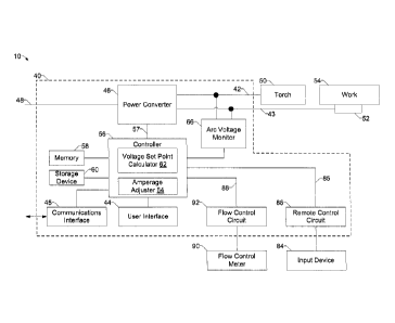
[0017] FIG. 1 is a block diagram illustrating an example welding system 10
including a
power source 40. The power source 40 converts input power to AC and/or DC
power suitable for
use in gouging operations such as air carbon arc gouging. In some examples,
the power source
40 also supports welding operations, such as TIG, stick welding, and/or
Submerged Arc Welding
(SAW). The power source 40 permits an operator to use the power source 40 for
gouging and/or
welding by selecting the appropriate operation via a user interface 44, and
attaching the
appropriate welding equipment, (e.g. a gouging torch and gas supply for air
carbon arc gouging,
a torch and gas supply for TIG welding, or an electrode holder for STICK
welding, etc.).
[0018] The power source 40 includes a power converter 46. The power
converter 46 receives
input power from a power input 48 and converts the power input 48 to either AC
and/or DC
welding power for output to a torch 50 connected to power outputs 42, 43. In
the example of
-6-
CA 02952217 2016-12-20
FIG. 1, the torch 50 is connected to the power output 42 and a work clamp 52
is connected to a
power output 43 to form an electrical circuit with a workpiece 54 when an
electrical arc is
started.
[0019] The power converter 46 is a phase-controlled power source, which may
use silicon
controlled rectifiers (SCRs) to convert power received at power input 48 to
usable welding
and/or gouging power. Additionally or alternatively, the power converter 46
may use DC
chopper circuity and/or any other power conversion topology.
[0020] The power source 40 includes a controller 56 that is operatively
coupled to the power
converter 46. The controller 56 may be implemented using one or more logic
circuits, such as
one or more "general-purpose" microprocessors, one or more special-purpose
microprocessors
and/or application-specific integrated circuits (ASIC), field programmable
gate arrays (FPGA)s,
digital signal processors (DSPs), and/or any other type of logic and/or
processing device. For
example, the controller 56 may include one or more digital signal processors
(DSPs).
Alternatively, the controller 56 could include discrete component control
circuitry to perform
these control functions. The controller 56 controls the output power from
power converter 46 by
generating control signals 57 to control switching components (e.g., the SCRs)
in power
converter 46.
[0021] The controller 56 receives user-selected operating parameters from
user interface 44,
such as an amperage (e.g., electrical current) selection. For example, the
user interface 44
includes selectors (not shown) operable by the user to select a welding
process (e.g., gouging,
TIG, STICK, etc.), an amperage control (PANEL/REMOTE), an output control
(ON/REMOTE),
a start mode (OFF/LIFT/HFSTART/HFCONT), a positive/negative balance control
for AC TIG
welding, a DIG control for STICK welding, an amperage level, a spot welding
operation, and/or
-7-
CA 02952217 2016-12-20
a sequence selection such as start current, final (crater) current, or both.
The controller 56 also
transmits to the user interface 44 information about the welding operation
that is valuable to the
welder, including arc voltage, arc amperage, and/or preferred selector
settings. The example user
interface 44 may include any type of interface device, such as a keyboard, a
pointing device
(e.g., a mouse, a trackpad), a microphone, a camera (e.g., gesture-based
input), a touchscreen,
and/or any other type of user input and/or output device.
100221 In some examples, the controller 56 may receive the amperage
parameter via a
communication interface 45 from another device instead of via the user
interface. For example,
the controller 56 may receive the amperage parameter via a wired and/or
wireless network
communication from a computing device (e.g., a computer, a server, a mobile
device, cloud
storage, etc.), a wired and/or wireless point-to-point connection (e.g.,
Bluetooth(R), near-field
communications, etc.), a control cable communication with another welding
device, a weld cable
communication from another welding device, a communication with a storage
device such as a
portable storage device (e.g., a FLASH drive or other USB-capable storage, a
secure digital (SD)
card, etc.), and/or via any other communications method.
100231 A memory device 58 and a storage device 60 are coupled to the
controller 56 for
storing data including the settings of the selectors on user interface 44 for
future retrieval after
power-down and/or between welding cycles. The memory device 58 may include a
volatile
memory, such as random access memory (RAM), and/or a nonvolatile memory, such
as read-
only memory (ROM). The storage device 60 may include magnetic media such as a
hard disk,
solid state storage, optical media, and/or any other short and/or long term
storage device. The
memory device 58 and/or the storage device 60 may store information (e.g.,
data) for any
purpose and/or transmit stored data upon request by the controller 56. For
example, the memory
-8-
CA 02952217 2016-12-20
device 58 and/or the storage device 60 may store processor executable
instructions (e.g.,
firmware or software) for the controller 56 to execute. In addition, one or
more control schemes
for various welding processes, along with associated settings and parameters,
may be stored in
the memory device 58 and/or the storage device 60, along with code configured
to provide a
specific output (e.g., initiate wire feed, enable gas flow, capture welding
current data, detect
short circuit parameters, determine amount of spatter) during operation.
100241 The memory device 58 may include a volatile memory, such as random
access
memory (RAM), and/or a nonvolatile memory, such as read-only memory (ROM). The
memory
device 58 may store a variety of information and may be used for various
purposes. For example,
the memory device 58 may store processor executable instructions (e.g.,
firmware or software)
for the controller 56 to execute. In addition, one or more control regimes for
various welding
processes, along with associated settings and parameters, may be stored in the
memory device 58
and/or the storage device 60, along with code configured to provide a specific
output (e.g.,
initiate wire feed, enable gas flow, capture welding current data, detect
short circuit parameters,
determine amount of spatter) during operation.
100251 When an operator is performing a gouging operation, the arc voltage
may vary
depending on, for example, the distance between the electrode tip and the
workpiece. In some
cases, with insufficient power being directed to the electrode, the electrode
can be caused to
"stub out," or stick to the workpiece. Additionally or alternatively, if
inconsistent distances occur
between the electrode and the workpiece due to, for example, physical
unsteadiness in
manipulation of the torch by the operator and/or an inconsistent travel speed
can cause the
resulting gouging arc to be inconsistent when using conventional power
supplies.
-9-
CA 02952217 2016-12-20
[0026] The example controller 56 includes a voltage set point calculator 62
and an amperage
adjuster 64. The voltage set point calculator 62 set a voltage set point based
on the amperage
parameter and a voltage correction factor. In some examples, the voltage set
point approximates
an expected operating voltage of a gouging operation using a selected amperage
parameter. The
amperage adjuster 64 adjusts an amperage of an arc (e.g., by sending the
control signal 57 to the
power converter 46) based on a detected voltage of the arc. To this end, the
power source 40
includes an arc voltage monitor 66 to measure the arc voltage at the power
outputs 42, 43. The
arc voltage monitor 66 measures the arc voltage and compares the measured arc
voltage to a
voltage threshold. Based on the comparison of the measured arc voltage to the
voltage threshold,
the arc voltage monitor 66 provides an amperage adjustment signal 57 to the
amperage adjuster
64.
[0027] The amperage adjustment signal 57 may identify one of multiple
voltage-amperage
relationships to be used by the amperage adjuster 64 to determine an
adjustment to the amperage
output by the power converter 46. In the example of FIG. 1, the amperage
adjuster 64 uses a first
voltage-amperage relationship (e.g., a voltage-dependent curve) when the arc
voltage is less than
the threshold used by the arc voltage monitor 66 and uses a second voltage-
amperage
relationship (e.g., a voltage-independent curve) when the arc voltage is
greater than the
threshold. Example voltage-amperage relationships are illustrated in Equations
1 and 2 below.
[0028] 1r = /set + 20 * (Vset ¨ V) (Equation 1)
[0029] 1 = 'set ¨ 20 * (Vt Vset) (Equation 2)
[0030] In Equations 1 and 2 above, / is the output amperage determined by
the amperage
adjuster 64, Let is the amperage parameter received via the user interface 44,
Vset is the voltage
set point identified by the voltage set point calculator 62, and V is arc
voltage measured by the
-10-
CA 02952217 2016-12-20
arc voltage monitor 66. Equation 1 is based on the amperage parameter, the
voltage set point,
and the measured voltage, while Equation 2 is based on the amperage parameter
and the voltage
set point. When the measured voltage V is higher than the threshold, the
amperage adjuster 64
uses Equation 1 to adjust the amperage. In contrast, when the measured voltage
V is less than the
threshold, the amperage adjuster 64 uses Equation 2 to adjust the amperage.
100311 In some examples, the amperage adjuster 64 uses Equation 1 to
determine the output
amperage only when the measured voltage is at least 18V and is less than 40V.
In some
examples, the amperage adjuster 64 uses Equation 1 to determine the output
amperage only
when the measured voltage is at least 24V and is less than 32V. However, the
amperage adjuster
64 may use any lower voltage limit (e.g., a lower voltage limit between 18V
and 24V) and/or any
upper voltage limit (e.g., an upper voltage limit between 32V and 40V) when
selecting Equation
1 to determine the output amperage.
100321 The controller 56 also receives remote control inputs 85 from an
input device 84
through a remote control circuit 86. The input device 84 is user-operable and
can be used to
control welding power output. The flow of shield gas and/or gouging gas may
also be controlled
by controller 56. In this embodiment, a control signal 88 is sent from
controller 56 via a path
through a flow control circuit 92 to a flow control meter 90. Flow control
meter 90 is coupled to
a gas supply (not shown) for regulating the flow of shield gas and/or gouging
gas from the gas
supply to a welding site (e.g., to the torch 50). The flow control meter 90
may be internal or
external to the power source 40 with a gas flow channel (not shown) extending
from the gas
supply, through power source 40, through flow control meter 90, then out to
the 50 for provision
to the site of the operation. The flow control circuit 92 could also be a
submerged arc flux
controller or a flux hopper controller.
-11-
CA 02952217 2016-12-20
[0033] FIG. 2 is a graph 200 illustrating amperage-voltage curves 202, 204,
206, 208 used by
a conventional welding system. The amperage curves 202-208 correspond to
amperage
selections by a user, such as 200A, 400A, 600A, and 800A. As illustrated in
the amperage curves
202-208, when a voltage decreases below a voltage level 210 (e.g.,
corresponding to a stuck
electrode), the conventional amperage-voltage curves 202-208 causes a
conventional power
source to increase the amperage as the voltage decreases below the voltage
level 210.
[0034] FIG. 3 is a graph 300 illustrating example amperage-voltage curves
302, 304, 306,
308 and an example voltage set point curve 310 used by the example power
source 40 of FIG. 1
to improve the performance of gouging operations. The example amperage-voltage
curves 302-
308 correspond to amperage selections of 200A, 400A, 600A, and 800A. When a
user selects an
amperage setting, the example voltage set point calculator 62 calculates a
voltage set point along
a voltage set point curve 310, such as a voltage at which the voltage set
point curve 310
intersects with the correspondence amperage-voltage curve 320-308. The example
voltage set
point curve 310 corresponds to Equation 3 below, where /õ, is the selected
amperage input to the
controller 56 (e.g., via the user interface 44, via the communication
interface 45) and Vset is the
selected voltage set point. In an example, the voltage set point calculator 62
sets a voltage set
point of 32V for a selection of 800A (e.g., the amperage-voltage curve 308. As
shown in FIG. 3
and Equation 3 below, the voltage set point curve 310 has a negative slope
(e.g., the weld
amperage has an inverse relationship with the weld voltage).
[0035] Vsetiset
= 40 ¨ ¨ (Equation 3)
Imo
[0036] When the arc starts, the arc voltage monitor 66 measures the
voltage. Based on the
amperage-voltage curve 308 for the selected amperage, the example amperage
adjuster 64
controls the power converter 46 to output an amperage corresponding to the
measured voltage. If
-12-
CA 02952217 2016-12-20
the measured voltage is below a threshold level 312 (e.g., a threshold higher
than the voltage set
point level 310, 40V in the example of FIG. 3), the example amperage adjuster
64 uses the
example Equation 1. In contrast, if the measured voltage is above a threshold
level 312, the
amperage adjuster 64 uses the example Equation 2.
[0037] While example amperage-voltage curves 302-308 are shown in FIG. 3
for the
purposes of illustration, more, fewer, and/or different amperage-voltage
curves may be used by
the amperage adjuster 64. Further, the example set point curve 310 and/or the
example threshold
may be the same or different than shown in FIG. 3 based on the particular
implementation.
[0038] FIG. 4 is a flowchart illustrating example machine readable
instructions 400 which
may executed to implement the power source 40 of FIG. 1 to control an amperage
output. The
instructions 400 may be executed to implement the controller 56, the voltage
set point calculator
62, the amperage adjuster 64, the arc voltage monitor 66, and/or the power
converter 46.
[0039] At block 402, the example voltage set point calculator 62 receives
an amperage
selection (e.g., an amperage corresponding to one of the curves 302-308. For
example, the
voltage set point calculator 62 may receive the amperage selection from the
user interface 44
and/or from the communications interface 45.
[0040] At block 404, the voltage set point calculator 62 calculates a
voltage set point based
on the amperage parameter and a voltage correction factor. For example, the
voltage set point
calculator 62 may determine a voltage set point based on the intersection
between an amperage-
voltage curve (e.g., the amperage-voltage curve 308) and a set point curve
(e.g., the set point
curve) 310 of FIG. 3.
[0041] At block 406, the voltage set point calculator 62 determines whether
there has been
an amperage parameter change. For example, the voltage set point calculator 62
may identify a
-13-
CA 02952217 2016-12-20
change in the amperage selection via the user interface 44 and/or via the
communications
interface 45. If there is change in the amperage parameter (block 406),
control returns to block
402.
[0042] If there has not been an amperage parameter change (block 406), at
block 408 the
controller 56 determines whether the arc is present. For example, the power
source 40 and/or the
arc voltage monitor 66 may detect the presence of an arc by measuring an
output current and/or
an output voltage at the power outputs 42, 43, and/or the controller 56 may
receive a signal from
a trigger of the torch 50. Any other method of determining whether the arc is
present may be
used. If the arc is not present (block 408), control returns to block 406.
[0043] When the arc is present (block 408), at block 410 the controller 56
controls the power
converter 46 to output electrical energy based on the amperage parameter and
the voltage set
point. For example, the amperage adjuster 64 may control the power converter
46 to output a
voltage and an amperage corresponding to the selected amperage-voltage curve
308. The output
from the power converter 46 may be used to establish and maintain an
electrical arc and/or for
non-arc welding processes such as hot-wire welding.
[0044] At block 412 the arc voltage monitor 66 measures the output voltage.
At block 414,
the arc voltage monitor 66 determines whether the measured voltage is greater
than a threshold
voltage. The example threshold voltage used by the arc voltage monitor 66 may
be the voltage
level 312 of FIG. 3.
[0045] If the measured voltage is not greater than the threshold voltage
(block 414), at block
416 the amperage adjuster 64 adjusts the output amperage via the power
converter 46 based on
the amperage parameter, the voltage set point, and the measured voltage using
a first amperage-
voltage relationship. The example first amperage-voltage relationship may be
Equation 1 above
-14-
CA 02952217 2016-12-20
and/or the portion of the amperage-voltage curve 308 below the threshold level
312. However,
another amperage-voltage relationship may be used based on the application
and/or empirical
observations.
[0046] If the measured voltage is greater than the threshold voltage (block
414), at block 418
the amperage adjuster 64 sets the output amperage via the power converter 46
based on the
amperage parameter and the voltage set point using a second amperage-voltage
relationship. The
example first amperage-voltage relationship may be Equation 2 above and/or the
portion of the
amperage-voltage curve 308 above the threshold level 312. However, another
amperage-voltage
relationship may be used based on the application and/or empirical
observations.
[0047] After adjusting the output amperage (block 416 or block 418),
control returns to block
406 to determine whether there has been a change in the amperage parameter.
[0048] As illustrated in the instructions 400 of FIG. 4, changing of the
amperage parameter
may occur while the electrical arc is present and/or is not present. For
example, blocks 402-46
may be performed while a gouging operation is occurring.
[0049] The present methods and systems may be realized in hardware,
software, and/or a
combination of hardware and software. The present methods and/or systems may
be realized in a
centralized fashion in at least one computing system, or in a distributed
fashion where different
elements are spread across several interconnected computing systems. Any kind
of computing
system or other apparatus adapted for carrying out the methods described
herein is suited. A
typical combination of hardware and software may include a general-purpose
computing system
with a program or other code that, when being loaded and executed, controls
the computing
system such that it carries out the methods described herein. Another typical
implementation
may comprise an application specific integrated circuit or chip. Some
implementations may
-15-
CA 02952217 2016-12-20
comprise a non-transitory machine-readable (e.g., computer readable) medium
(e.g., FLASH
drive, optical disk, magnetic storage disk, or the like) having stored thereon
one or more lines of
code executable by a machine, thereby causing the machine to perform processes
as described
herein. As used herein, the term "non-transitory machine-readable medium" is
defined to include
all types of machine readable storage media and to exclude propagating
signals.
[0050] As utilized herein the terms "circuits" and "circuitry" refer to
physical electronic
components (i.e. hardware) and any software and/or firmware ("code") which may
configure the
hardware, be executed by the hardware, and or otherwise be associated with the
hardware. As
used herein, for example, a particular processor and memory may comprise a
first "circuit" when
executing a first one or more lines of code and may comprise a second
"circuit" when executing
a second one or more lines of code. As utilized herein, "and/or" means any one
or more of the
items in the list joined by "and/or". As an example, "x and/or y" means any
element of the three-
element set {(x), (y), (x, y)} . In other words, "x and/or y" means "one or
both of x and y". As
another example, "x, y, and/or z" means any element of the seven-element set
{(x), (y), (z), (x,
y), (x, z), (y, z), (x, y, z)} . In other words, "x, y and/or z" means "one or
more of x, y and z". As
utilized herein, the term "exemplary" means serving as a non-limiting example,
instance, or
illustration. As utilized herein, the terms "e.g.," and "for example" set off
lists of one or more
non-limiting examples, instances, or illustrations. As utilized herein,
circuitry is "operable" to
perform a function whenever the circuitry comprises the necessary hardware and
code (if any is
necessary) to perform the function, regardless of whether performance of the
function is disabled
or not enabled (e.g., by a user-configurable setting, factory trim, etc.).
[0051] The present methods and/or systems may be realized in hardware,
software, or a
combination of hardware and software. The present methods and/or systems may
be realized in a
-16-
CA 02952217 2016-12-20
centralized fashion in at least one computing system, or in a distributed
fashion where different
elements are spread across several interconnected computing systems. Any kind
of computing
system or other apparatus adapted for carrying out the methods described
herein is suited. A
typical combination of hardware and software may be a general-purpose
computing system with
a program or other code that, when being loaded and executed, controls the
computing system
such that it carries out the methods described herein. Another typical
implementation may
comprise an application specific integrated circuit or chip. Some
implementations may comprise
a non-transitory machine-readable (e.g., computer readable) medium (e.g.,
FLASH drive, optical
disk, magnetic storage disk, or the like) having stored thereon one or more
lines of code
executable by a machine, thereby causing the machine to perform processes as
described herein.
100521
While the present method and/or system has been described with reference to
certain
implementations, it will be understood by those skilled in the art that
various changes may be
made and equivalents may be substituted without departing from the scope of
the present method
and/or system. In addition, many modifications may be made to adapt a
particular situation or
material to the teachings of the present disclosure without departing from its
scope. For example,
block and/or components of disclosed examples may be combined, divided, re-
arranged, and/or
otherwise modified. Therefore, the present method and/or system are not
limited to the particular
implementations disclosed. Instead, the present method and/or system will
include all
implementations falling within the scope of the appended claims, both
literally and under the
doctrine of equivalents.
-17-