Language selection

Search

Patent 2952280 Summary

Third-party information liability

Some of the information on this Web page has been provided by external sources. The Government of Canada is not responsible for the accuracy, reliability or currency of the information supplied by external sources. Users wishing to rely upon this information should consult directly with the source of the information. Content provided by external sources is not subject to official languages, privacy and accessibility requirements.

Claims and Abstract availability

Any discrepancies in the text and image of the Claims and Abstract are due to differing posting times. Text of the Claims and Abstract are posted:

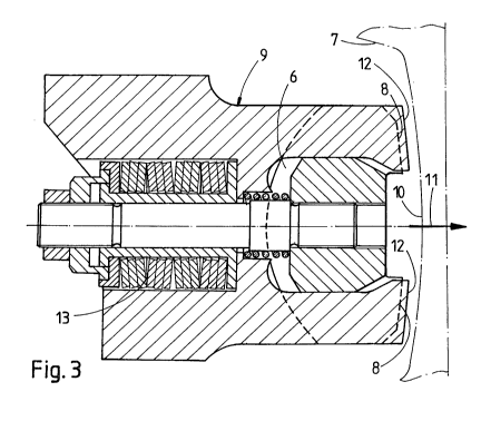
  • At the time the application is open to public inspection;
  • At the time of issue of the patent (grant).
(12) Patent Application: (11) CA 2952280
(54) English Title: WELDING UNIT
(54) French Title: UNITE DE SOUDAGE
Status: Dead
Bibliographic Data
(51) International Patent Classification (IPC):
  • E01B 29/46 (2006.01)
(72) Inventors :
  • STEINER, RONALD (Austria)
(73) Owners :
  • PLASSER & THEURER EXPORT VON BAHNBAUMASCHINEN GESELLSCHAFT M.B.H. (Austria)
(71) Applicants :
  • PLASSER & THEURER EXPORT VON BAHNBAUMASCHINEN GESELLSCHAFT M.B.H. (Austria)
(74) Agent: RICHES, MCKENZIE & HERBERT LLP
(74) Associate agent:
(45) Issued:
(86) PCT Filing Date: 2015-07-03
(87) Open to Public Inspection: 2016-02-04
Availability of licence: N/A
(25) Language of filing: English

Patent Cooperation Treaty (PCT): Yes
(86) PCT Filing Number: PCT/EP2015/001365
(87) International Publication Number: WO2016/015816
(85) National Entry: 2016-12-14

(30) Application Priority Data:
Application No. Country/Territory Date
A 592/2014 Austria 2014-07-28

Abstracts

English Abstract

The invention relates to a welding unit for connecting two rails (7) of a track by means of flash welding, comprising clamping jaws (6) provided with contact surfaces (8) designed to rest against a rail web (10), which welding unit is provided with a current jaw (9) having a contact surface (12) for transmitting current, intended to rest against the rail web (10). The current jaw (9) can be displaced relative to the clamping jaw (6) in a pressing direction so as to rest against the rail (7). In an inoperative position at a distance from the rail web (10), the current jaw (9), due to the pressure of a pressure spring (13), is in an end position that is frontal with regard to the pressing direction (11), in which end position the contact surface (12) of the current jaw (9) projects beyond the contact surface (8) of the clamping jaw (6).


French Abstract

L'invention concerne une unité de soudage, destinée à relier deux rails (7) d'une voie par soudage par étincelage, qui comprend des mâchoires de serrage (6) possédant des surfaces de contact (8) en appui sur une âme de rail (10) ; l'unité de soudage comporte pour le transfert de courant une mâchoire de courant (9) pourvue d'une surface de contact (12) en appui contre l'âme de rail (10). La mâchoire de courant (9) peut coulisser par rapport à la mâchoire de serrage (6) dans une direction de pressage (11) pour venir en appui contre le rail (7). Dans une position de repos à distance de l'âme de rail (10), la mâchoire de courant (9) se trouve en raison de la pression exercée par un ressort de pression (13) dans une position d'extrémité avant, par référence à la direction de pressage (11), dans laquelle la surface de contact (12) de la mâchoire de courant (9) dépasse de la surface de contact (8) de la mâchoire de serrage (6).

Claims

Note: Claims are shown in the official language in which they were submitted.


4

Claims
1. A welding unit (1) for connecting two rails (7) of a track by flash-butt
welding, the welding unit having clamping jaws (6) comprising contact surfaces

(8) intended for application to a rail web (10), characterized by the
following
features:
a) a power jaw (9) having a contact surface (12) for application to the
rail
web (10) is provided for current transmission,
b) the power jaw (9) is displaceable relative to the clamping jaw (6) in a
pressing direction (11) leading to contact with the rail (7),
c) in an inoperative position spaced from the rail web (10), the power jaw
(9)
¨ due to the pressure of a pressure spring (13) ¨ is situated in a forward end

position, with regard to the pressing direction (11), in which the contact
surface
(12) of the power jaw (9) projects beyond the contact surface (8) of the
clamping
jaw (6).
2. A welding unit according to claim 1, characterized in that the power jaw
(9) is fastened directly to the clamping jaw (6) and displaceable relative to
the
same in the pressing direction (11).

Description

Note: Descriptions are shown in the official language in which they were submitted.


CA 02952280 2016-12-14
r 1
Welding Unit
[01] The invention relates to a welding unit for connecting two rails of a
track
by flash-butt welding, the welding unit having clamping jaws comprising
contact surfaces intended for application to a rail web.
[02] A welding unit of this type is known from WO 2010/063362 Al. The
clamping jaws, each having two contact surfaces spaced from one
another, serve on the one hand for producing a maximal force lock
between the rail and the welding unit, and on the other hand also for
current transmission.
[03] It is the object of the present invention to provide a welding unit of
the
kind mentioned at the beginning with which an improved current
transmission is possible.
[04] According to the invention, this object is achieved with a welding
unit of
the specified type by way of the features cited in the characterizing
clause of the main claim.
[05] Due to this combination of features, the advantage is achieved of
having
a pressing force which is constant as well as optimal for the
transmission of current. Additionally, it is possible without problems to
grind away any traces of wear occurring on the contact surfaces of the
power jaws, without thereby detracting from the above-mentioned
advantages.

CA 02952280 2016-12-14
= 2
[06] Additional advantages of the invention become apparent from the
dependent claim and the drawing description.
[07] The invention will be described in more detail below with reference to
an
embodiment represented in the drawing in which Fig. 1 shows a view of
a welding unit, Fig. 2 shows a top view of a clamping- and power jaw,
and Fig. 3 shows a cross-section of the power jaw.
[08] A welding unit 1, represented in Fig. 1, for connecting two rails 7 of
a
track by means of flash-butt welding is composed of two unit
components 4 which are displaceable with respect to one another along
assembly guides 3 with the aid of displacement cylinders 2. Each of said
unit parts 4 is connected to two clamping drives 5 by means of which
clamping jaws 6 (not visible here, see Figs. 2, 3) can be pressed onto
the rails 7 to be welded to one another.
[09] The clamping jaw 6 shown in Figs. 2 and 3 has contact surfaces 8
intended for application to a rail web 10. One end of the clamping jaw 6
is connected to a power jaw 9 which is made of copper and provided for
the transmission of current. Said power jaw 9 is displaceable relative to
the clamping jaw 6 ¨ in a pressing direction 11 toward the rail 7 ¨ and
has contact surfaces 12 intended for application to the rail web 10.
[10] The power jaw 9 which is pre-stressed by the pressure of a spring 13,
preferably a disc spring, is situated in a forward end position in the
pressing direction 11, in which the contact surface 12 of the power jaw 9

CA 02952280 2016-12-14
3
¨ when in an inoperative position spaced from the rail web 10 (see Fig.
3) ¨ projects beyond the contact surface 8 of the clamping jaw 6. Thus,
a constant contact pressure of the power jaw 9 against the rail web 10 is
ensured as soon as the clamping jaw 6 is pressed to the rail 7. In an
advantageous manner, it is furthermore possible to regrind the contact
surfaces 12 of the power jaw 9 several times in order to thereby
eliminate slight damages of the surface to maintain the smallest possible
contact transmission resistance.
[11] As can be seen in Fig. 3, the power jaw 9 is fastened directly to the
clamping jaw 6 and pre-stressed in the pressing direction 11 by the
pressure of the spring 13. As soon as the clamping jaw 6 is pressed
against the rail web 10 for initiating a welding process, there is an
automatic backwards movement of the power jaw 9 opposite to the
pressing direction 11, until the two contact surfaces 8 and 12 are
positioned in a common plane.
Representative Drawing
A single figure which represents the drawing illustrating the invention.
Administrative Status

For a clearer understanding of the status of the application/patent presented on this page, the site Disclaimer , as well as the definitions for Patent , Administrative Status , Maintenance Fee  and Payment History  should be consulted.

Administrative Status

Title Date
Forecasted Issue Date Unavailable
(86) PCT Filing Date 2015-07-03
(87) PCT Publication Date 2016-02-04
(85) National Entry 2016-12-14
Dead Application 2021-11-23

Abandonment History

Abandonment Date Reason Reinstatement Date
2020-11-23 FAILURE TO REQUEST EXAMINATION
2021-03-01 FAILURE TO PAY APPLICATION MAINTENANCE FEE

Payment History

Fee Type Anniversary Year Due Date Amount Paid Paid Date
Application Fee $400.00 2016-12-14
Maintenance Fee - Application - New Act 2 2017-07-04 $100.00 2017-06-09
Maintenance Fee - Application - New Act 3 2018-07-03 $100.00 2018-06-06
Maintenance Fee - Application - New Act 4 2019-07-03 $100.00 2019-06-14
Owners on Record

Note: Records showing the ownership history in alphabetical order.

Current Owners on Record
PLASSER & THEURER EXPORT VON BAHNBAUMASCHINEN GESELLSCHAFT M.B.H.
Past Owners on Record
None
Past Owners that do not appear in the "Owners on Record" listing will appear in other documentation within the application.
Documents

To view selected files, please enter reCAPTCHA code :


To view images, click a link in the Document Description column. To download the documents, select one or more checkboxes in the first column and then click the "Download Selected in PDF format (Zip Archive)" or the "Download Selected as Single PDF" button.

List of published and non-published patent-specific documents on the CPD .

If you have any difficulty accessing content, you can call the Client Service Centre at 1-866-997-1936 or send them an e-mail at CIPO Client Service Centre.


Document
Description 
Date
(yyyy-mm-dd) 
Number of pages   Size of Image (KB) 
Abstract 2016-12-14 2 92
Claims 2016-12-14 1 25
Drawings 2016-12-14 1 42
Description 2016-12-14 3 88
Representative Drawing 2016-12-14 1 23
Cover Page 2017-01-30 1 52
Maintenance Fee Payment 2017-06-09 1 54
Maintenance Fee Payment 2018-06-06 1 52
Maintenance Fee Payment 2019-06-14 1 50
Modification to the Applicant-Inventor 2016-12-28 3 103
International Search Report 2016-12-14 4 140
Amendment - Abstract 2016-12-14 1 19
National Entry Request 2016-12-14 4 122
Acknowledgement of National Entry Correction 2017-02-01 3 174