Note: Descriptions are shown in the official language in which they were submitted.
CA 02952302 2016-12-14
WO 2016/014421
PCT/US2015/041158
WEIGHING SCALE DIAGNOSTICS METHOD
TECHNICAL FIELD
[0001]
Embodiments of the invention generally relate to weighing scale
diagnostic methods employing a comparison of like component operating
parameters.
BACKGROUND
[0002] Weighing
scales exist in many forms, from small laboratory scales to
large vehicle weighing scales. Of particular interest herein are weighing
scales
having multiple force measuring devices, which force measuring devices may
be modular in nature.
[0003] A scale
having multiple force measuring devices will also typically
include a frame, a load receiving surface that interfaces with the force
measuring devices, and a controller and/or monitor that receives signals from
the force measuring devices and typically provides a readout of the weight of
an object residing on the scale.
[0004] A
vehicle weighing scale is a common example of a multiple force
measuring device weighing scale. A typical vehicle weighing scale includes at
least one scale platform (or deck) for receiving a vehicle to be weighed. Such
a
scale platform is often comprised of a metal framework with a steel plate
deck,
or the scale platform may be comprised of concrete (typically enclosed within
a
steel frame). The scale platform is normally supported from beneath by a
number of force measuring devices, such as load cells. Vehicle weighing
scales are also typically constructed with two rows of load cells aligned in
the
1
CA 02952302 2016-12-14
WO 2016/014421
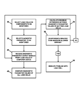
PCT/US2015/041158
direction of vehicle travel across the scale platform. When a vehicle is
placed
on the scale platform, each load cell produces an output signal that reflects
the
portion of the vehicle weight borne by that load cell. The signals from the
load
cells are added to produce an indication of the total weight of the vehicle
residing on the scale platform of the weighing scale.
[0005] Vehicle weighing scales, and their associated scale platforms, can
be
of various size. For example, such vehicle weighing scales are commonly of a
size that is sufficient to accommodate a multi-axle vehicle, such as a semi-
truck
trailer. Vehicle scales of such size may be assembled using multiple scale
platform segments (modules) that are connected end-to-end to provide a full-
length scale platform.
[0006] As should be obvious, the ability to monitor a weighing scale for
proper function is desirable. In order to do so, a monitoring methodology must
be developed and particular scale behavior, or the behavior (e.g., operating
characteristics) of one or more scale components must be evaluated.
[0007] It is known to evaluate weighing scale function by monitoring the
operational characteristics of the scale's force measuring devices. More
particularly, one or more selected force measuring device operational
characteristics may be monitored and compared to a corresponding expected
operational characteristic. Associated threshold values may then be set around
the expected operational characteristic, with a reading below or above said
threshold values being indicative of improper operation or some other problem.
[0008] A negative issue associated with such a known evaluation
methodology is that of setting individual component operating characteristic
2
CA 02952302 2016-12-14
WO 2016/014421
PCT/US2015/041158
threshold values. The threshold values are generally set to trigger an alarm
or
to provide some other notice or indication if monitored force measuring device
operational characteristics exceed the preset threshold values. However, in
practice it is often difficult to determine the correct individual component
operating characteristic threshold value to apply. For example, an individual
component operating characteristic threshold value that is set too low may
trigger false alarms, while a threshold value that is set too high may not
trigger
an alarm when a problem actually exists. This problem may be exacerbated
when the normal value range for a given operating characteristic is very
small.
Likewise, it may also be particularly difficult for an end user without
appropriate
technical knowledge and/or training to select appropriate individual component
operating characteristic threshold values, which may be required in some
cases.
[0009] From the
foregoing discussion, it should be apparent that there is a
need for improved weighing scale diagnostic methods. Exemplary method
embodiments described herein satisfy this need.
SUMMARY
[0010] Exemplary weighing scale diagnostic method embodiments
described herein generally include monitoring and comparing one or more
operating parameters of like scale components, which are, for purposes of the
invention, scale components that under normal conditions will have at least
one
common monitorable parameter that has approximately the same value for
each component. Exemplary weighing scale diagnostic method embodiments
3
CA 02952302 2016-12-14
WO 2016/014421
PCT/US2015/041158
described herein are, therefore, adapted particularly for use with weighing
scales having multiple like components. Like weighing scale components may
include, but are not limited to, a plurality of the same or similar force
measuring
devices, which may be in the form of force measuring modules. An operating
parameter of such a like component may be any component parameter having
a monitorable output that may be used as an indicator of component or scale
health. With respect to force measuring devices, such operating parameters
may include, but are not necessarily limited to, zero balance change (i.e.,
weight output change over time with only the dead load applied), temperature,
digital signal voltage and supply voltage.
[0011] Unlike
the aforementioned known methods of evaluating weighing
scale function, which require the establishment and setting of individual
component operating characteristic threshold values, exemplary method
embodiments according to the invention may be practiced by comparing the
same parameter of a plurality of like components present in a given weighing
scale. For
example, various operating parameters of the force measuring
devices present in a multiple force measuring device weighing scale may be
compared and evaluated.
[0012] Since
the simultaneous failure of several weighing scale components
is an unlikely occurrence, it is possible to evaluate component or scale
health
by selecting as a diagnostic parameter a given operating parameter that is
common to all of a plurality of like components that are present in a given
weighing scale, and then comparing the values of the selected diagnostic
parameters of all the like components. A component with a monitored
4
CA 02952302 2016-12-14
WO 2016/014421
PCT/US2015/041158
diagnostic parameter having a value that is an outlier in comparison to (i.e.,
that
deviates too far from) the diagnostic parameter values of the other like
components of the scale may be indicative of a problem with the associated
component. Consequently, scale health may be evaluated by setting a limit on
the relative difference (spread) between the diagnostic parameter values of
the
like components. Alternatively, a limit may be set on the deviation of a given
diagnostic parameter value from a calculated measure of central tendency of
the diagnostic parameters of the other like components, wherein the central
tendency is defined as the central or typical value associated with a
probability
distribution and wherein common measures of central tendency include but are
not limited to the arithmetic median, mean and mode. Still alternatively, a
standard statistical test may be applied to detect an outlying diagnostic
parameter value.
[0013] In any case, threshold values do not need to be set on a
diagnostic
parameter value itself. That is, the determination of whether or not a given
diagnostic parameter value indicates a problem does not depend on a specific
value itself, but rather on how the value compares to the diagnostic parameter
values of the other like components. This allows the diagnostic parameter
comparison to adapt to changing conditions, which is useful because in one
case specific diagnostic parameter values may be indicative of a problem while
in another case the same specific diagnostic parameter values may not be
indicative of a problem.
[0014] One exemplary weighing scale diagnostic method includes selecting
a plurality of like weighing scale components to be monitored; selecting an
CA 02952302 2016-12-14
WO 2016/014421
PCT/US2015/041158
operating parameter common to the selected weighing scale components as a
diagnostic parameter; receiving at a computer device output signals
representative of the selected diagnostic parameter from each of the selected
scale components; comparing the output signal value received from each
selected weighing scale component to the output signal values received from
all of the other selected weighing scale components; calculating the maximum
difference between the output signal values of any two selected weighing scale
components; comparing the maximum difference between the output signal
values of any two selected weighing scale components with a maximum
allowed difference; and, if the calculated difference is determined to exceed
the
maximum allowed difference, indicating a weighing scale component problem.
[0015] Another exemplary weighing scale diagnostic method includes
selecting a plurality of like weighing scale components to be monitored;
selecting an operating parameter common to the selected weighing scale
components as a diagnostic parameter; receiving at a computer device output
signals representative of the selected diagnostic parameter from each of the
selected scale components; calculating a measure of central tendency of the
received diagnostic parameter output signal values received from the selected
weighing scale components; comparing the diagnostic parameter output signal
value of each weighing scale component to the calculated measure of central
tendency value; calculating a deviation of the diagnostic parameter output
signal value of each weighing scale component from the calculated measure of
central tendency value; and, if the calculated deviation associated with a
given
6
CA 02952302 2016-12-14
WO 2016/014421
PCT/US2015/041158
weighing scale component exceeds a maximum allowed deviation, indicating a
problem with that weighing scale component.
[0016] Yet
another exemplary weighing scale diagnostic method includes
selecting a plurality of like weighing scale components to be monitored;
selecting an operating parameter common to the selected weighing scale
components as a diagnostic parameter; receiving at a computer device output
signals representative of the selected diagnostic parameter from each of the
selected scale components; applying a standard statistical test for outliers;
and,
if the diagnostic parameter value associated with a given weighing scale
component is statistically determined to be an outlier, indicating a problem
with
that weighing scale component.
[0017] In such
exemplary implementations, the weighing scale may be a
vehicle scale. In such
exemplary implementations, the weighing scale
components to be monitored are the force measuring devices (e.g., modules)
of the weighing scale, and the force measuring devices may be load cells. In
such exemplary implementations, the selected diagnostic parameter may be for
example the load cell temperature, digital signal voltage, supply voltage, or
zero balance change.
[0018]
According to one exemplary implementation of a diagnostic method
of the invention, the selected diagnostic parameter is the temperature of the
individual force measuring devices of a multiple force measuring device
weighing scale. In this exemplary implementation, the temperature of all the
like force measuring devices in the system is monitored. A temperature output
is typically available from force measuring devices such as load cells for use
by
7
CA 02952302 2016-12-14
WO 2016/014421
PCT/US2015/041158
a load cell metrology compensation algorithm. The temperature of the force
measuring devices is primarily determined by the environmental temperature
and, therefore, should be approximately the same for all of the like force
measuring devices of the scale. While some small difference in individual
force
measuring device temperature readings may be expected due to the physical
distance between the force measuring devices, a temperature difference
between any two like force measuring devices that exceeds some difference
limit, a temperature of a given force measuring device that deviates more than
some maximum allowed amount from a calculated measure of central tendency
of the temperature value of the other like force measuring devices, or a
temperature of a given force measuring device that is determined by
statistical
analysis to be an outlier from the temperature of other like force measuring
devices may indicate a problem (e.g., a failing temperature sensor) and can be
used to trigger an alert, such as an alarm.
[0019]
According to another exemplary implementation of a diagnostic
method of the invention, the selected diagnostic parameter is the supply
voltage of the individual force measuring devices of a multiple force
measuring
device weighing scale. In this exemplary implementation, an operating supply
voltage is provided by a controller (e.g., a terminal) to all of the like
force
measuring devices of the scale. The supply voltage at each force measuring
device is monitored. The supply voltage should be approximately the same for
all of the force measuring devices in the system. While some small difference
in the individual supply voltage values can be expected due to varying cable
lengths, a supply voltage difference between any two like force measuring
8
CA 02952302 2016-12-14
WO 2016/014421
PCT/US2015/041158
devices that exceeds some difference limit, a supply voltage of a given force
measuring device that deviates more than some maximum allowed amount
from a calculated measure of central tendency of the supply voltage of the
other like force measuring devices, or a supply voltage of a given force
measuring device that is determined by statistical analysis to be an outlier
based on the supply voltages of the other like force measuring devices may
indicate a problem (e.g., a damaged cable) and can be used to trigger an
alert,
such as an alarm.
[0020] Yet another exemplary diagnostic method embodiment of the
invention includes selecting a plurality of like weighing scale components to
be
monitored; selecting an operating parameter common to the selected weighing
scale components as a diagnostic parameter; receiving at a computer device
output signals representative of the selected diagnostic parameter from each
of
the selected scale components; calculating a deviation of the output signal
value received from each selected scale component with a stored value
established during a known good state of operation (e.g., at calibration);
calculating a total deviation by summing the calculated output signal value
deviations of each selected scale component; comparing the calculated total
deviation against a first predetermined threshold value; if the total
deviation is
determined to exceed the first predetermined threshold value, calculating the
percentage of total deviation that is attributable to each selected scale
component and then comparing the percentage of total deviation that is
attributable to each selected scale component to a second predetermined
threshold value; and if the total deviation attributable to a given selected
scale
9
CA 02952302 2016-12-14
WO 2016/014421
PCT/US2015/041158
component is determined to exceed the second predetermined threshold value,
indicating a problem with that selected scale component.
[0021] A weighing scale evaluated using a method wherein the percentage
of total deviation that is attributable to each selected scale component is
compared to a second predetermined threshold value may be also be a vehicle
scale, the weighing scale components to be monitored may again be the force
measuring devices of the weighing scale, and the force measuring devices may
be load cells (e.g., load cell modules). In such an exemplary implementation,
the selected diagnostic parameter may be the zero drift of the force measuring
devices (e.g., load cells), the calculated deviation of the output signal
value
received from each force measuring device may be the zero drift of each force
measuring device, and the calculated total deviation may be the total zero
drift
of the scale. In such an exemplary implementation, the first predetermined
threshold value may be some percentage of scale capacity and the second
predetermined threshold value may be some percentage of total zero drift.
[0022] According to one such exemplary implementation of this diagnostic
method, the selected diagnostic parameter is the zero balance change of the
individual force measuring devices (e.g., load cell modules) of a multiple
force
measuring device weighing scale. The zero balance change is the difference
between the zero balance value at the current time compared with its value at
the time of calibration. In this exemplary implementation, the zero balance
change of all the individual force measuring devices is monitored. The zero
balance change should be approximately the same for all of the force
measuring devices of the scale. While some small difference in the zero
CA 02952302 2016-12-14
WO 2016/014421
PCT/US2015/041158
balance change can be expected due to the accumulation of debris on the
scale platform, a zero balance change of a given force measuring device that
represents a significant percentage of the total zero balance change of all
the
force measuring devices may indicate a problem (e.g., a failing force
measuring
device) and can be used to trigger an alert, such as an alarm.
[0023]
Diagnostic method embodiments according to the invention are
implemented on a computer device, such as a processor executing appropriate
instructions. The processor may be associated with a software program for this
purpose. In at least some embodiments, the computer device may be a scale
terminal, which is a device that is in wired or wireless communication with
the
scale and may function to control the scale, display weight readings, display
diagnostic information, etc. In other
embodiments, diagnostic methods
according to the invention may be carried out on a computer device that is
separate from the scale terminal, and which may or may not be in
communication therewith.
[0024] Other
aspects and features of the invention will become apparent to
those skilled in the art upon review of the following detailed description of
exemplary embodiments along with the accompanying drawing figures.
BRIEF DESCRIPTION OF THE DRAWINGS
[0025] In the
following descriptions of the drawings and exemplary
embodiments, like reference numerals across the several views refer to
identical or equivalent features, and:
11
CA 02952302 2016-12-14
WO 2016/014421
PCT/US2015/041158
[0026] FIG. 1 schematically represents a typical vehicle weighing scale
having multiple force measuring devices in the form of load cells;
[0027] FIG. 2 is a side view of the exemplary weighing scale of FIG. 1;
[0028] FIG. 3 is a flowchart illustrating the implementation of one
exemplary
diagnostic method according to the invention;
[0029] FIG. 4 is a flowchart illustrating the implementation of another
exemplary diagnostic method according to the invention;
[0030] FIG. 5 is a flowchart illustrating the implementation of yet
another
exemplary diagnostic method according to the invention, and
[0031] FIG. 6 is a flowchart illustrating the implementation of still
another
exemplary diagnostic method according to the invention.
DETAILED DESCRIPTION OF THE EXEMPLARY EMBODIMENT(S)
[0032] As explained above, weighing scales exist in many forms, sizes and
capacities. While method embodiments of the invention are not limited in
application to weighing scales of any particular form, size or capacity, said
methods are adapted for use with weighing scales having a plurality of like
components. The like components may be force measuring devices. The
force measuring devices may be load cells or other devices usable to provide
weight indicative readings in one form or another.
[0033] One common exemplary embodiment of a multiple force
measuring device weighing scale is a multiple-load cell vehicle scale. One
such exemplary vehicle scale 5 is depicted in FIGS. 1-2 for purposes of
further
illustrating method embodiments of the invention. As shown, this exemplary
12
CA 02952302 2016-12-14
WO 2016/014421
PCT/US2015/041158
scale 5 includes a load receiving platform 10 supported by ten subjacent
digital
load cells 15 that are arranged in rows of two along the length of the load
receiving platform. The load cells 15 reside between an underside of the load
receiving platform 10 and the ground 20 or another support surface. In this
particular example, the load cells 15 are of rocker pin design, such that the
load
cells may tilt in response to the entry or exit of a vehicle and subsequently
return to substantially the same upright position. The reliability of the load
cells
15 is such that the simultaneous failure of several load cells is an unlikely
occurrence.
[0034] At least
the load cells 15 of the scale 5 are also in wired or
wireless communication (as indicated by the bi-directional arrows) with a
computer device 25 that is operative to control the scale, to display weight
readings when the scale is loaded, and possibly to display diagnostic
information related to the scale and its components. In this
particular
exemplary embodiment, the computer device is a scale terminal, which
includes a processor, memory, and appropriate programming.
[0035] When an object to be weighed (a vehicle, in this case) is located
on
the load receiving platform 10, the weight of the vehicle exerts a force on
the
load cells 15, each of which generates a digital output signal indicative of
the
weight supported by that load cell. Typically, the load cell output is
corrected,
as would be well known to one of skill in the art. The digital output signals
can
be summed to obtain the weight of the vehicle on the load receiving platform
10. The correction and summing functions may be performed at the terminal
25, or elsewhere.
13
CA 02952302 2016-12-14
WO 2016/014421
PCT/US2015/041158
[0036] One skilled in the art would understand that a variety of such
scales
exist, and this particular embodiment is presented only for purposes of
illustration. Furthermore, method embodiments according to the invention are
applicable to other scale and force measurement device designs.
[0037] Using still the vehicle scale 5 as an example, scale functionality
may
be evaluated in one embodiment by selecting as a diagnostic parameter(s) one
or more operating parameters that are common to each of the load cells 15.
The selected diagnostic parameter(s) have approximately the same value for
each load cell during normal operation. This diagnostic parameter(s) is then
monitored for each load cell 15 and the detected value associated with the
diagnostic parameter(s) of each load cell 15 is compared with the detected
values associated with the same diagnostic parameters of the other load cells
15.
[0038] As described above, exemplary embodiments of the invention may
be implemented by setting a limit on the allowable relative difference between
the monitored diagnostic parameters of the selected weighing scale
components, by comparing the diagnostic parameter output signal value of
each selected weighing scale component to a calculated measure of central
tendency (e.g., median) of the diagnostic parameter output signal value of the
selected weighing scale components, and/or by performing a standard
statistical test for outliers (e.g., Chauvenet's Criterion, Grubbs' Test for
Outliers,
Peirce's Criterion, Dixon's Q Test, etc.) on the monitored diagnostic
parameters
of the selected weighing scale components. An illustration of exemplary
14
CA 02952302 2016-12-14
WO 2016/014421
PCT/US2015/041158
embodiments of said methods may be easily made using the exemplary vehicle
weighing scale depicted in FIGS. 1-2.
[0039] In one exemplary diagnostic method, which is represented in the
flow
chart of FIG. 3, the load cells 15 of the scale 5 are selected as the
component
to be monitored 30 and a diagnostic parameter (e.g., temperature, digital
signal
voltage, supply voltage, or zero balance change) of the individual load cells
15
of the vehicle weighing scale 5 is selected to be monitored 35. Appropriate
diagnostic parameter signals from the load cells 15 are received 40 by the
computer device (e.g., terminal) 25.
[0040] Once the diagnostic parameter signals are received 40 from all of
the
load cells 15, the diagnostic parameter value of each load cell 15 is compared
to the diagnostic parameter values of the other load cells 45, and a
calculated
difference between the diagnostic parameter values of any two load cells is
calculated 50. The calculated differences between the diagnostic parameter
values of all the load cells are then evaluated 55. If the difference in
diagnostic
parameter values between a given load cell and the other load cells 15 does
not exceed a maximum allowed spread, then no problem is indicated and the
process returns to the point of receiving a new set of diagnostic parameter
signals 40 from all of the load cells 15. If the difference in diagnostic
parameter
values between a given load cell and the other load cells 15 exceeds a
maximum allowed spread, then a problem with that load cell is indicated 60.
[0041] In another exemplary diagnostic method, which is represented in
the
flow chart of FIG. 4, the load cells 15 of the scale 5 are selected as the
component to be monitored 65 and a diagnostic parameter (e.g., temperature,
CA 02952302 2016-12-14
WO 2016/014421
PCT/US2015/041158
digital signal voltage, supply voltage, or zero balance change) of the
individual
load cells 15 of the vehicle weighing scale 5 is selected to be monitored 70.
Appropriate diagnostic parameter signals from the load cells 15 are received
75
by the computer device (e.g., terminal) 25.
[0042] Once the diagnostic parameter signals are received 75 from all of
the
load cells 15, the median value of all of the diagnostic parameter values is
calculated 80. The diagnostic parameter value of each load cell 15 is then
compared to the calculated median diagnostic parameter value 85 and the
deviation of each load cell diagnostic parameter value from the median
diagnostic parameter value is evaluated 90. If the deviation of the diagnostic
parameter value of a given load cell from the calculated median diagnostic
parameter value does not exceed a maximum allowed deviation, then no
problem is indicated and the process returns to the point of receiving a new
set
of diagnostic parameter signals 75 from all of the load cells 15. If the
deviation
of the diagnostic parameter value of a given load cell from the calculated
median diagnostic parameter value does exceed a maximum allowed deviation,
then a problem with that load cell is indicated 95.
[0043] In another exemplary diagnostic method, which is represented in
the
flow chart of FIG. 5, the load cells 15 of the scale 5 are selected as the
component to be monitored 100 and a diagnostic parameter (e.g., temperature,
digital signal voltage, supply voltage, or zero balance change) of the
individual
load cells 15 of the vehicle weighing scale 5 is selected to be monitored 105.
Appropriate diagnostic parameter signals from the load cells 15 are received
110 by the computer device (e.g., terminal) 25.
16
CA 02952302 2016-12-14
WO 2016/014421
PCT/US2015/041158
[0044] Once the diagnostic parameter signals are received 110 from all of
the load cells 15, a standard statistical test can be applied to determine if
any of
the diagnostic parameter values from each load cell 15 is an outlier (i.e.,
sample data that is unusually far from the other observations). Several such
statistical tests exist and would be well known to those of skill in the art.
[0045] One exemplary statistical test, the use of which is reflected in
FIG. 5,
is known as Chauvenet's Criterion. The basis of Chauvenet's Criterion is that
all samples of a data set will fall within a probability band centered on the
mean
of a normal distribution. This probability band is defined as P = 1 ¨ (1/2n),
where n is the number of samples in the data set. Any data points that lie
outside this probability band may be considered as outliers. This is achieved
by calculating how many standard deviations the suspected outliers are from
the mean 115: Dmax = (ABS(X ¨ X))/S (i.e., the absolute value of the
difference between each suspected outlier X and the sample mean X divided
by the sample standard deviation S).
[0046] In this particular example, once Dmax has been calculated for all
load cells, a comparison can be made120 to the number of standard deviations
that correspond to the bounds of the probability band around the mean (i.e.,
the
Z-value from the standard normal Z-table associated with the defined
probability P). If the probability band is not exceeded 125 (i.e., Z-Value >
Dmax), then no problem is indicated and the process returns to the point of
receiving a new set of diagnostic parameter signals 110 from all of the load
cells 15. If the probability band is exceeded 125 (i.e., Dmax > Z-Value), then
a
problem with that load cell is indicated 130.
17
CA 02952302 2016-12-14
WO 2016/014421
PCT/US2015/041158
[0047] In one further illustration of the foregoing exemplary diagnostic
methods, force measuring device temperature output is selected as the
diagnostic parameter to be monitored, the vehicle weighing scale 5 may again
be used as the exemplary scale device, and the individual load cells 15
thereof
may represent the force measuring devices of interest. As mentioned above, a
temperature output is typically available from force measuring devices such as
load cells for use by a load cell metrology compensation algorithm. As can be
understood from the foregoing description, the temperature of the load cells
15
will usually be determined primarily by the environmental temperature in which
the load cells are operating. Therefore, it is reasonable to expect that the
operating temperature should be approximately the same for all of the like
load
cells 15 of the scale 5.
[0048] It is
known from experience that some difference in load cell
temperatures may be expected due to the physical distance between the load
cells 15, etc. However,
it is also possible from experimentation and
observation under various environmental conditions to develop an expected,
normal temperature spread for the load cells of scales of like or similar
design.
Consequently, according to the exemplary diagnostic method represented in
FIG. 3, the expected temperature spread can be used to set a limit on the
amount by which the temperatures of any two given load cells 15 may differ.
When the temperature spread between any two load cells exceeds this limit, a
problem may be indicated and an alert, such as an alarm, may be triggered.
[0049]
Alternatively, and according to the exemplary diagnostic method
represented in FIG. 4, a median load cell temperature value may be calculated
18
CA 02952302 2016-12-14
WO 2016/014421
PCT/US2015/041158
from the temperature of all the load cells, and the deviation of the
temperature
of each load cell from the median temperature may be determined. A load cell
whose temperature deviates from the median temperature by more than a
predetermined maximum temperature deviation value may be indicative of a
problem with that load cell 15 and may trigger an alert, such as an alarm.
[0050] Still
alternatively, and according to the exemplary diagnostic method
represented in FIG. 5, a statistical test can be applied to determine if the
temperature of any load cell is a statistical outlier compared to the
temperatures of the other load cells. A load
cell whose temperature is
determined to be a statistical outlier may be indicative of a problem with
that
load cell 15 and may trigger an alert, such as an alarm.
[0051]
Comparing the load cell temperature of a given load cell to the
temperature of each of the other load cells of the scale or to a median load
cell
temperature, or identifying outlying load cell temperatures by statistical
analysis
eliminates the need for determining and then setting a threshold around the
monitored operating parameter itself (i.e., a range of acceptable individual
load
cell temperatures in this case), which allows the diagnostic parameter
comparison to better adapt to changing conditions. This is useful, because in
one case a given load cell temperature reading may be indicative of a problem
while in another case the same temperature reading may not be indicative of a
problem.
[0052] As an
example of the aforementioned situation, consider a case
where the temperature of the ten load cells 15 of the vehicle weighing scale 5
are 20.1 "C, 19.7 (C, 20.5 "C, 20.2 "C, 20.9 (C, 20.7 "C, 19.9 (C, 21.0 (C,
20.6 CC
19
CA 02952302 2016-12-14
WO 2016/014421
PCT/US2015/041158
and 33.2 'C. For this example, also assume that the minimum and maximum
load cell operating temperatures are -10 "C and 40 (C, respectively. In order
to
avoid speculating as to what sort of environmental conditions the load cells
will
be subjected to and what range of load cell temperatures may be expected as
a result, known diagnostic techniques might very well adopt the -10 CC and
40 C temperatures as lower and upper diagnostic threshold values for each of
the load cells 15. Consequently, no indication of a faulty load cell would be
given in this example despite the significantly different temperature of one
of
the load cells 15, because all of the load cell temperatures are within the
allowed threshold values.
[0053] In contrast, method embodiments of the invention would identify
the
33.2 C temperature reading as an outlier and possibly indicative of a problem
with the associated load cell 15. For example, expected temperature spread
data may be used to set a limit on the amount that the temperature of any one
load cell may differ from the temperature of another load cell, or to set a
limit on
the maximum amount the temperature of any load cell may deviate from the
median load cell temperature, without indicating a problem with that load
cell.
For example, depending on the scale design, the load cell design, etc., the
temperature spread between any two load cells may not be permitted to differ
by more than 5 CC or the temperature of a given load cell may not be permitted
to deviate by more than 5 CC from the median load cell temperature, without
being identified as an outlier.
[0054] Using the previous example of ten load cell temperatures, the
maximum temperature spread (i.e., 33.2 `C ¨ 19.7 CC = 13.5 (C) and the
CA 02952302 2016-12-14
WO 2016/014421
PCT/US2015/041158
deviation from the median temperature (i.e., 33.2 `C ¨ 20.5 CC = 12.7 (C) both
identify the 33.2 C temperature as an outlier. The outlying temperature of the
given load cell may indicate a problem with that load cell (e.g., a failing
temperature sensor) and may trigger an indicator, such as an alarm, before an
actual cell failure (e.g., an inaccurate weight output) occurs.
[0055] Alternatively, the 33.2 CC temperature reading may be identified
as an
outlier by one or more of the aforementioned statistical tests for identifying
outliers. Applying the aforementioned Chauvenet's Criterion to this example
reveals that the value of Dmax for the load cell associated with the 33.2 CC
temperature exceeds the expected Z-Value (i.e., 2.83 > 1.96), thereby
identifying the 33.2 CC temperature as an outlier. The outlying temperature of
the given load cell may indicate a problem with that load cell (e.g., a
failing
temperature sensor) and may trigger an indicator, such as an alarm, before an
actual cell failure (e.g., an inaccurate weight output) occurs.
[0056] In another further illustration of the foregoing exemplary
diagnostic
methods, force measuring device supply voltage is selected as the diagnostic
parameter to be monitored, the vehicle weighing scale 5 may again be used as
the exemplary scale device, and the individual load cells 15 thereof may
represent the force measuring devices of interest. As mentioned above, an
operating supply voltage is typically supplied to such load cells by a
controller
(e.g., terminal) or another device. The supply voltage to each of the load
cells
15 should be approximately the same for all of the force measuring devices in
the system, excepting some small differences due to varying cable lengths.
21
CA 02952302 2016-12-14
WO 2016/014421
PCT/US2015/041158
[0057] While it is known from experience that some small difference in
load
cell supply voltages may be expected due to varying cable lengths, it is also
possible from experimentation and observation to develop an expected, normal
supply voltage for the load cells of scales of like or similar design.
Consequently, according to the exemplary diagnostic method represented in
FIG. 3, the expected supply voltage spread can be used to set a limit on the
amount by which the supply voltages of any two given load cells 15 may differ.
When the supply voltage spread between any two load cells exceeds this limit,
a problem may be indicated and an alert, such as an alarm, may be triggered.
[0058] Alternatively, and according to the exemplary diagnostic method
represented in FIG. 4, a median load cell supply voltage value may be
calculated from the supply voltages of all the load cells, and the deviation
of the
supply voltage of each load cell from the median supply voltage may be
determined. A load cell whose supply voltage deviates from the median supply
voltage by more than a predetermined maximum supply voltage deviation value
may be indicative of a problem with that load cell 15 and may trigger an
alert,
such as an alarm.
[0059] Still alternatively, and according to the exemplary diagnostic
method
represented in FIG. 5, a statistical test can be applied to determine if the
supply
voltage of any load cell is a statistical outlier compared to the supply
voltage of
the other load cells. A load cell whose supply voltage is determined to be a
statistical outlier may be indicative of a problem with that load cell 15 and
may
trigger an alert, such as an alarm.
22
CA 02952302 2016-12-14
WO 2016/014421
PCT/US2015/041158
[0060] Comparing the supply voltage of a given load cell to the supply
voltage of each of the other load cells of the scale or to a median load cell
supply voltage, or identifying outlying load cell supply voltages by
statistical
analysis, eliminates the need for determining and then setting a threshold
around the operating parameter itself (i.e., a range of acceptable individual
load
cell supply voltages in this case), which allows the diagnostic parameter
comparison to better adapt to changing conditions. This is useful, because in
one case a given load cell supply voltage reading may be indicative of a
problem while in another case the same supply voltage reading may not be
indicative of a problem.
[0061] As an example of the aforementioned situation, consider a case
where the supply voltage of the ten load cells 15 of the vehicle weighing
scale 5
are 25.1V, 24.7V, 23.5V, 24.2V, 23.9V, 25.0V, 23.7V, 24.8V, 25.2V and 8.2V.
For this example, also assume that the minimum and maximum load cell
operating supply voltages are 5V and 30V, respectively. In order to avoid
speculating as to what range of load cell supply voltages may be expected as a
result of the power supply to which the load cells 15 are eventually
connected,
known diagnostic techniques might very well adopt the 5V and 30V supply
voltages as lower and upper diagnostic threshold values for each of the load
cells 15. Consequently, no indication of a faulty load cell would be given in
this
example despite the significantly different supply voltage of one of the load
cells 15, because all of the load cell supply voltages are within the allowed
threshold values.
23
CA 02952302 2016-12-14
WO 2016/014421
PCT/US2015/041158
[0062] In contrast, method embodiments of the invention would identify
the
8.2V supply voltage reading as an outlier and possibly indicative of a problem
with the associated load cell 15. For example, expected supply voltage spread
data may be used to set a limit on the amount that the supply voltage of any
one load cell may differ from the supply voltage of another load cell, or to
set a
limit on the maximum amount the supply voltage of any load cell may deviate
from the median load cell supply voltage, without indicating a problem with
that
load cell. For example, depending on the scale design, the load cell design,
etc., the supply voltage spread between any two load cells may not be
permitted to differ by more than 5V or the supply voltage of a given load cell
may not be permitted to deviate by more than 5V from the median load cell
supply voltage, without being identified as an outlier.
[0063] Using the previous example of ten load cell supply voltages, the
maximum supply voltage spread (i.e., 25.2V ¨ 8.2V = 17.0V) and the deviation
from the median supply voltage (i.e., 24.5V ¨ 8.2V = 16.3V) both identify the
8.2V supply voltage as an outlier. The outlying supply voltage of the given
load
cell may indicate a problem with that load cell (e.g., a damaged cable) and
may
trigger an indicator, such as an alarm, before an actual cell failure (e.g.,
no
weight output due to insufficient voltage) occurs.
[0064] Alternatively, the 8.2V supply voltage reading may be identified
as
an outlier by one or more of the aforementioned statistical tests for
identifying
outliers. Applying Chauvenet's Criterion to the previous example, the value of
Dmax for the load cell associated with the 8.2V supply voltage exceeds the
expected Z-Value (i.e., 2.83 > 1.96) and identifies the 8.2V supply voltage as
24
CA 02952302 2016-12-14
WO 2016/014421
PCT/US2015/041158
an outlier. The outlying supply voltage of the given load cell may indicate a
problem with that load cell (e.g., a damaged cable) and may trigger an
indicator, such as an alarm, before an actual cell failure (e.g., no weight
output
due to insufficient voltage) occurs.
[0065] In
another exemplary diagnostic method according to the invention,
which is represented in the flow chart of FIG. 6, the load cells 15 of the
scale 5
are selected as the component to be monitored 135 and the zero balance
change of the individual load cells 15 of the vehicle weighing scale 5 is
selected
as the diagnostic parameter to be monitored 140. Appropriate signals from the
load cells 15 are received 145 by the computer device (e.g., terminal) 25.
[0066] As one
of skill in the art would understand, the zero balance
procedure involves obtaining a force measuring device output value for each
force measuring device of a scale and also a sum of all the force measuring
device output values, while the scale is in an unloaded state. Therefore,
during
the zero balance calibration process for the vehicle weighing scale 5, a zero
balance reading for each individual load cell 15 is stored at the terminal 25
and/or otherwise, as is a zero balance reading for the entire scale (i.e., a
cumulative value for all of the load cells). Also,
each time a scale zero
command is issued, the scale is assumed to be in a no load condition.
[0067] The zero
balance change of the individual load cells 15 may be more
accurately described as a zero drift error. During application of the
exemplary
method to the exemplary vehicle weighing scale 5, a zero drift error may only
be recognized, for example, if a zero command is issued (either manually or
during the scale power-up process), the scale is not in motion, the zero is in
the
CA 02952302 2016-12-14
WO 2016/014421
PCT/US2015/041158
zero capture range (a set range around the original zero condition for the
scale), the total zero drift is above 1% of the scale capacity (a value
determined
based on the design of the exemplary vehicle weighing scale 5 and the load
cells 15 employed), and the acceptable zero drift threshold is exceeded for an
individual load cell.
[0068] It is first determined whether there has been a significant total
load
cell zero drift since the last zero command was issued. Total Zero Drift is
defined as the sum of the absolute value of the difference between the current
and calibrated zero balance reading for each load cell. The zero drift for a
given load cell (LC) is determined by the following equation:
LC Zero Drift = abs (Current LC Zero ¨ Calibrated LC Zero)
and Total Zero Drift for all of the load cells may be determined by the
following
equation:
Total Zero Drift = LC Zero Drift[i]
where n is the number of load cells in the scale.
[0069] With respect to the exemplary vehicle weighing scale 5, the zero
drift
for each load cell 15 is determined by comparing the current zero reading of
the
load cell with the zero reading obtained during scale calibration 150. The
absolute value differences between the current zero reading and the calibrated
zero reading of each load cell are then summed to obtain a Total Zero Drift
value 155 for the vehicle weighing scale 5. The calculated Total Zero Drift is
then compared to a predetermined percentage of the scale capacity 160. In
this particular example, if the calculated Total Zero Drift value for the
vehicle
weighing scale divided by the scale capacity is greater than 1%, the
diagnostic
26
CA 02952302 2016-12-14
WO 2016/014421
PCT/US2015/041158
method continues to a first step 165 of a second test. The comparison of Total
Zero Drift to scale capacity may be represented as:
IF Total Zero Drift/Scale Capacity > 1%
THEN Continue to Test 2
[0070] The
second test is used to determine whether one or a small number
of the load cells 15 of the vehicle weighing scale 5 account for the majority
of
the Total Zero Drift. If each load cell exhibits an approximately equal amount
of
the Total Zero Drift (i.e., each load cell exhibits a similar amount of zero
drift), it
is likely that any calculated zero drift is not indicative of a problem with
the load
cells, but due to another factor such as for example, a simple accumulation or
removal of dust, snow, ice, etc., from the scale deck 10. In contrast, if only
one
or a small number (e.g., two load cells) account for a large percentage of the
Total Zero Drift, a load cell problem is likely and should be indicated,
whether
by an alarm or otherwise.
[0071] As discussed above, this diagnostic method is based on a
comparison of the selected diagnostic parameter values of all the similar
components (load cells 15) in the system (weighing scale 5). Thus, a first
step
165 of the second test is operative in this case to calculate percentage of
Total
Zero Drift attributable to each load cell. The second step 170 of the second
test then determines whether the percentage of Total Zero Drift attributable
to a
given load cell exceeds some preset zero drift threshold value. The steps of
the second test may be represented as:
IF (LC Zero Drift[i] / Total Zero Drift) > Zero Drift Threshold
THEN increment Zero Drift Error Counter[i]
27
CA 02952302 2016-12-14
WO 2016/014421
PCT/US2015/041158
where the Zero Drift Threshold in this case is a user entered value between
50% and 100% and the default value = 50%. In other words, in this example
the second test will indicate a problem load cell when the zero drift value of
that
load cell accounts for 50%-100% of the calculated Total Zero Drift of the
scale
5. The zero drift threshold value may vary from scale-to-scale depending on
the scale construction, the number of load cells present, the type of load
cells
used, the load cell sensitivity, the scale capacity, etc. In addition to a
zero drift
error being indicated 175 as an alarm, etc.; a zero drift error may be
recorded
in the scale maintenance log along with an identification of the problem load
cell(s).
[0072]
Diagnostic method embodiments according to the invention are
implemented on and by a computer device having a processor executing
appropriate instructions. The processor may be associated with a software
program(s) for this purpose. In at least some exemplary embodiments, the
computer device is a scale terminal which, as would be familiar to one of
skill in
the art, is a device that is in electronic communication with a scale and the
force measuring devices thereof and may function to control the scale, display
weight readings, display diagnostic information, etc. Two non-
limiting
examples of such a terminal are the IND560 PDX Terminal and the IND780
Terminal, both available from Mettler-Toledo, LLC in Columbus, Ohio. In other
embodiments, diagnostic methods according to the invention may be carried
out on a computer device that is separate from the scale terminal, and which
may or may not be in communication therewith.
28
CA 02952302 2016-12-14
WO 2016/014421
PCT/US2015/041158
[0073] In
operation, the computer device receives output signals from a
plurality of like components (e.g., force measuring devices) of a given
weighing
scale that are indicative of the selected diagnostic parameter, evaluates the
signals relating to a selected diagnostic parameter associated with the like
components to identify outliers and, when an outlier(s) is detected, indicates
a
problem with the component(s) from which the outlying output was received
and/or takes some other action. The processor of the computer device or a
software program executed by the processor is provided with the appropriate
formulas and threshold or other values necessary to perform any comparisons,
evaluations and analysis.
[0074] While certain embodiments of the invention are described in detail
above, the scope of the invention is not considered limited by such
disclosure,
and modifications are possible without departing from the spirit of the
invention
as evidenced by the following claims:
29