Note: Descriptions are shown in the official language in which they were submitted.
CA 02952399 2017-01-16
-1 ¨
DESCRIPTION
TITLE OF THE INVENTION LIFT POINT ALIGNING DEVICE FOR
VEHICLE MAINTENANCE LIFTS
TECHNICAL FIELD
[0001] The present invention relates to a lift point alignment
device for a vehicle maintenance lift.
BACKGROUND ART
[0002] In a vehicle maintenance lifting device, as described in
Patent Literature 1, front and rear lifting arms are provided in each of
right and left lifting carriages provided to right and left posts, and
vehicle body holding tools provided at distal ends of the respective
lifting arms are aligned to respective lift points provided at each of two
front and rear positions on a left side and two front and rear positions
on a right side of a lower part of a vehicle. Thereafter, each of the
lifting arms is lifted to horizontally lift up the vehicle.
CITATION LAST
PATENT LITERATURE
[0003] Patent Literature 1: JP 2002-128482 A
SUMMARY OF THE INVENTION
TECHNICAL PROBLEM
[0004] Referring to the vehicle maintenance lifting device, an
operation of aligning the vehicle body holding tool provided at the distal
end of the lifting arm to the lift point provided in the lower part of the
vehicle is difficult since the dark lower part of the vehicle needs to be
looked into in order to search for the lift point, and entails a difficult
work posture in which a head is lowered at the same time.
[0005] In addition, in the vehicle maintenance lift, the vehicle
CA 02952399 2017-01-16
¨2¨
body holding tool is provided at each of distal ends of the front and rear
lifting arms provided to each of the right and left lifting carriages, and
thus all the lifting arms need to be simultaneously lifted and lowered
after aligning all the four respective vehicle body holding tools to
corresponding places of four lift points in the lower part of the vehicle.
A series of operations of aligning the four respective vehicle body
holding tools to the corresponding places of the four lift points in the
lower part of the vehicle needs to be repeated in order to lift up one
vehicle, and a heavy burden is imposed on an operator.
[0006] Further, in a recent vehicle including aero parts such as a
side skirt in a side portion of the vehicle, the aero parts make it more
difficult to find the lift point in the lower part of the vehicle, and make
the operation of aligning the vehicle body holding tool to the lift point
more difficult.
[0007] A subject of the invention is to easily align a vehicle body
holding tool provided in a lifting arm of a vehicle maintenance lift to a
lift point provided in a lower part of a vehicle.
SOLUTION TO PROBLEM
[0008] In accordance with an embodiment of the present invention,
there is provided a lift point alignment device for a vehicle maintenance
lift aligning a vehicle body holding tool provided in a lifting arm of a
vehicle maintenance lift to lift points provided in a lower part of a
vehicle, the lift point alignment device comprising:
a mirror body detachably attached to the vehicle body holding
tool, the mirror body including a mirror surface facing upward while the
mirror body is attached to the vehicle body holding tool; and
a light source provided in the mirror body to project light in a
CA 02952399 2017-01-16
¨3¨
vertical direction toward the lower part of the vehicle from the mirror
surface of the mirror body attached to the vehicle body holding tool,
wherein an alignment state of the vehicle body holding tool with
respect to the lift points of the vehicle is allowed to be recognized based
on a match state between an image of the light source and an image of
the lift points of the vehicle reflected in the mirror surface of the mirror
body observed from a side of the vehicle.
[0009] In the lift point alignment device for a vehicle
maintenance lift, the light source provided in the mirror body may be
configured to be aligned to a vehicle body support of the vehicle body
holding tool while the mirror body may be attached to the vehicle body
holding tool when the vehicle body support to be aligned to the lift
points of the vehicle may be provided on an. upper surface of the vehicle
body holding tool.
[0010] In the lift point alignment device for a vehicle
maintenance lift, when the vehicle body support of the vehicle body
holding tool forms a linear shape aligned to the lift points having a
linear shape of the vehicle, a plurality of light sources may be installed
on a straight line aligned to the linear vehicle body support of the
vehicle body holding tool.
[00111 In the lift point alignment device for a vehicle
maintenance lift, the mirror body may include a mounting frame
portion installed in a protruding manner on a rear side of the mirror
surface, and the mounting frame portion may be attached on an outer
circumferential portion of the vehicle body holding tool when the mirror
body is attached to the vehicle body holding tool.
[0012] In the lift point alignment device for a vehicle
CA 02952399 2017-01-16
¨4¨
maintenance lift, the mirror body may include a mounting protrusion
installed in a protruding manner on the rear side of the mirror surface,
and the mounting protrusion may be fit to a groove-shaped vehicle body
support provided within the upper surface of the vehicle body holding
tool when the mirror body is attached to the vehicle body holding tool.
[00131 In the lift point alignment device for a vehicle
maintenance lift, the light source may include a light emitting diode
(LED), and the mirror body may include a battery and a lighting switch
for the LED.
EFFECTS
[00141 An effect of some embodiments of the lift point aligning device
described herein is intended to be:
(a) When the mirror body of the lift point alignment device in
which the light sources are switched ON is attached to the vehicle body
holding tool provided at the distal end of the lifting arm, and the vehicle
body holding tool of the lifting arm is inserted into the lower part of the
vehicle, items i and ii below result.
[00151 i. Light of the light sources is vertically projected toward
the lower part of the vehicle from the mirror surface of the mirror body
attached to the upper portion of the vehicle body holding tool. In this
instance, the image of the lower part of the vehicle and the image of the
light sources projected onto the lower part of the vehicle are reflected in
the mirror surface of the mirror body.
[0016] ii. The operator positioned on a side of the vehicle may
observe the image of the lower part of the vehicle and the image of the
light sources projected onto the lower part of the vehicle, which are
reflected in the mirror surface of the mirror body, by reflection in the
CA 02952399 2017-01-16
¨5¨
mirror surface. In this way, the operator may adjust a distal end
position of the lifting arm such that the image of the light sources
reflected in the mirror surface of the mirror body matches the image of
the lift points of the lower part of the vehicle, thereby aligning the
vehicle body holding tool to the lift points of the lower part of the
vehicle.
[0017] Positions at which the image of the lower part of the
vehicle and the image of the light sources projected onto the lower part
of the vehicle are reflected in the mirror surface change depending on
an angle and the position at which the operator views the mirror
surface of the mirror body. However, light of the light sources is
projected in the vertical direction toward the lower part of the vehicle,
and a mutual positional relation between the image of the lower part of
the vehicle and the image of the light sources projected onto the lower
part of the vehicle does not change. Therefore, irrespective of a
position from which the operator views the mirror surface of the mirror
body, the mutual positional relation between the image of the lower part
of the vehicle and the image of the light sources projected onto the lower
part of the vehicle may be viewed, and the vehicle body holding tool may
be aligned to the lift points in the lower part of the vehicle as described
above.
[0018] At the time of lifting up the vehicle, the vehicle body
holding tool may be put to the lift points of the vehicle by removing the
mirror body of the lift point alignment device from the vehicle body
holding tool, and lifting the vehicle body holding tool of the lifting arm
in the vertical direction.
[0019] The operator may neither look into the dark lower part of
CA 02952399 2017-01-16
¨6 ¨
the vehicle nor take a difficult work posture in which a head is lowered
in order to search for the lift points in the lower part of the vehicle, and
may easily align the vehicle body holding tool to the lift points in the
lower part of the vehicle.
[00201 (b) While the mirror body is attached to the vehicle body
holding tool, the light sources provided in the mirror body are
configured to be aligned to the vehicle body support of the vehicle body
holding tool. Therefore, when the distal end position of the lifting arm
is adjusted such that the image of the light sources reflected in the
mirror surface of the mirror body matches the image of the lift points in
the lower part of the vehicle, the vehicle body support of the vehicle
body holding tool configured to be aligned to the light sources is
naturally aligned to the lift points in the lower part of the vehicle.
[00211 (c) It is presumed that, when the vehicle body support of
the vehicle body holding tool of the above-described item (b) forms a
linear shape aligned to the linear lift points of the vehicle, the plurality
of light sources is installed on a straight line aligned to the linear
vehicle body support of the vehicle body holding tool. Therefore, when
the distal end position of the lifting arm is adjusted through parallel
movement and rotational movement such that the image of the
plurality of light sources installed on a straight line reflected in the
mirror surface of the mirror body matches the image of the linear lift
points (side seal, etc.) in the lower part of the vehicle, the linear vehicle
body support of the vehicle body holding tool, to which the plurality of
light sources is configured to be aligned, is aligned to the linear lift
points in the lower part of the vehicle.
[0022] (d) The mirror body of the above-described items" (b) and
CA 02952399 2017-01-16
¨7¨
(c) includes the mounting frame portion installed in the protruding
manner on a rear side of the mirror surface, and the mounting frame
portion is attached on the outer circumferential portion of the vehicle
body holding tool at the time of attaching the mirror body to the vehicle
body holding tool. In this way, a state in which the mirror body is
attached to the vehicle body holding tool may be fixed, and the light
sources provided in the mirror body may be reliably aligned to the
vehicle body support of the vehicle body holding tool.
[0023] (e) The mirror body of the above-described items (b) to (d)
includes the mounting protrusion installed in the protruding manner on
a rear side of the mirror surface, and the mounting protrusion is fit to
the groove-shaped vehicle body support provided within an upper
surface of the vehicle body holding tool at the time of attaching the
mirror body to the vehicle body holding tool. In this way, a state in
which the mirror body is attached to the vehicle body holding tool may
be fixed, and the light sources provided in the mirror body may be
reliably aligned to the groove-shaped vehicle body support of the vehicle
body holding tool. When the distal end position of the lifting arm is
adjusted such that the image of the light sources reflected in the mirror
surface of the mirror body matches the image of the lift points in the
lower part of the vehicle, the groove-shaped vehicle body support of the
vehicle body holding tool configured to be aligned to the light sources is
naturally stably aligned to the lift points in the lower part of the
vehicle.
[0024] (0 The light sources of the lift point alignment device
include LEDs, and the mirror body includes the battery and the lighting
switch for the LEDs. A carrying and handling property of the lift point
CA 02952399 2017-01-16
¨8¨
alignment device may be improved.
BRIEF DESCRIPTION OF THE DRAWINGS
[0025] [FIG. 1] FIG. 1 is a plan view illustrating a vehicle
maintenance lift.
[FIG. 2] FIG. 2 is an arrow view taken along II-II line of FIG. 1.
[FIG. 3] FIG. 3 is a schematic diagram illustrating a usage state
of a lift point alignment device.
[FIG. 4] FIG. 4 is a schematic perspective view illustrating a
lifting arm and the lift point alignment device.
[FIG. 5] FIGS. 5(A), 5(B), and 5(C) illustrate the lift point
alignment device. FIG. 5(A) is a general perspective view, FIG. 5(B) is
a schematic view illustrating an electric circuit of a light source
incorporated in a mirror body, and FIG. 5(c) is a schematic view
illustrating a structure for attaching the mirror body to a vehicle body
holding tool.
[FIG. 61 FIGS. 6(A) and 6(B) illustrate an image of a lift point
and an image of the light source reflected in a mirror surface of the
mirror body. FIG. 6(A) is a schematic view illustrating a match state,
and FIG. 6(B) is a schematic view illustrating a mismatch state.
[FIG. 711 FIGS. 7(A) and 7(B) illustrate a modified example of the
lift point alignment device. FIG. 7(A) is a general perspective view,
and FIG. 7(B) is a schematic view illustrating a structure for attaching
a mirror body to a vehicle body holding tool.
DESCRIPTION OF EMBODIMENTS
[0026] In a vehicle maintenance lift 10, as illustrated in FIG. 1
and FIG. 2, two posts 12, 12 are vertically arranged on both right and
left sides of a lift operation region on a floor 11 of a maintenance area.
CA 02952399 2017-01-16
¨9¨
The both posts 12, 12 form a portal by being connected by a connection
beam 13.
[0027] In the vehicle maintenance lift 10, respective right and
left lifting carriages 14 lifted and lowered in synchronization with each
other are provided in the respective right and left posts 12. In addition,
each of the lifting carriages 14 includes a front short lifting arm 15 and
a rear long lifting arm 16 rotatably supported within a horizontal plane.
[0028] The front short lifting arm 15 has a proximal arm, an
intermediate arm, and a distal arm so as to be extendable and
retractable in two short stages, and has a vehicle body holding tool 20 at
a distal end of the distal arm. The rear long lifting arm 16 has a
proximal arm, an intermediate arm, and a distal arm so as to be
extendable and retractable in two long stages, and has a vehicle body
holding tool 20 at a distal end of the distal arm. A range in which each
of the lifting arms 15 and 16 rotates, extends, and retracts within the
horizontal plane is indicated by an arc-shaped range of FIG. 1.
[0029] The vehicle maintenance lift 10 rotates, extends, and
retracts the front short lifting arm 15 and the rear long lifting arm 16
provided in the respective right and left lifting carriages 14 within the
horizontal plane to align the respective vehicle body holding tools 20
provided at distal ends thereof to lift points 2 provided at each of two
front and rear positions on a left side and two front and rear positions
on a right side in a lower part of a vehicle 1. Thereafter, both the
lifting arms 15 and 16 are synchronized and lifted by operating a lifting
switch to allow the vehicle 1 to be horizontally lifted up or lifted down.
[0030] As illustrated in FIG. 3, for example, the lift points 2
provided in the lower part of the vehicle 1 consist of a linear side seal.
CA 02952399 2017-01-16
-10-
In addition, as illustrated in FIG. 3 and FIG. 4, for example, each of the
vehicle body holding tools 20 provided at the distal ends of the
respective lifting arms 15 and 16 has a shape of a rectangular block
made of hard rubber, etc., and groove-shaped vehicle body supports 21
and 21 forming a linear shape (a cross shape) are provided on an upper
surface thereof. The vehicle body support 21 of the vehicle body
holding tool 20 is fit to the side seal corresponding to the lift points 2 in
the lower part of the vehicle 1.
[0031] Hereinafter, a detailed description will be given of a lift
point alignment device 30 that aligns the respective vehicle body
holding tool 20 provided at the distal ends of the respective lifting arms
and 16 to the lift points 2 in the lower part of the vehicle 1.
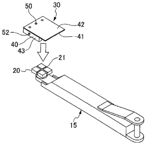
[0032] As illustrated in FIG. 5(A), the lift point alignment device
30 includes a mirror body 40 and light sources 50.
15 [0033] The mirror
body 40 is detachably attached to the vehicle
body holding tool 20. The mirror body 40 has a mirror plate 41, and a
surface of the mirror plate 41 is used as a mirror surface 42. In the
mirror body 40, the mirror surface 42 of the mirror plate 41 is arranged
upward while the mirror body 40 is attached to the vehicle body holding
tool 20. For example, the surface of the mirror plate 41 consisting of a
stainless steel plate may be subjected to mirror surface finishing and
used as the mirror surface 42.
[0034] The light sources 50 are provided in the mirror body 40 to
project spot-shaped light in a vertical direction toward the lower part of
the vehicle 1 from the mirror surface 42 of the mirror body 40 provided
in the vehicle body holding tool 20.
[0035] In this way, as illustrated in FIG. 3, the lift point
CA 02952399 2017-01-16
-11-
alignment device 30 observes an image A of the lift points 2 of the
vehicle 1 and an image B of the light sources 50 reflected in the mirror
surface 42 of the mirror body 40 by an operator M positioned at a side of
the vehicle 1. An alignment state of the vehicle body holding tool 20
with respect to the lift points 2 of the vehicle 1 is allowed to be
recognized based on a match state between the image A of the lift points
2 and the image B of the light sources 50 reflected in the mirror surface
42 of the mirror body 40 observed from the side of the vehicle 1 as
described above.
[00361 In the present embodiment, as described in the foregoing,
the vehicle body support 21 to be aligned to the lift points 2 of the
vehicle 1 is provided on the upper surface of the vehicle body holding
tool 20. In this instance, in the lift point alignment device 30, while
the mirror body 40 is attached to the vehicle body holding tool 20, the
light sources 50 provided in the mirror body 40 are installed at a
position aligned to a vertically upper portion of the vehicle body support
21 of the vehicle body holding tool 20.
[00371 Further, in the present embodiment, as described in the
foregoing, it is presumed that the vehicle body support 21 of the vehicle
body holding tool 20 forms a linear shape (a cross shape) aligned to the
linear lift points 2 (side seal) provided in the lower part of the vehicle 1.
The linear lift points 2 (side seal) provided in the lower part of the
vehicle 1 are specified by cutting off a lift central portion 2L of the side
seal in a concave shape (FIGS. 6(A) and 6(B)). In this instance, in the
lift point alignment device 30, a plurality of light sources (three light
sources in the present embodiment) 50 are installed on a straight line
aligned to the linear vehicle body support 21 of the vehicle body holding
CA 02952399 2017-01-16
¨12 ¨
tool 20. One central light source among the three light sources 50 is
aligned to a central position of the linear vehicle body support 21 of the
vehicle body holding tool 20.
[00381 Further, in the present embodiment, as illustrated in FIG.
5(A), the mirror body 40 of the lift point alignment device 30 includes
mounting frame portions 43 installed in a protruding manner at two
sides (two right and left sides) facing each other on a rear side of the
mirror surface 41. In addition, when the mirror body 40 is attached to
the vehicle body holding tool 20, each of the mounting frame portions 43
is attached on an outer circumferential portion of the rectangular
block-shaped vehicle body holding tool 20 to interpose two side surfaces
facing each other of the rectangular block-shaped vehicle body holding
tool 20 between the mounting frame portions 43.
[00391 Further, in the present embodiment, as illustrated in FIG.
5(A), the mirror body 40 of the lift point alignment device 30 includes a
mounting protrusion 44 installed in a protruding manner by being
arranged to be perpendicular to the mounting frame portion 43 between
the above-described two mounting frame portions 43, 43 on the rear
side of the mirror surface 41. In addition, when the mirror body 40 is
attached to the vehicle body holding tool 20, as illustrated in FIG. 5(C),
the mounting protrusion 44 is fit to the groove-shaped vehicle body
support 21 provided within an upper surface of the vehicle body holding
tool 20. The mirror body 40 is fixedly configured such that the
plurality of light sources 50 installed on the straight line is aligned to
the vertically upper portion of the linear vehicle body support 21 of the
vehicle body holding tool 20 by the presence of the two mounting frame
portions 43, 44 and the above-described mounting protrusion 44 while
CA 02952399 2017-01-16
¨13¨
the mirror body 40 is attached to the vehicle body holding tool 20.
[0040] In this instance, in the lift point alignment device 30, as
illustrated in FIG. 5(B), the light sources 50 consist of LEDs, and three
LEDs are incorporated in the mounting protrusion 44. In addition, the
lift point alignment device 30 incorporates a battery 51 such as a
button-type battery and a lighting switch 52 having a push button type,
etc. for the LEDs in the mounting frame portion 43. Further, an
electric circuit 53 that connects the light sources 50, the battery 51, and
the lighting switch 52 to each other is incorporated in the mirror body
40 (the mounting frame portion 43 and the mounting protrusion 44).
The battery 51 is hidden by a battery replacement cover 54 provided in
the mounting frame portion 43, and a battery may be replaced by
removing the cover 54. The battery 51 is fixed by a battery holder, and
a battery may be replaced even when an electric wiring process
(disconnection, connection) is not performed. The lighting switch 52
performs an alternate operation. An LED is switched ON when the
lighting switch 52 is pressed once, and the LED is switched OFF when
the lighting switch 52 is pressed once again.
[0041] The present embodiment has the following effects.
(a) When the mirror body 40 of the lift point alignment device 30
in which the light sources 50 are switched ON is attached to the vehicle
body holding tool 20 provided at the distal end of the lifting arm 15, 16,
and the vehicle body holding tool 20 of the lifting arm 15, 16 is inserted
into the lower part of the vehicle 1, items i and ii below result.
[0042] i. Light of the light sources 50 is vertically projected
toward the lower part of the vehicle 1 from the mirror surface 42 of the
mirror body 40 attached to the upper portion of the vehicle body holding
CA 02952399 2017-01-16
¨14¨
tool 20. In this instance, the image A of the lower part of the vehicle 1
and the image B of the light sources 50 projected onto the lower part of
the vehicle 1 are reflected in the mirror surface 42 of the mirror body 40.
[0043] ii. The operator M positioned on a side of the vehicle 1
may observe the image A of the lower part of the vehicle 1 and the
image B of the light sources 50 projected onto the lower part of the
vehicle 1, which are reflected in the mirror surface 42 of the mirror body
40, by reflection in the mirror surface 42. In this way, the operator M
may adjust a distal end position of the lifting arm 15, 16 such that the
image B of the light sources 50 reflected in the mirror surface 42 of the
mirror body 40 matches the image A of the lift points 2 of the lower part
of the vehicle 1 as illustrated in FIG. 6(A), thereby aligning the vehicle
body holding tool 20 to the lift points 2 of the lower part of the vehicle 1.
[0044] FIG. 6(A) illustrates a match state between the image A
of the lift points 2 and the image B of the light sources 50. The image
B of the three light sources 50 overlaps the image A of the lift points 2
having a linear shape. A position and a direction of the vehicle body
holding tool 20 are aligned to the lift points 2 of the vehicle 1.
[0045] FIG. 6(B) illustrates a mismatch state between the image
A of the lift points 2 and the image B of the light sources 50. Only the
image B of one light source 50 among the three light sources 50 overlaps
only a portion corresponding to the lift central portion 2L in the image A
of the lift points 2 having the linear shape. While a central position of
the vehicle body holding tool 20 matches the lift central portion 2L of
the lift points 2, a direction of the vehicle body holding tool 20 is not
aligned to the lift points 2.
[0046] Positions at which the image A of the lower part of the
CA 02952399 2017-01-16
¨15¨
vehicle 1 and the image B of the light sources 50 projected onto the
lower part of the vehicle 1 are reflected in the mirror surface 42 change
depending on an angle and the position at which the operator M views
the mirror surface 42 of the mirror body 40. However, light of the light
sources 50 is projected in the vertical direction toward the lower part of
the vehicle 1, and a mutual positional relation between the image A of
the lower part of the vehicle 1 and the image B of the light sources 50
projected onto the lower part of the vehicle 1 does not change.
Therefore, irrespective of a position from which the operator M views
the mirror surface 42 of the mirror body 40, the mutual positional
relation between the image A of the lower part of the vehicle 1 and the
image B of the light sources 50 projected onto the lower part of the
vehicle 1 may be viewed, and the vehicle body holding tool 20 may be
aligned to the lift points 2 in the lower part of the vehicle 1 as described
above.
[0047] At the time of lifting up the vehicle 1, the vehicle body
holding tool 20 may be put to the lift points 2 of the vehicle 1 by
removing the mirror body 40 of the lift point alignment device 30 from
the vehicle body holding tool 20, and lifting the vehicle body holding tool
20 of the lifting arm 15, 16 in the vertical direction.
[0048] The operator M may neither look into the dark lower part
of the vehicle 1 nor take a difficult work posture in which a head is
lowered in order to search for the lift points 2 in the lower part of the
vehicle 1, and may easily align the vehicle body holding tool 20 to the
lift points 2 in the lower part of the vehicle 1.
[0049] (b) While the mirror body 40 is attached to the vehicle
body holding tool 20, the light sources 50 provided in the mirror body 40
CA 02952399 2017-01-16
¨16 ¨
are configured to be aligned to the vehicle body support 21 of the vehicle
body holding tool 20. Therefore, when the distal end position of the
lifting arm 15, 16 is adjusted such that the image B of the light sources
50 reflected in the mirror surface 42 of the mirror body 40 matches the
image A of the lift points 2 in the lower part of the vehicle 1, the vehicle
body support 21 of the vehicle body holding tool 20 configured to be
aligned to the light sources 50 is naturally aligned to the lift points 2 in
the lower part of the vehicle 1.
[0050] (c) It is presumed that, when the vehicle body support 21
of the vehicle body holding tool 20 of the above-described item (b) forms
a linear shape aligned to the linear lift points 2 of the vehicle 1, the
plurality of light sources 50 is installed on a straight line aligned to the
linear vehicle body support 21 of the vehicle body holding tool 20.
Therefore, when the distal end position of the lifting arm 15, 16 is
adjusted through parallel movement and rotational movement such
that the image B of the plurality of light sources 50 installed on a
straight line reflected in the mirror surface 42 of the mirror body 40
matches the image A of the linear lift points 2 (side seal, etc.) in the
lower part of the vehicle 1, the linear vehicle body support 21 of the
vehicle body holding tool 20, to which the plurality of light sources 50 is
configured to be aligned, is aligned to the linear lift points 2 in the lower
part of the vehicle 1.
[0051] (d) The mirror body 40 of the above-described items (b)
and (c) includes the mounting frame portion 43 installed in the
protruding manner on a rear side of the mirror surface 42, and the
mounting frame portion 43 is attached on the outer circumferential
portion of the vehicle body holding tool 20 at the time of attaching the
CA 02952399 2017-01-16
¨17¨
mirror body 40 to the vehicle body holding tool 20. In this way, a state
in which the mirror body 40 is attached to the vehicle body holding tool
20 may be fixed, and the light sources 50 provided in the mirror body 40
may be reliably aligned to the vehicle body support 21 of the vehicle
body holding tool 20.
[0052] (e) The mirror body 40 of the above-described items (b) to
(d) includes the mounting protrusion 44 installed in the protruding
manner on a rear side of the mirror surface 42, and the mounting
protrusion 44 is fit to the groove-shaped vehicle body support 21
provided within an upper surface of the vehicle body holding tool 20 at
the time of attaching the mirror body 40 to the vehicle body holding tool
20. In this way, a state in which the mirror body 40 is attached to the
vehicle body holding tool 20 may be fixed, and the light sources 50
provided in the mirror body 40 may be reliably aligned to the
groove-shaped vehicle body support 21 of the vehicle body holding tool
20. When the distal end position of the lifting arm 15, 16 is adjusted
such that the image B of the light sources 50 reflected in the mirror
surface 42 of the mirror body 40 matches the image A of the lift points 2
in the lower part of the vehicle 1, the groove-shaped vehicle body
support 21 of the vehicle body holding tool 20 configured to be aligned to
the light sources 50 is naturally stably aligned to the lift points 2 in the
lower part of the vehicle 1.
[0053] co The light sources 50 of the lift point alignment device
include LEDs, and the mirror body 40 includes the battery 51 and
25 the lighting switch 52 for the LEDs. A carrying and handling property
of the lift point alignment device 30 may be improved.
[0054] FIGS. 7(A) and 7(B) is a modified example of the lift point
CA 02952399 2017-01-16
¨18¨
alignment device 30, and this modified example is different from the
above embodiment in that a mirror body 40 includes mounting frame
portions 43, 43 installed in a protruding manner at two right and left
sides facing each other on a rear side of a mirror plate 41, and includes
a mounting frame portion 45 installed in a protruding manner at one
front side on the rear side of the mirror plate 41 as illustrated in FIGS.
7(A) and 7(B). In addition, at the time of attaching the mirror body 40
to the vehicle body holding tool 20, the mounting frame portions 43, 45
are attached on three sides intersecting one another in an outer
circumferential portion of a rectangular block-shaped vehicle body
holding tool 20. In this way, the mirror body 40 is fixedly configured
such that a plurality of light sources 50 installed on a straight line is
aligned to a vertically upper portion of a linear vehicle body support 21
of the vehicle body holding tool 20 while the mirror body 40 is attached
to the vehicle body holding tool 20.
[0055] In FIGS. 7(A) and 7(B), the mirror body 40 of the lift
point alignment device 30 includes a connection frame 46 perpendicular
to the above-described two mounting frame portions 43, 43 on the rear
side of the mirror plate 41. The connection frame 46 of the mirror body
40 is configured to be aligned to the vertically upper portion of the
vehicle body support 21 of the vehicle body holding tool 20 while the
mirror body 40 is attached to the vehicle body holding tool 20, and three
light sources 50 forming a straight line are arranged on a center line of
the connection frame 46.
[0056] As heretofore explained, embodiments of the present
invention have been described in detail with reference to the drawings.
However, the specific configurations of the present invention are not
CA 02952399 2017-01-16
¨19¨
limited to the illustrated embodiments but those having a modification
of the design within the range of the presently claimed invention are
also included in the present invention. For example, the vehicle body
holding tool provided in the lifting arm may not have a rectangular
block shape, and may have a round disc shape.
[0057] The vehicle body holding tool may not include the
groove-shaped vehicle body support having the linear shape on the
upper surface thereof. The vehicle body holding tool may include a
hole-shaped vehicle body support in a central portion on the upper
surface.
[0058] The lift points of the vehicle may not have a linear shape
such as a side seal, and may have a surface shape.
[0059] The mirror body of the lift point alignment device may
include a mounting portion, which is detachably engaged with an outer
circumference of the vehicle body holding tool to regulate free
movement in a horizontal direction, on a rear side of the mirror plate.
[0060] The mirror surface of the mirror body may not be formed
by performing mirror surface finishing on the stainless steel plate.
[0061] The light source may not have a spot shape, and may
have a line shape. The light source is not restricted to an LED, and
may correspond to laser beam.
INDUSTRIAL APPLICABILITY
[0062] According to the invention, a vehicle body holding tool
provided in a lifting arm of a vehicle maintenance lift may be easily
aligned to lift points provide in a lower part of a vehicle.
REFERENCE SIGNS LIST
[0063] 1 vehicle
CA 02952399 2017-01-16
¨20-
2 lift point
vehicle maintenance lift
15, 16 lifting arm
vehicle body holding tool
5 21 groove-shaped vehicle body support
lift point alignment device
mirror body
42 mirror surface
43 mounting frame portion
10 44 mounting protrusion
mounting frame portion
light source
51 battery
52 lighting switch