Note: Descriptions are shown in the official language in which they were submitted.
CA 02952651 2016-12-16
WO 2016/000034 PCT/AU2015/050361
- 1 -
DEFORMATION MEASUREMENT METHOD AND APPARATUS
Background of the Invention
[0001] The present invention relates to a method and apparatus for measuring
deformation of
a body using optical fibre strain sensing techniques.
Description of the Prior Art
[0002] Deformations of objects or structures under applied loads or other
stimulus have
traditionally been measured using electrical strain gauges, which typically
include an
electrical conducting element configured to exhibit variable electrical
resistance properties
depending on a level of strain in a surface to which the strain gauge is
attached.
[0003] Techniques are also known for measuring strain along optical fibres
which can be
configured to exhibit variable optical responses depending on the level of
strain. Optical fibre
strain sensors can be desirable over traditional electrical strain gauges in a
range of
circumstances, including in situations where strain sensing is required
remotely from
electrical power sources or in harsh environments, such as where high
temperature conditions
are likely to be encountered. Optical fibre strain sensors can also allow
measurements to be
taken at multiple points along the length of a fibre.
[0004] A Fibre Bragg Grating (FBG) may be formed in a segment of an optical
fibre to
provide a strain sensitive element at a predetermined point along the length
of a fibre. An
FBG reflects particular wavelengths of light and transmits all others, with
the reflected
wavelengths being characterised by a Bragg wavelength. The Bragg wavelength
depends on
dimensional characteristics of the FBG and thus is sensitive to strain.
Accordingly, a strain of
the optical fibre can be measured based on a shift in the Bragg wavelength
compared to that
under known conditions. The Bragg wavelength may also shift due to thermal
changes in the
refractive index of the fibre and expansion/contraction of the optical fibre.
Multiple FBGs
can be formed in respective segments of the same optical fibre, each with
distinct Bragg
wavelengths, to allow multiple strain measurements using the same optical
fibre.
[0005] Alternative technologies for measuring strain along optical fibres are
also known. For
example, strain may be measured using techniques which detect scattering of
electromagnetic
CA 02952651 2016-12-16
WO 2016/000034 PCT/AU2015/050361
- 2 -
radiation along the length of an optical fibre, such as by Brillouin
scattering, Raman
scattering or Rayleigh scattering. These techniques can allow distributed
strain sensing along
a length of an optical fibre as opposed to discrete strain sensitive elements
formed by FBGs
or the like, although will typically require more sophisticated processing
equipment.
[0006] US 7,315,666 discloses a method and system for measuring pressure and
other
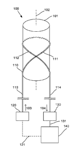
physical data, such as the temperature, elongation, torsion and bending at any
point along the
length of an elongate carrier tube by means of coiled optical fibers that are
embedded in the
wall of the tube such that deformation of the carrier tube induces strain in
each optical fiber.
In use a pulsed laser light source transmits a sequence of light pulses of a
selected
wavelength from an upstream end of each fiber into a coiled substantially
uniform light guide
channel provided by the optical fiber and a light sensor assembly detects any
shift in
wavelength of the light pulses backscattered from various locations along the
length of the
light guide channel. A signal processing assembly then calculates a strain
pattern along the
length of the fiber, and a pressure difference between the interior and
exterior of the tube, at
various locations along the length of the carrier tube. Preferably several
fibers are wound at
different pitch angles and in different directions and at different diameters
in the wall of the
carrier tube and the signal processing assembly calculates bending, torsion
and both radial
and axial deformation of the carrier tube on the basis of a comparison of the
strain patterns
induced on different optical fibers.
[0007] US 8,131,121 discloses an optical fiber pipeline monitoring system and
method. In
accordance with one aspect, a fiber surveillance system for monitoring a
pipeline is provided.
The surveillance system includes an optical fiber acoustically coupled to the
pipeline to
detect acoustic signals associated with vibrations or other activity near or
from the pipeline.
Optical energy is injected into the optical fiber and an optical detector
receives an optical
return-signal having certain characteristics resulting from vibrations
impinging on the optical
fiber. An analyzer is configured to determine operating information about the
pipeline based
on the optical return-signal. Two or more fibers can be acoustically coupled
to the pipeline
and arranged in varying configurations to yield greater resolution.
[0008] W02009/068907 discloses a pipe and a method of determining the shape of
a pipe.
The pipe has an optical fibre strain sensor embedded within it. The optical
fibre strain sensor
CA 02952651 2016-12-16
WO 2016/000034 PCT/AU2015/050361
- 3 -
comprises an optical fibre having an array of fibre Bragg gratings (FBG)
provided within it.
The FBGs are arranged in a spaced array along the fibre. The optical fibre
strain sensor is
helically wound, with a fixed helix pitch, around the axial length of the
pipe. The FBGs are
thereby arranged in a predetermined orientation relative to the axis of the
pipe. A method of
determining the shape of a pipe, including decoupling the effects of bending,
tension, torsion
and hoop strain on the strain measurements made by the FBGs and/or
interpolating the strain
measurements to obtain a fully distributed strain profile of the pipe.
[0009] The reference in this specification to any prior publication (or
information derived
from it), or to any matter which is known, is not, and should not be taken as
an
acknowledgment or admission or any form of suggestion that the prior
publication (or
information derived from it) or known matter forms part of the common general
knowledge
in the field of endeavour to which this specification relates.
Summary of the Present Invention
[0010] In a broad form the present invention seeks to provide apparatus for
measuring
deformation of an elongate body defining an axis, the apparatus including:
a) an optical fibre arranged relative to the body, the optical fibre
including:
i) a first strain sensitive optical fibre portion coupled to the body and at
least
partially aligned at a first angle relative to the axis; and,
ii) a second strain sensitive optical fibre portion coupled to the body and at
least
partially aligned at a second angle relative to the axis, the second angle
being
opposite to the first angle;
b) a radiation source connected to an end of the optical fibre, the radiation
source being
for supplying electromagnetic radiation to the optical fibre;
c) a sensor connected to an end of the optical fibre, the sensor being for
sensing
electromagnetic radiation received from the first and second optical fibre
portions;
and,
d) a processing device for determining the deformation of the body using the
sensed
electromagnetic radiation, the deformation including any axial or torsional
deformation.
[0011] Typically the processing device determines deformation of the body by:
CA 02952651 2016-12-16
WO 2016/000034 PCT/AU2015/050361
- 4 -
a) determining, using the sensed electromagnetic radiation:
i) a first strain indicator indicative of a first strain on the first
optical fibre portion;
and,
ii) a second strain indicator indicative of a second strain on the second
strain sensing
portion; and,
b) determining deformations of the body at least partially based on the first
and second
strain indicators.
[0012] Typically the processing device compares the first and second strain
indicators to
distinguish between axial and torsional deformations of the body.
[0013] Typically the processing device determines that the body is undergoing
an axial
deformation based on a common mode response of the first and second strain
indicators.
[0014] Typically the processing device determines that the body is undergoing
a torsional
deformation based on a differential response of the first and second strain
indicators.
[0015] Typically the optical fibre includes a third strain sensitive optical
fibre portion that is
thermally coupled to the body, wherein the processing device:
a) determines, using the sensed electromagnetic radiation, a coupled
temperature
indicator indicative of a temperature of the third optical fibre portion; and,
b) determines a temperature of the body based on the coupled temperature
indicator.
[0016] Typically the optical fibre further includes a fourth strain sensitive
optical fibre
portion that is mechanically and thermally decoupled from the body, wherein
the processing
device:
a) determines, using the sensed electromagnetic radiation, a decoupled
temperature
indicator indicative of a temperature of the fourth optical fibre portion;
and,
b) determines an ambient temperature based on the decoupled temperature
indicator.
[0017] Typically the processing device uses at least one temperature indicator
to determine a
temperature induced deformation of the body.
[0018] Typically the processing device determines axial and torsional
deformation at least in
part using the temperature induced deformation of the body.
CA 02952651 2016-12-16
WO 2016/000034 PCT/AU2015/050361
-5-
100191 Typically the fourth optical fibre portion is provided at a terminal
end of the optical
fibre.
[0020] Typically both the radiation source and the sensor are connected to a
proximal end of
the optical fibre.
[0021] Typically the received electromagnetic radiation is at least one of
transmitted and
reflected electromagnetic radiation from the optical fibre portions.
[0022] Typically each optical fibre portion has a different optical response
characteristic to
thereby allow respective strain indicators to be determined for each optical
fibre portion
using the sensed electromagnetic radiation.
[0023] Typically each optical fibre portion includes a fibre Bragg grating.
[0024] Typically each fibre Bragg grating has a predetermined Bragg
wavelength, such that
the strain of the respective strain element can be determined based on a shift
of the respective
Bragg wavelength.
[0025] Typically each strain sensitive optical fibre portion includes a
distributed strain
sensitive element defined by the optical fibre.
[0026] Typically each strain sensitive optical fibre portion is provided by
naturally occurring
microstructures within the optical fibre portions having predetermined optical
response
characteristics.
[0027] Typically each strain sensitive optical fibre portion generates a
strain indicator in
response to the supplied electromagnetic radiation by at least one of:
a) Brillouin scattering;
b) Raman scattering; and,
c) Rayleigh scattering.
[0028] Typically each strain sensitive optical fibre portion is provided by a
continuous
uniform grating.
CA 02952651 2016-12-16
WO 2016/000034 PCT/AU2015/050361
-6-
100291 Typically the radiation source supplies a pulse of electromagnetic
radiation and the
processing device determines respective strain indicators for each strain
sensitive optical
fibre portion based on a pulse response time.
[0030] Typically the sensor senses the received electromagnetic radiation
using at least one
of:
a) interferometry;
b) spectroscopy; and,
c) backscattering.
[0031] Typically at least the first and second optical fibre portions are
coupled to the body
using an adhesive.
[0032] Typically at least the first and second optical fibre portions are
coupled to the body in
a channel defined in a surface of the body.
[0033] Typically at least the first and second optical fibre portions are
integrally formed with
the body.
[0034] Typically the optical fibre is looped around the body to define first
and second fibre
lengths extending across the body from a looped fibre portion, the first fibre
length extending
at the first angle and including the first strain sensitive optical fibre
portion, and the second
fibre length extending at the second angle and including the second strain
sensitive optical
fibre portion.
[0035] Typically the optical fibre is looped around the body to define first
and second helical
aspects at least partially wound around the body in opposing winding
directions, the first
helical aspect including the first strain sensitive optical fibre portion, and
the second helical
aspect including the second strain sensitive optical fibre portion.
[0036] Typically each helical aspect includes a plurality of windings and a
plurality of strain
sensitive optical fibre portions.
[0037] Typically different ones of the windings have different pitch angles to
thereby align
strain sensitive optical fibre portions at different angles.
CA 02952651 2016-12-16
WO 2016/000034 PCT/AU2015/050361
-7-
100381 Typically the optical fibre runs along the body and is bent to define
first and second
fibre lengths extending from a bent portion, the first fibre length extending
at the first angle
and including the first strain sensitive optical fibre portion, and the second
fibre length
extending at the second angle and including the second strain sensitive
optical fibre portion.
[0039] Typically the optical fibre is wrapped circumferentially around the
body and includes
a wave defining rising and falling fibre lengths, the rising fibre length
including the first
strain sensitive optical fibre portion, and the falling fibre length including
the second strain
sensitive optical fibre portion.
[0040] Typically the optical fibre includes a plurality of waves, each wave
defining
respective rising and falling fibre lengths having respective strain sensitive
optical fibre
portions.
[0041] Typically different ones of the waves include respective rising and
falling fibre
lengths having different slope angles to thereby align strain sensitive
optical fibre portions at
different angles.
[0042] Typically the optical fibre includes a plurality of pairs of first and
second strain
sensitive optical fibre portions aligned at different respective first and
second angles.
[0043] In another broad form the present invention seeks to provide a method
for measuring
deformation of an elongate body defining an axis, the method including, in a
processing
device:
a) determining from a sensor connected to an end of an optical fibre, sensed
electromagnetic radiation received from first and second strain sensitive
optical fibre
portions, the first optical fibre portion being coupled to the body and at
least partially
aligned at a first angle relative to the axis and the second strain sensitive
optical fibre
portion coupled to the body and at least partially aligned at a second angle
relative to
the axis, the second angle being opposite to the first angle; and,
b) determining deformation of the body using the sensed electromagnetic
radiation, the
deformation including any axial or torsional deformation.
CA 02952651 2016-12-16
WO 2016/000034 PCT/AU2015/050361
- 8 -
Brief Description of the Drawings
[0044] An example of the present invention will now be described with
reference to the
accompanying drawings, in which: -
[0045] Figure 1A is a schematic diagram of a first example of apparatus for
measuring
deformation of a body;
[0046] Figure 1B is a front view of the body and an optical fibre arranged
relative to the
body as shown in Figure 1A;
[0047] Figure 2A is a schematic view of the body and the optical fibre of
Figure 1A, in
which an axial load is applied to the body to cause axial deformation of the
body;
[0048] Figure 2B is a schematic view of the body and the optical fibre of
Figure 1A, in which
a torsional load is applied to the body to cause torsional deformation of the
body;
[0049] Figure 3A is a plot depicting relationships between applied axial
loading and strain
indicators determined due to axial deformation of the body;
[0050] Figure 3B is a plot depicting relationships between applied torsional
loading and
strain indicators determined due to torsional deformation of the body;
[0051] Figure 4A is a schematic diagram of a second example of apparatus for
measuring
deformation of a body;
[0052] Figure 4B is a front view of the body and an optical fibre arranged
relative to the
body as shown in Figure 4A;
[0053] Figure 5 is a plot of example strain indicators under different loading
conditions
applied to a cylindrical body provided with apparatus for measuring
deformation of the body;
[0054] Figure 6 is a schematic diagram of a third example of apparatus for
measuring
deformation of a body;
[0055] Figure 7 is a schematic diagram of a fourth example of apparatus for
measuring
deformation of a body;
CA 02952651 2016-12-16
WO 2016/000034 PCT/AU2015/050361
-9-
100561 Figure 8A is a schematic diagram of a fifth example of apparatus for
measuring
deformation of a body;
[0057] Figure 8B is a front view of the body and an optical fibre arranged
relative to the
body as shown in Figure 8A;
[0058] Figure 9 is a schematic view of an optical fibre having three waves
with different
slope angles, in an unwrapped configuration;
[0059] Figure 10A is a plot of strain indicators under compression loading
conditions applied
to a cylindrical body provided with apparatus including the optical fibre of
Figure 9;
[0060] Figure 10B is a plot of a compression analysis of the strain indicators
of Figure 10A;
[0061] Figure 10C is a plot of a torque analysis of the strain indicators of
Figure 10A;
[0062] Figure 11A is a plot of strain indicators under torque loading
conditions applied to a
cylindrical body provided with apparatus including the optical fibre of Figure
9;
[0063] Figure 11B is a plot of a compression analysis of the strain indicators
of Figure 11A;
[0064] Figure 11C is a plot of a torque analysis of the strain indicators of
Figure 11A;
[0065] Figure 12A is a plot of example strain indicators under mixed loading
conditions
applied to a cylindrical body provided with apparatus including the optical
fibre of Figure 9;
[0066] Figure 12B is a plot of a compression analysis of the strain indicators
of Figure 12A;
and,
[0067] Figure 12C is a plot of a torque analysis of the strain indicators of
Figure 12A.
Detailed Description of the Preferred Embodiments
[0068] An example of apparatus 100 for measuring deformation of an elongate
body 101
defining an axis 102 will now be described with reference to Figures 1A and
1B.
[0069] In general terms, the apparatus 100 includes an optical fibre 110
arranged relative to
the body 101, a radiation source 120 connected to an end of the optical fibre
110, a sensor
CA 02952651 2016-12-16
WO 2016/000034 PCT/AU2015/050361
- 10 -
130 connected to an end of the optical fibre 110, and a processing device 140.
[0070] In particular, the optical fibre 110 includes a first strain sensitive
optical fibre portion
111 that is coupled to the body 101 and at least partially aligned at a first
angle ai relative to
the axis 102, and a second strain sensitive optical fibre portion 112 that is
also coupled to the
body 101 and at least partially aligned at a second angle a2 relative to the
axis. The second
angle a2 is opposite to the first angle ai as can be seen in Figure 1B.
[0071] The radiation source 120 is provided for supplying electromagnetic
radiation to the
optical fibre 110, as indicated by arrow 103 in Figure 1A, whilst the sensor
130 is provided
for sensing electromagnetic radiation received from the first and second
optical fibre portions
111, 112, as indicated by arrow 104 in Figure 1A.
[0072] The electromagnetic radiation can be from any region of the
electromagnetic
spectrum suitable for use with the optical fibre 110. Whilst the
electromagnetic radiation will
typically be in the form of light, having wavelengths ranging from the
infrared, visible and
ultraviolet light regions of the electromagnetic spectrum, it should be
appreciated that other
wavelengths may be used.
[0073] The processing device 140 is provided for determining the deformation
of the body
101 using the sensed electromagnetic radiation, where the deformation may
include any axial
or torsional deformation of the body.
[0074] It will be appreciated that the opposite angles ai, a2 of the
respective strain sensitive
optical fibre portions 111, 112 will cause each optical fibre portion 111, 112
to experience
different strains relative to one another, depending on the particular
deformation state of the
body 101.
[0075] For example, as illustrated in Figure 2A, an applied tensile axial load
P will typically
result in tensile strains Si, S2 in the respective optical fibre portions 111,
112. In the present
example, in which the angles ai, a2 are equal in magnitude and opposite in
direction, each of
the optical fibre portions 111, 112 will undergo substantially the same strain
S due to an
applied axial load P. This relationship between strains Si, S2 in the first
and second optical
fibre portions 111, 112 and applied axial loading is depicted in Figure 3A,
where tensile
loads and strains are indicated as positive and compressive loads and strains
are indicated as
CA 02952651 2016-12-16
WO 2016/000034 PCT/AU2015/050361
- 11 -
negative. In the present example, in which the angles al, az are equal in
magnitude and
opposite in direction, each of the optical fibre portions 111, 112 will have
substantially the
same strain response due to an applied axial load P.
[0076] In contrast, with regard to the example illustrated in Figure 2B,
applied torsional
moment M will result in opposing strains Si, S2 in the respective optical
fibre portions 111,
112. For instance, when the torsional moment is applied in a right-handed
direction as shown
in Figure 2B, this will result in a compressive strain Si in the first optical
fibre portion 111
and a tensile strain S2 in the second optical fibre portion 112. The
relationship between the
strains Si, S2 in the first and second optical fibre portions 111, 112 and
applied torsional
loading by way of moment M is depicted in Figure 3B, where right-handed
moments and
tensile strains are indicated as positive. In contrast to the strain response
due to an applied
axial load, each of the optical fibre portions 111, 112 will have
substantially opposite strain
responses due to an applied torsional moment M.
[0077] In view of these different strain responses to different types of
applied loads, it will be
appreciated that the arrangement of strain sensitive optical fibre portions
111, 112 can be
used to distinguish between axial and torsional deformations of the body.
Typically this is
facilitated by having the processing device 140 process the sensed
electromagnetic radiation
received from the first and second optical fibre portions 111, 112 (via the
sensor 130) to
determine values indicative of the strains Si, S2 in the strain sensitive
optical fibre portions
111, 112, and subsequently use these values to determine any axial or
torsional deformation
of the body based on known strain response relationships such as those
exemplified in
Figures 3A and 3B.
[0078] It should be understood that whilst having the first and second optical
fibre portions
111, 112 aligned at angles al, az of equal magnitude as discussed above will
generally be
convenient as this will allow simplified interpretation of the different
strain response
relationships, this is not essential and useful results may still be obtained
provided the angles
al, az are opposite in direction relative to the axis. It should also be
understood that the strain
response relationships of the optical fibre portions 111, 112 will not always
necessarily be the
same as discussed above, and may depend on factors such as the magnitude of
the angles al,
az and/or material properties of the body 101, such as Poisson's ratio. In any
event, it will be
CA 02952651 2016-12-16
WO 2016/000034 PCT/AU2015/050361
- 12 -
appreciated that the particular strain response relationships for an
arrangement of optical fibre
portions 111, 112 about a body can be predetermined, and any axial or
torsional deformation
of the body 101 can be determined based on the predetermined strain response
relationships.
[0079] In any event, it will be appreciated that the above described apparatus
100 can allow
axial and torsional deformations of the body 101 to be determined using only a
single optical
fibre arranged relative to the body 101. The other apparatus elements of the
radiation source
120, sensor 130 and processing device 140 can be provided remotely as long as
the radiation
source 120 and sensor 130 are each connected to an end of the optical fibre
110.
[0080] As per the example of Figure 1A, the radiation source 120 may be
connected to an
end of a first extended length 113 of the optical fibre 110 and the sensor 130
may be
connected to an end of a second extended length 114 of the optical fibre 110,
such that the
strain sensitive optical fibre portions can be deployed on a body 101 remotely
from the
radiation source 120, sensor 130 and processing device 140 by having the first
and second
extended lengths 113, 114 of the optical fibre 110 extend between the body 101
and the
radiation source 120 and sensor 130, respectively.
[0081] The radiation source 120 can thus supply electromagnetic radiation to
the optical fibre
110 via the first extended length 113 of the optical fibre 110 and
electromagnetic radiation
will be transmitted through the first and second strain sensitive optical
fibre portions 111, 112
and then be received by the sensor via the second extended length 114 of the
optical fibre
110. The sensed electromagnetic radiation can then be used by the processing
device 140 to
determine the deformation of the body 101.
[0082] However, those familiar with the art of fibre optics will appreciate
that connections to
each end of the optical fibre 110 are not necessarily required. For instance,
with regard to the
example of an alternative embodiment of apparatus 400 as shown in Figure 4A,
the apparatus
400 may use a single extended length 413 of the optical fibre 110 and have an
active sensor
unit 450 which incorporates the radiation source 120 and the sensor 130 and is
connected to
the processing device 140.
[0083] In particular, the radiation source 120 of the active sensor unit 450
can supply
electromagnetic radiation to the optical fibre 110 via the single extended
length 413 of the
CA 02952651 2016-12-16
WO 2016/000034 PCT/AU2015/050361
- 13 -
optical fibre 110 and electromagnetic radiation reflected from the first and
second strain
sensitive optical fibre portions 111, 112 will be received by the sensor 130
of the active
sensor unit 450, also via the single extended length 413 of the optical fibre
110. Again, the
sensed electromagnetic radiation can then be used by the processing device 140
to determine
the deformation of the body 101. Thus it will be understood that in some
embodiments only a
single length of optical fibre 110 may be extended between the body 101 and
the
sensing/processing equipment.
[0084] In either case, it will be appreciated that apparatus provided based on
the above
described can be particularly advantageous in allowing measurements of
deformations of a
body positioned remotely from sensing and processing equipment, and can
facilitate
deformation measurements in extreme environments without exposing sensitive
equipment to
potential harm.
[0085] For example, the above described techniques may be particularly
suitable for allowing
compressive and torsional deformations to be measured in a portion of deployed
coiled
tubing supporting a downhole drilling motor during drilling operations. In
these operations,
the coiled tubing will provide reaction forces against drilling loads and it
is desirable to
monitor the resulting deformations so as to ensure stresses in the support
structure do not
exceed safe operating parameters.
[0086] In such examples, the optical fibre portions 111, 112 can be fitted to
a portion of the
coiled tubing proximate to the drilling motor and one or two extended lengths
of the optical
fibre 110 can be extended up the drilling hole to the radiation source 120,
sensor 130 and
processing device 140 located above ground. It will be appreciated that the
length(s) of
optical fibre connecting the strain sensitive optical fibre portions 111, 112
to the sensing and
processing equipment can be housed inside the deployed tubing, and the
radiation source
120, sensor 130 and processing device 140 may be integrated with other
equipment for
deploying the coiled tubing and controlling the drilling operations.
[0087] In another example, the optical fibre portions 111, 112 may be arranged
about the
base of a pole, such as a light pole, to measure applied loads during
installation or ongoing
loading in use.
CA 02952651 2016-12-16
WO 2016/000034 PCT/AU2015/050361
- 14 -
[0088] In view of the above, it will be understood that the apparatus 100
enables a method
for measuring deformation of an elongate body 101 defining an axis 102, the
method
including, in a processing device 140, determining from a sensor 130 connected
to an end of
an optical fibre 110, sensed electromagnetic radiation received from first and
second strain
sensitive optical fibre portions 111, 112, the first optical fibre portion 111
being coupled to
the body 101 and at least partially aligned at a first angle al relative to
the axis 102 and the
second strain sensitive optical fibre portion 112 coupled to the body 101 and
at least partially
aligned at a second angle a2 relative to the axis 102, the second angle a2
being opposite to the
first angle al, and subsequently determining deformation of the body 101 using
the sensed
electromagnetic radiation, the deformation including any axial or torsional
deformation.
[0089] Further details regarding the above discussed techniques will now be
described along
with further optional features of suitable embodiments of the apparatus.
[0090] With regard to the embodiment of the apparatus 100 depicted in Figure
1A, it will be
appreciated that the sensor 130 may be connected to the processing device 140
as indicated at
131, to provide outputs based on the sensed electromagnetic radiation to the
processing
device 140 for processing.
[0091] The radiation source 120 may also optionally be connected to the
processing device
140 at 121, to enable the processing device 140 to control the supply of
electromagnetic
radiation to the optical fibre 110. This may not be essential for some methods
of interrogating
the strain sensitive optical fibre portions 111, 112 where a constant supply
of electromagnetic
radiation may be sufficient, although some other methods may require the
supply of
controlled pulses and / or wavelength variations of the electromagnetic
radiation in which
control and potentially feedback of the supply of electromagnetic radiation
may be needed.
[0092] A similar arrangement can be provided for in the example of Figure 4A,
where the
active sensor unit 450 may be connected to the processing device 140 as
indicated at 451, and
this connection may be unidirectional to only provide outputs of the sensor
130 to the
processing device 140, or bi-directional to allow the processing device 140 to
control at least
some functionalities of the active sensor unit 450.
CA 02952651 2016-12-16
WO 2016/000034 PCT/AU2015/050361
- 15 -
[0093] In some embodiments, the processing unit 140 and the active sensor unit
450 may
also be integrated into a single unit. Any combination of the radiation source
120, sensor 130,
processing unit 140 may be housed in a common enclosure and therefore appear
as a single
unit. However, it will be appreciated this is not essential, and different
elements of the
apparatus 100 may or may not be integrated depending on requirements.
[0094] In some embodiments, the processing device 140 determines deformation
of the body
101 by determining, using the sensed electromagnetic radiation, a first strain
indicator
indicative of a first strain S1 on the first optical fibre portion 111 and a
second strain indicator
indicative of a second strain S2 on the second strain sensing portion 112, and
subsequently
determining deformations of the body 101 at least partially based on the first
and second
strain indicators.
[0095] These strain indicators may be determined based on the particular
technique used to
provide the strain sensitive optical fibre portions 111, 112. For instance, in
some examples,
the strain sensitive optical fibre portions 111, 112 are provided by forming
particular strain
sensitive elements in segments of the optical fibre 110 at known locations,
and with
respective known strain response characteristics so that the strain indicators
for each strain-
sensitive optical fibre portions 111, 112 can be determined based on these
characteristics. For
example, the strain-sensitive optical fibre portions 111, 112 may be formed to
have particular
wavelengths reflected but other wavelengths transmitted, depending on strain.
[0096] Alternatively, the processing device 140 may use other techniques to
determine the
strain indicators. For example, a pulse of electromagnetic radiation at a
predetermined
wavelength may be supplied into the optical fibre 110 and the processing
device 140 may be
configured to analyse sensed electromagnetic radiation that has been reflected
from
microstructures within the optical fibre 110. Changes in the wavelength or
phase of the
reflected electromagnetic radiation will be indicative of strains in the
optical fibre 110. Time
delays of the reflections of the pulse from different portions of the optical
fibre may be used
to pin-point the location along the optical fibre 110 at which the change has
taken place, so
that strain indicators for particular strain-sensitive optical fibre portions
111, 112 of the
optical fibre 110 can be determined. In such cases the apparatus 100 may
require calibration
based on the particular optical fibre 110 being used before it can provide
reliable results,
CA 02952651 2016-12-16
WO 2016/000034 PCT/AU2015/050361
- 16 -
whereas forming particular strain sensitive elements may reduce or eliminate
the need to
calibration. Whilst it will be understood that this example technique operates
in the optical
time domain, it will be appreciated that other techniques may operate in the
optical frequency
domain. For instance, measured signals may be converted into the frequency
domain using a
Fourier transform or the like, allowing frequency domain signal processing
techniques to be
applied.
[0097] It will be appreciated that a range of other techniques may be used
other than those
described above may be used to determine the strain indicators, and examples
of suitable
techniques will be described in further detail below.
[0098] In any event, the processing device 140 may compare the first and
second strain
indicators to distinguish between axial and torsional deformations of the body
101. For
instance, these comparisons can be made in view of known strain responses of
the respective
strain sensitive optical fibre portions 111, 112 as shown in Figures 3A and
3B.
[0099] For example, the processing device 140 may determine that the body 101
is
undergoing an axial deformation based on a common mode response of the first
and second
strain indicators. Similarly, the processing device 140 may determine that the
body 101 is
undergoing a torsional deformation based on a differential response of the
first and second
strain indicators.
[0100] Figure 5 shows a plot illustrating comparisons between the first and
second strain
indicators corresponding to respective first and second strains Si and S2 in
the first and
second strain sensitive optical fibre portions 111, 112. The x-axis represents
time whilst the
y-axis represents a strain indicator value in the form of a shift in a
characteristic wavelength
of light reflected from each strain sensitive optical fibre portions 111, 112,
so that the
respective curves correspond to the first and second strain indicators
corresponding to the
first and second strains Si and S2 (as marked) over a period of time during
which different
types of loading were applied to the body 101.
[0101] At 501, there are no applied loads and the strain indicator values
corresponding to the
first and second strains Si and S2 are approximately zero. However, when
compression loads
are applied at 502 and 503, there is a common mode response of the first and
second strain
CA 02952651 2016-12-16
WO 2016/000034 PCT/AU2015/050361
- 17 -
indicators corresponding to compressive first and second strains Si and S2.
Torque loads are
later applied in subsequently alternating directions at 503, 504, 505, 506,
resulting in
differential responses of the first and second strain indicators corresponding
to strains Si and
S2 in opposing directions.
[0102] The apparatus 100 not only allows axial and torsional deformations to
be
distinguished, but can also allow combinations of such deformations to be
determined. For
instance, a combination of compression and torque loading will result in a
complex
deformation of the body 101 depending on the relative magnitudes of the
respective loads.
However, the processing device 140 can be configured to determine the
respective
contributions due to axial and torsional deformations based on the common mode
and
differential responses of the first and second strain indicators.
[0103] With reference still to Figure 5, it is noted that the compression
events 502 and 503
cause a differential response component in addition to the common mode
response
component, which indicates a combination of axial and torsional deformations.
This can is
believed to be due to the particular manner of generating the compression
loading in the
experimental apparatus, in which a slight misalignment of applied axial loads
could result in
non-axial deformations.
[0104] Particular embodiments may include additional strain sensitive optical
fibre portions
which can allow for further expanded functionality.
[0105] For example, with regard to the alternative embodiment of the apparatus
400 as
shown in Figures 4A and 4B, the optical fibre 110 includes a third optical
fibre portion 415
mechanically decoupled from the torques and strains applied to the body 101,
but thermally
connected to the body 101, as can be best appreciated with regard to Figure
4B. The third
optical fibre portion 415 may be thermally connected to the body 101 using,
for example, a
suitable thermal interface material. In some examples, the third optical fibre
portion 415 may
be mechanically connected to the body 101 without being affected by torques
and strains,
such as by bonding the third optical fibre portion 415 to a section of the
body 101 that is
relieved or cut away from the main portion of the body 101 along each side of
the optical
fibre portion 415 and across one end of the third optical fibre portion 415,
but still attached to
the main portion of the body 101 at one end.
CA 02952651 2016-12-16
WO 2016/000034 PCT/AU2015/050361
- 18 -
[0106] In this example, the processing device 140 may additionally determine,
using the
sensed electromagnetic radiation from the sensor 130, a coupled temperature
indicator
indicative of a temperature of the third optical fibre portion 415, and then
determine a
temperature of the body 101 based on the coupled temperature indicator. As
explained further
below, this may allow a temperature of the body 101 to be determined.
[0107] The third optical fibre portion 415 may be a further strain sensitive
optical fibre
portion, which is effectively decoupled from axial and torsional deformation
modes, but can
undergo strains due to thermal expansion or contraction of the body 101 or of
the optical
fibre 110 itself due to temperature changes. Accordingly, the coupled
temperature indicator
may be indicative of a third strain S3 on the third optical fibre portion 415,
which can be
treated as an indication of temperature-based strain of the body 101.
[0108] It is acknowledged that the first and second strain indicators
indicative of the strains
Si, S2 on the first and second optical fibre portion 111, 112 may also
indicate temperature-
based strains to some extent. However, the contribution to the strains Si, S2
due to
temperature effects can effectively be compensated for in the determination of
axial and
torsional deformations, because the temperature-based strain components can be
isolated
based on knowledge of the third strain S3 which is based on temperature only.
It will be
appreciated that this can be particularly useful when the body 101 is located
in temperature
instable environments. Determining the temperature from the mechanically
decoupled third
optical fibre portion 415 can also avoid spurious strains due to other
deformation types such
as bending or due to transverse stretching/contracting of the body as a result
of applied axial
loading, due to the Poisson effect.
[0109] Accordingly, the processing device may use the coupled temperature
indicator to
determine a temperature induced deformation of the body 101. Subsequently, the
processing
device 140 may determine axial and torsional deformation of the body 101 at
least in part
using the temperature induced deformation of the body 101.
[0110] It should be understood that temperature changes will also cause
changes in the
refractive index of the optical fibre 110. Such refractive index changes may
result in different
characteristic responses to electromagnetic radiation supplied to the third
optical fibre portion
415, which could additionally or alternatively be used to determine the
temperature,
CA 02952651 2016-12-16
WO 2016/000034 PCT/AU2015/050361
- 19 -
depending on the configuration of the third optical fibre portion 415. Thus,
the third optical
fibre portion 415 may also allow for temperature measurements without
necessarily requiring
a strain sensitive optical fibre portion. Despite this, techniques for
providing a strain sensitive
optical fibre portion, such as by providing fibre Bragg gratings, can also
provide a suitable
temperature-sensitive optical fibre portion, and thus, the third optical fibre
portion 415 will
generally be provided in the form of an additional strain sensitive optical
fibre portion.
[0111] The third optical fibre portion 415 may be conveniently located in a
loop of the
optical fibre 110 between respective lengths of the optical fiber 110
including the first and
second optical fibre portions 111, 112. Although this looped arrangement of
the optical fibre
110 is not essential, it will be appreciated that this can be a convenient way
of arranging
portions of the optical fibre 110 on the body 101 which are aligned with
opposite angles
relative to the axis, and it is noted that a similar looped arrangement is
used in the first
example of Figures 1A and 1B.
[0112] In further examples, the optical fibre 110 may include further optical
fibre portions
that might or might not be mechanically and thermally decoupled from the body
101. The
processing device 140 may determine, using the sensed electromagnetic
radiation, additional
indicators indicative of a state of the optical fibre portion or a stimulus
applied to the optical
fibre portion. These indicators may be used by the processing device 140 to
determine
additional parameters such as ambient temperature, pressure, strain, presence
of gases and/or
chemical elements, acceleration or any other parameters for which optical
fibre sensing
techniques can be used.
[0113] In one example, the optical fibre 110 may include a fourth optical
fibre portion 416
that is mechanically and thermally decoupled from the body, as also shown in
Figures 4A and
4B. In this case, the processing device 140 may determine, using the sensed
electromagnetic
radiation, a decoupled temperature indicator indicative of a temperature of
the fourth optical
fibre portion 416. This decoupled temperature indicator may be used by the
processing
device 140 to determine an ambient temperature. As per the third optical fibre
portion 415,
the fourth optical fibre portion 416 may be conveniently provided using
another strain
sensitive optical fibre portion which will typically also have temperature-
sensitive response
characteristics.
CA 02952651 2016-12-16
WO 2016/000034 PCT/AU2015/050361
- 20 -
[0114] It will be appreciated that the ambient temperature determined using a
decoupled
temperature indicator may be used to compensate for temperature-based strain
components in
the first and second optical fibre portion 111, 112 instead of determining the
temperature of
the body 101 using the coupled temperature indicator. However, in some cases
it can be
beneficial to determine both the ambient temperature and the temperature of
the body 101,
such as to determine the extent of localised heating of the body 101 above the
ambient
temperature.
[0115] As depicted in Figures 4A and 4B, the fourth optical fibre portion 416
may be
provided at a terminal end of the optical fibre 110, particularly in
embodiments where an
active sensor unit 450 incorporating the radiation source 120 and sensor 130
is used so that
only one end of the optical fibre needs to be extended to connect to other
equipment.
Accordingly, both the radiation source 120 and the sensor 130 will be
connected to a
proximal end of the optical fibre 110. It will be appreciated that such an
arrangement may
require the sensor 130 to be configured to sense electromagnetic radiation
reflected from the
different optical fibre portions 111, 112, 415, 416.
[0116] In any case, as mentioned above, the sensed electromagnetic radiation
received by the
sensor from each of the optical fibre portions 111, 112, 415, 416 will
generally be either
transmitted or reflected from the optical fibre portions 111, 112, 415, 416.
[0117] Each optical fibre portion 111, 112, 415, 416 will preferably have a
different optical
response characteristic to thereby allow respective strain or temperature
indicators to be
determined for each optical fibre portion 111, 112, 415, 416 using the sensed
electromagnetic
radiation.
[0118] In some embodiments, each optical fibre portion 111, 112, 415, 416 may
include a
fibre Bragg grating which exhibits strain-dependent
reflectivity/transmissivity characteristics.
Typically, each fibre Bragg grating will be formed having a predetermined
Bragg wavelength
(which characterises the particular wavelengths of light reflected/transmitted
through the
fibre Bragg grating), such that the strain of the respective strain element
can be determined
based on a shift of the respective Bragg wavelength.
CA 02952651 2016-12-16
WO 2016/000034 PCT/AU2015/050361
-21 -
[0119] As discussed above, the refractive index of the optical fibre 110 may
also be sensitive
to temperature changes. This may in turn result in temperature-dependent
reflectivity/transmissivity characteristics. In the case of fibre Bragg
gratings, it is noted the
Bragg wavelength is defined by the formula
¨Bragg = n * L, where n is the refractive index and
L is the period of the Bragg structure), such that the characteristic Bragg
wavelength will
undergo changes based on strain-induced extension/contraction of the Bragg
structure or
temperature-induced changes in the refractive index.
[0120] Persons skilled in the art will be aware that techniques for providing
a strain sensitive
element in an optical fibre using a fibre Bragg grating or other analogous
techniques for
providing an optical fibre strain sensor are well established in the art, and
as such any known
technique in this regard may be used.
[0121] Whilst configuring the optical fibre portions 111, 112, 415, 416 to
have different
optical response characteristics can assist in allowing determination of the
respective strain or
temperature indicators, in some alternative embodiments the optical fibre
portions 111, 112,
415, 416 may have the same or similar optical response characteristics, and
other techniques
may be used to determine the respective strain or temperature indicators. For
instance, a pulse
of electromagnetic radiation may be supplied by the radiation source 120 and
the time taken
for reflected electromagnetic radiation to be received can be used to
distinguish respective
strain or temperature indicators for the different optical fibre portions 111,
112, 415, 416.
[0122] In other alternative embodiments, each strain sensitive optical fibre
portion 111, 112,
415, 416 may include a distributed strain sensitive element defined by the
optical fibre 110.
For example, each strain sensitive optical fibre portion 111, 112, 415, 416
may be provided
by naturally occurring microstructures within the optical fibre portions 111,
112, 415, 416
having predetermined optical response characteristics.
[0123] In such embodiments, each strain sensitive optical fibre portion 111,
112, 415, 416
may generate a strain indicator in response to the supplied electromagnetic
radiation due to
scattering of the electromagnetic radiation, such as by Brillouin scattering,
Raman scattering
or Rayleigh scattering. It will be appreciated that these embodiments may
require a more
sophisticated processing device 140 and potentially extensive calibration of
the apparatus to
account for the particular properties of the optical fibre 110. However, the
need for forming
CA 02952651 2016-12-16
WO 2016/000034 PCT/AU2015/050361
- 22 -
discrete fibre Bragg gratings in the optical fibre 110 will be removed, and
the associated
benefits of this will be greater if additional strain sensitive optical fibre
portions are required
to increase the resolution of the system or allow the determination of
deformations at many
different points along the body 101.
[0124] Brillouin and Raman scattering techniques work based on changes in the
phonon
energy in the optical fibre 110 at given locations. Electromagnetic radiation
with a
predetermined wavelength supplied into the optical fibre 110 is reflected at a
different
wavelength that is determined by the local phonon energy. The phonon energy is
modified by
changes in temperature and/or strain applied to the fibre. Hence the local
strain/temperature
applied to the optical fibre 110 can be determined by analysing the wavelength
shift of the
reflected light. The location of a given strain is determined by sampling the
reflected light at
a given time after the pump pulse is launched. The location is determined by
the time delay
and the speed of light in the optical fibre 110.
[0125] In other embodiments, distributed strain sensitive elements may be
defined in the
form of a continuous uniform grating, such as fibre Bragg grating extending
along a length of
the optical fibre 110. Such an arrangement can allow techniques to be used
which are a
hybrid of the discrete and distributed techniques above discussed, allowing a
compromise
between the processing efficiency of the discrete techniques and the available
resolution of
the distributed techniques.
[0126] In one example using a continuous uniform grating, the radiation source
120 supplies
a pulse of electromagnetic radiation and the processing device 140 determines
respective
strain indicators for each strain sensitive optical fibre portion based on a
pulse response time
of the sensed electromagnetic radiation received by the sensor 130. It will be
understood that
this can allow signals received from different portions of the continuous
uniform grating to
be distinguished based on the time taken for these to reach the sensor 130,
rather than by
relying on different optical response characteristics for each portion.
[0127] The radiation source 120 may be provided using any suitable source of
electromagnetic radiation of the appropriate wavelength spectrum for
interrogating the strain
sensitive optical fibre portion 111, 112, 415, 416. For example, in
embodiments using fibre
Bragg gratings having particular Bragg wavelengths, the radiation source 120
should be
CA 02952651 2016-12-16
WO 2016/000034 PCT/AU2015/050361
- 23 -
configured to supply a spectrum of electromagnetic radiation covering the
respective Bragg
wavelengths and with additional bandwidth to accommodate any shifts in the
Bragg
wavelengths that may occur due to deformations of the body 101. Suitable
radiation sources
may be provided using a Light Emitted Diode (LED), a tuneable laser or any
other suitable
source of light or other forms of electromagnetic radiation.
[0128] Alternatively, the radiation source 120 may be of a narrowband nature
selected to
coincide with the edge of one or more of the fibre Bragg gratings. In this
instance, a strain
applied to a fibre Bragg grating will shift its spectral profile and hence
change the intensity of
the reflected narrowband light.
[0129] The sensor 130 may sense the received electromagnetic radiation using
at least one of
interferometry, spectroscopy and backscattering. In one example, the sensor
130 may be
provided in the form of an optical spectrum analyzer which uses reflective
and/or refractive
or diffractive techniques to separate out the wavelengths of electromagnetic
radiation
received from the optical fibre portions 111, 112, 415, 416, and subsequently
uses an electro-
optical detector to measure the intensity of the electromagnetic radiation at
different
wavelengths. The output of this spectroscopy technique can then be provided to
the
processing device 140 to allow strain indicators to be determined as discussed
above and to
subsequently allow the deformation of the body 101 to be determined.
[0130] It is noted that fibre Bragg grating techniques typically use
reflection although
transmission can be used if needed, where the characteristic Bragg wavelength
is determined
based on wavelengths that have effectively been filtered during transmission
rather than
wavelengths that have been reflected. It is also noted that Brillouin
scattering, Raman
scattering and Rayleigh scattering are backscattered techniques. Brillouin
Optical Time
Domain Analysis may be used by supplying pump radiation from one end of the
optical fibre
110 and supplying probe radiation from the other end. Alternatively, Optical
Frequency
Domain Reflectometry (OFDR) may be used, which is a reflective technique.
[0131] The particular configuration of the processing device 140 may depend to
some extent
on the form of the sensor 130 being used and the resulting form of the output
provided to the
processing device 140. For example, in the example in which the sensor 130 is
provided in
the form of an optical spectrum analyzer, the output may be in the form of
electrical signals
CA 02952651 2016-12-16
WO 2016/000034 PCT/AU2015/050361
- 24 -
representing the intensity of the electromagnetic radiation at respective
wavelengths, and
additional equipment such as an analogue to digital converter may be required
to allow
digital processing of the output by the processing device 140. Alternatively,
the sensor 130
may be configured to directly output digital data indicating the intensity of
the sensed
electromagnetic radiation at different wavelengths, which can then be readily
processed by
the processor of a general purpose computer system configured with suitable
processing
instructions.
[0132] Accordingly, the nature of the processing device 140 and its
functionality will vary
depending on particular requirements of the apparatus. In one particular
example, the
processing device may include at least one processor, a memory, an optional
input/output
device, such as a keyboard and/or display, and an external interface for
allowing the output
from the sensor to be received. In use, the processor executes instructions in
the form of
applications software stored in the memory to perform required processes, such
as
determining strain indicators and comparing these for determining deformations
of the body
101. Thus, actions performed by the processing device 140 may be performed by
the
processor in accordance with instructions stored as applications software in
the memory
and/or input commands received via the input/output device. The applications
software may
include one or more software modules, and may be executed in a suitable
execution
environment, such as an operating system environment, or the like.
[0133] Accordingly, it will be appreciated that the processing device 140 may
be formed
from any suitable processing system, such as a suitably programmed computer
system, PC,
lap-top, hand-held PC, server, or the like. In one particular example, the
processing device is
a standard processing system such as an Intel or AMD Architecture based
processing system,
which executes software applications stored on non-volatile (e.g., hard disk)
storage,
although this is not essential. However, it will also be understood that the
processing device
140 could be or could include any electronic processing device such as a
microprocessor,
microchip processor, logic gate configuration, firmware optionally associated
with
implementing logic such as an FPGA (Field Programmable Gate Array), or any
other
electronic device, system or arrangement.
CA 02952651 2016-12-16
WO 2016/000034 PCT/AU2015/050361
- 25 -
[0134] In some embodiments, the processing device 140 may be provided along
with the
sensor 130 and optionally the radiation source 120 as part of an integrated
processing system
that is purpose-built for use with the apparatus 100.
[0135] As mentioned above, at least the first and second optical fibre
portions 111, 112 are
coupled to the body 101, such that they will undergo strains corresponding to
underlying
strains of the portion of the body 101 to which the optical fibre portions
111, 112 are
coupled. In some embodiments, the optical fibre portions 111, 112 are coupled
to respective
surfaces of the body 101 using an adhesive. In other embodiments, the optical
fibre portions
111, 112 might be directly embedded is the body 101, particularly if the body
101 is formed
from a composite material.
[0136] Although the optical fibre portions 111, 112 may be simply coupled to
an outer
surface of the body 101, this might leave the optical fibre 110 prone to
damage in some
applications, and accordingly, in some examples, at least the first and second
optical fibre
portions 111, 112 may be coupled to the body 101 in a channel defined in the
surface of the
body 101. In some examples, the channel may be defined in a pattern across the
surface of
the body 101 to at least the portion of the optical fibre 110 arranged on the
body 101 to be
recessed inside the channel. Accordingly, only the extended length(s) of the
optical fibre 110
for connections to the radiation source 120 and/or sensor 130 might protrude
from the
channel. It will be appreciated that other forms of local relief of material
of the body 101
immediately beneath or around the optical fibre portions may be used.
Alternatively, at least
a portion of the optical fibre 110 may be covered by a coating applied to the
body 101.
[0137] In other embodiments, at least the optical fibre portions 111, 112 may
be integrally
formed with the body 101. For example, the body 101 may be formed from a
composite
material including wound fibres, such as glass or carbon fibres, which are
wound and bound
with a resin or the like. One or more portions of the optical fibre 110
including the optical
fibre portions 111, 112 may be incorporated with the windings to thereby embed
the optical
fibre portions 111, 112 in the composite structure of the body 101.
[0138] It will be appreciated that the examples above generally depict looped
arrangements
in which the optical fibre 110 is looped around the body 101 to define first
and second fibre
lengths extending across the body 101 from a looped fibre portion, the first
fibre length
CA 02952651 2016-12-16
WO 2016/000034 PCT/AU2015/050361
- 26 -
extending at the first angle al and including the first strain sensitive
optical fibre portion 111,
and the second fibre length extending at the second angle a2 and including the
second strain
sensitive optical fibre portion 112. However, it should be understood that
other arrangements
are possible.
[0139] In some examples, such as the embodiment of the apparatus 600 shown in
Figure 6,
greater numbers of strain sensitive optical fibre portions may be coupled to
the body, such as
by providing the optical fibre 110 in a coiled arrangement in which a
plurality of strain
sensitive optical fibre portions are aligned with each of the first and the
second angle. In this
example, strain sensitive optical fibre portions 111, 615, 617, 619, 621, 623,
625 and 627 are
aligned with the first angle along a first helically wound portion of the
optical fibre 110, and
strain sensitive optical fibre portions 112, 616, 618, 620, 622, 624, 626 and
628 are aligned
with the second angle along a second helically wound portion of the optical
fibre 110, which
is wound about the body 101 in an opposite direction compared to the first
helically wound
portion.
[0140] In other words, the optical fibre 110 may be arranged in a dual helix
arrangement in
which the optical fibre 110 is looped around the body 101 to define first and
second helical
aspects at least partially wound around the body 101 in opposing winding
directions, the first
helical aspect including the first strain sensitive optical fibre portion 111,
and the second
helical aspect including the second strain sensitive optical fibre portion
112. Each helical
aspect may include a plurality of windings and a plurality of strain sensitive
optical fibre
portions
[0141] It will be appreciated that the use of additional strain sensitive
optical fibre portions,
provided at different positions around the body 101, can allow further
information regarding
the deformation of the body 101 to be determined. For example, suitably placed
strain
sensitive optical fibre portions may allow bending deformations to be
determined along with
axial and torsional deformations. Furthermore, axial and torsional
deformations at different
positions along a length of the body 101 may also be determined, providing
improved
resolution for determining variations of deformations of the body 101, such as
due to high
localised loadings in particular parts of the body 101.
CA 02952651 2016-12-16
WO 2016/000034 PCT/AU2015/050361
- 27 -
[0142] In an alternative embodiment of the apparatus 600 the helical wound
portion of the
fibre 110 might be coupled to the body 101 with a variable pitch arrangement.
In other
words, different ones of the windings may have different pitch angles to
thereby align strain
sensitive optical fibre portions at different angles. It will be appreciated
that this results in
strain sensitive optical fibre portions with different sensitivity responses
and therefore allows
the development of a highly sensitive wide range deformation measurement
device.
Accordingly, in some preferred examples, the optical fibre 110 may include a
plurality of
pairs of first and second strain sensitive optical fibre portions aligned at
different respective
first and second angles, in order to provide a number of effective sensors
with different
effective sensitivities in the same optical fibre 110.
[0143] It should also be understood that the particular arrangement of the
optical fibre 110 in
relation to the body 101 can vary provided at least the first and second
strain sensitive optical
fibre portions 111, 112 are provided with the required angular alignments
relative to the axis
102. Accordingly, whilst the Figures discussed above show the optical fibre
110 provided in
a looped or helically coiled arrangement relative to the body 101, this is not
essential and
other arrangements of the optical fibre 110 may be used to provide similar
functionality as
discussed above.
[0144] In this regard, Figure 7 shows an example in which the optical fibre
110 is bent
between the first and second strain sensitive optical fibre portions 111, 112
so as to define
portions aligned with the opposite first and second angles without requiring
looping of the
optical fibre 110 around the body 101 or crossing segments of the optical
fibre 110. In other
words, in a bent arrangement, the optical fibre 110 runs along the body 101
and is bent to
define first and second fibre lengths extending from a bent portion, the first
fibre length
extending at the first angle al and including the first strain sensitive
optical fibre portion 111,
and the second fibre length extending at the second angle az and including the
second strain
sensitive optical fibre portion 112.
[0145] In another example, the optical fibre 110 may be provided in a wrapped
arrangement
as shown in Figures 8A and 8B, in which the optical fibre 110 is wrapped
circumferentially
around the body 101 and includes a wave defining rising and falling fibre
lengths, the rising
CA 02952651 2016-12-16
WO 2016/000034 PCT/AU2015/050361
- 28 -
fibre length including the first strain sensitive optical fibre portion 111,
and the falling fibre
length including the second strain sensitive optical fibre portion 112.
[0146] As can be better appreciated in Figure 8B, the first and second strain
sensitive optical
fibre portions 111, 112 may be located in the rising and falling fibre lengths
respectively in a
generally mirrored arrangement, so that the first and second strain sensitive
optical fibre
portions 111, 112 are aligned at opposing first and second angles al, az. The
first extended
length 113 and the second extended length 114 may extend away from the body
101 from the
same position. In some applications, where a large elongation of the body 101
is expected, it
may be desirable to use such a wave-shaped arrangement rather than a looped or
helical
arrangement as discussed above to mitigate high strains in parts of the
optical fibre 110 in
use.
[0147] In extensions of this wrapped arrangement, the optical fibre 110 may
include a
plurality of waves within the same circumferential wrap around the body 101,
each wave
defining respective rising and falling fibre lengths having respective strain
sensitive optical
fibre portions 111, 112. In some embodiments, different ones of the waves may
include
respective rising and falling fibre lengths having different slope angles to
thereby align strain
sensitive optical fibre portions at different angles. This can facilitate
measurements with
different sensitivities at the same longitudinal position along the body 101.
[0148] An example of an optical fibre 900 having three waves with different
slope angles is
shown in Figure 9, in an unwrapped configuration (i.e. removed from the body
101 and
flattened into a planar arrangement whilst retaining the wave geometry). A
first wave on the
left of the optical fibre 900 as depicted includes a first pair of strain
sensitive optical fibre
portions 911, 912 on its rising and falling fibre lengths to define a first
effective sensor A.
The strain sensitive optical fibre portions 911, 912 are aligned at first and
second angles aiA,
azA and undergo tensile strains SiA, S2A. In a similar manner, a second wave
on the centre of
the optical fibre 900 includes a second pair of strain sensitive optical fibre
portions 913, 914
on its rising and falling fibre lengths to define a second effective sensor B.
The strain
sensitive optical fibre portions 913, 914 are aligned at first and second
angles au3, a2B and
undergo tensile strains SIB, S2B. Finally, a third wave on the right of the
optical fibre 900 as
depicted includes a third pair of strain sensitive optical fibre portions 915,
916 on its rising
CA 02952651 2016-12-16
WO 2016/000034 PCT/AU2015/050361
- 29 -
and falling fibre lengths to define a third effective sensor C. The strain
sensitive optical fibre
portions 915, 916 are aligned at first and second angles tic, a2c and undergo
tensile strains
SIC, S2C=
[0149] The sensitivity of each sensor is a function of its slope angle. As can
be seen, the first
wave on the left defines relatively shallow angles aiA, a2A, with respect to
the axis, the
second wave in the centre defines intermediate angles aiB, a2B, whilst the
third wave on the
right defines relatively steep angles aic, a2c.
[0150] Poisson's ratio can be used to determine the deformation of the rod's
cross-section
under compressive load. It will be appreciated that when a cylindrical body
101 is
compressed, it will expand in diameter. When investigating the effects of the
length-wise
compression and the diameter expansion a slope angle can be found under which
the two
effects compensate each other and the optical fibre 110 won't see any strain.
Accordingly,
sensor B with the intermediate slope angle is set up in such a way, that it is
insensitive to
compression. In this example, the second wave is configured so that its
respective pair of
strain sensitive optical fibre portions 913, 914 is aligned with angles aiB,
a2B which are
selected so that transverse and axial strain will cancel out in accordance
with Poisson's ratio
for the material of the body 101 and the geometry of the body 101, to thereby
counteract the
Poisson effect.
[0151] The first wave is configured so that its respective pair of strain
sensitive optical fibre
portions 911, 912 is aligned with angles aiA, a2A that are offset from the
angles aiB, a2B by a
predetermined offset angle. The relatively small angle with respect to the
axis is expected to
result in the first effective sensor A having lower sensitivity to torsional
strains. Conversely,
the third wave is configured so that its respective pair of strain sensitive
optical fibre portions
915, 916 is aligned with angles tic, a2c that are offset from the angles aiB,
a2B by the
predetermined offset in the opposite direction than for the first wave. The
relatively large
angle with respect to the axis is expected to result in the third effective
sensor C having
greater sensitivity to torsional strains.
[0152] Illustrative examples of strain indicators indicative of the strain
responses of the three
effective sensors A, B and C provided by the three waves of the optical fibre
900 of Figure 9
will now be described with respect to Figures 10A-10C, 11A-11C and 12A-12C.
The optical
CA 02952651 2016-12-16
WO 2016/000034 PCT/AU2015/050361
- 30 -
fibre 900 of Figure 9 was applied to a body 101 in the form of a cylindrical
rod, which was
subjected to torque and compression loading in a rod testing rig, and strain
responses were
measured and analysed with regard to the applied loading. It should be noted
that whilst these
plots show strain indicators based on shifts in characteristic wavelengths for
each strain
sensitive optical fibre portion 911, 912, 913, 914, 915, 916 will refer
directly to strains as
indicated in the plots for convenience of explanation.
[0153] Figures 10A-10C relate to a compression test of the optical fibre 900,
in which the
body 101 upon which the optical fibre 900 is arranged is subjected to an
applied axial
compression load Papplied.
[0154] With regard to Figure 10A, which shows the strain results for each
strain sensitive
optical fibre portion 911, 912, 913, 914, 915, 916, the strains SiA, S2A of
the first effective
sensor A are of similar magnitude and of positive sign. The strains SIB, S2B
of the second
effective sensor B are near zero due to the selection of the angles aiB, a2B
to cancel out the
Poisson effect as discussed above. The strains Sic, S2c of the third effective
sensor C are of
similar magnitude and of negative sign.
[0155] Figure 10B shows a compression analysis of the strain results of Figure
10A, in which
the common mode is determined for the strains of the respective pair of strain
sensitive
optical fibre portions for each effective sensor A, B, C. In this regard the
common mode for
sensor A is calculated as CMA=(S1A+S2A)/2, the common mode for sensor B is
calculated as
CMB=(S1B+S2B)/2, and the common mode for sensor C is calculated as
CMc=(Sic+S2c)/2.
The common mode responses may be compared against the actual applied axial
loading
Papplied. In particular, it will be seen that CMA correlates positively with
Papplied whilst CMc
indicates a response that is substantially mirrored from CMA. On the other
hand, CMB is
substantially zero as expected due to its selected angle.
[0156] Figure 10C shows a torque analysis of the strain results of Figure 10A,
in which the
differential is determined for the strains of the respective pair of strain
sensitive optical fibre
portions for each effective sensor A, B, C. In this regard the differential
for sensor A is
calculated as DMA=(S1A-S2A), the differential for sensor B is calculated as
DMB=(S1B-S2B),
and the differential for sensor C is calculated as DMc=(S1c-S2c). The
differential responses
may be compared against the actual applied torque loading Mapplied. Since the
applied loading
CA 02952651 2016-12-16
WO 2016/000034 PCT/AU2015/050361
- 31 -
was compressive, there were no actual applied torques and the trace for
Mapplied indicates a
steady state error offset. In any event, the differentials DMA, DMB, DM c are
negligible and
indicate that the sensors A, B and C are not detecting any substantial
torsional deformation.
[0157] Figures 11A-11C relate to a torque test of the optical fibre 900, in
which the body 101
is subjected to an applied torque load Mapplied. It is noted that the
particular testing rig was
only capable of applying pulsed torque loading, leading to the apparently
pulsating response
curves.
[0158] Figure 11A shows the strain results for each strain sensitive optical
fibre portion 911,
912, 913, 914, 915, 916. As can be seen, each sensor's pair of strain
sensitive optical fibre
portions has generally equal and opposing strain responses. The strains SiA,
S2A of the first
effective sensor A, the strains SiB, S2B of the second effective sensor B and
the strains Sic,
S2c of the third effective sensor C are each of similar magnitude and of
opposite sign with
respect to one another.
[0159] Figure 11B shows a compression analysis of the strain results of Figure
11A, based
on the common mode for each effective sensor A, B, C as discussed above for
Figure 10B.
Since the applied loading was torsional, there was no applied compression and
the trace for
Papphed indicates a steady state error offset. In any event, the common modes
CMA, CMB,
CMc are negligible in this case and indicate that the sensors A, B and C are
not detecting
substantial axial deformation.
[0160] Figure 11C shows a torque analysis of the strain results of Figure 11A,
based on the
differential for each effective sensor A, B, C as discussed above for Figure
10C. The
differential responses may be compared against the actual applied torque
loading Mapplied. In
particular, it will be seen that each of DMA, DMB, DMc correlates positively
with Mapplied,
with the magnitude of the differential response being higher for sensors B and
C due to their
progressively larger angles relative to the axis of the body, thus providing
progressively
enhanced sensitivity to torsional deformation.
[0161] Finally, Figures 12A-12C relate to a mixed loading test of the optical
fibre 900, in
which the body 101 is subjected to a mixture of an applied compression load
Papphed and
applied torque load Mapplied.
CA 02952651 2016-12-16
WO 2016/000034 PCT/AU2015/050361
- 32 -
[0162] Figure 12A shows the strain results for each strain sensitive optical
fibre portion 911,
912, 913, 914, 915, 916. Each sensor's pair of strain sensitive optical fibre
portions provides
a mirrored and offset strain response, reflecting the different contributions
of axial and
torsional deformations to the strains. These can be distinguished in the
compression analysis
and torque analysis as shown in Figures 12B and 12C.
[0163] Figure 12B shows a compression analysis of the strain results of Figure
12A, based
on the common mode for each effective sensor A, B, C as discussed above for
Figures 10B
and 11B. The compressive load Papplied has resulted in common mode responses
which are
similar to those discussed above for the pure compression example shown in
Figure 10B, in
which CMA correlates positively with Papplied, CMc correlates negatively with
Papplied, and
CMB is substantially zero.
[0164] Figure 12C shows a torque analysis of the strain results of Figure 12A,
based on the
differential for each effective sensor A, B, C as discussed above for Figures
10C and 11C.
The torque load Mapphed has resulted in differential responses which are
similar to those
discussed above for the pure torque example shown in Figure 11C, in which each
of DMA,
DMB, DM c correlates positively with Mapphed with sensors B and C having
greater sensitivity
to torsion due to their larger angles relative to the axis.
[0165] It will therefore be appreciated that the axial and torsional
deformation of the body
101 can be determined separately in a mixed loading scenario by conducting
common mode
and differential analyses on the respective strain responses of a pair of
strain sensitive optical
fibre portions 111, 112 aligned with opposing angles on the body 101. As will
be appreciated
from the plots described above, it is possible to calibrate the strain
responses based on known
loading to thereby allow the strain responses to represent different applied
loading.
[0166] Whilst a cylindrical body 101 is shown in the Figures, it should be
understood that the
principles as discussed above may also be applied to other forms of elongate
bodies, such as
square or rectangular prisms, for example. In some cases, the optical fibre
110 may be
arranged on one face of a prismatic body 101, to avoid the need for the
optical fibre 110 to
traverse corners of the body 101 which may be problematic due to minimum bend
radius
properties of the optical fibre 110.
CA 02952651 2016-12-16
WO 2016/000034 PCT/AU2015/050361
- 33 -
[0167] In some embodiments, the body 101 may be fabricated from a metal such
as kovar or
invar in order to reduce the effect of thermal expansion on the measured
strains, although this
becomes less critical when the third and/or fourth strain sensitive optical
fibre portions 415,
416 are used to compensate for temperature induced strains.
[0168] The particular magnitude of the first and second angles al, az with
which the first and
second strain sensitive optical fibre portions 111, 112 are aligned is not
particularly limited in
the above examples, and it will be understood that the angles al, az may be
selected to
determine the sensitivity of the apparatus to either axial or torsional
deformations and the
expected range of deformation. For example, shallower angles al, az relative
to the axis 101
may provide increased sensitivity to axial deformations at the expense of
sensitivity to
torsional deformations. However, such shallower angles al, az might be
required for bodies
101 having radial dimensions on a similar order as the minimum bend radius of
the optical
fibre 110. A reason for selecting a more profound angle would be if the
expected axial
deformation exceeds the tensile strength of the optical fibre 110.
[0169] In view of the above, it will be appreciated that embodiments of the
apparatus allow
for simultaneous measurement of torsional and axial strain of a body using a
single optical
fibre, and may optionally allow for measurement of temperature and other
parameters using
the same optical fibre.
[0170] In some embodiments, strain sensitive optical fibre portions are
disposed about the
body in a dual helix configuration. One aspect of the helix, in which a first
strain sensitive
optical fibre portion is provided, is coupled to the body in a right hand
thread manner and a
second aspect of the helix, in which a second strain sensitive optical fibre
portion is provided,
is coupled to the body in essentially the same location in a left hand thread
manner. A loop
between these helical aspects may optionally provide a third strain sensitive
optical fibre
portion. This third strain sensitive optical fibre portion may be mounted in
such a way as to
reduce the sensitivity resulting from strain applied to the cylinder.
[0171] Different applied loadings and resulting deformations will register as
different strain-
based responses in the strain sensitive optical fibre portions. For instance,
an axial
deformation due to an applied axial load will register a common mode response
on the first
and second strain sensitive optical fibre portions, and a torsional
deformation to an applied
CA 02952651 2016-12-16
WO 2016/000034 PCT/AU2015/050361
- 34 -
moment will register a differential response on the first and second strain
sensitive optical
fibre portions. The third strain sensitive optical fibre portion will feel
essentially neither
positive or negative strain in these circumstances, although an increase in
temperature
applied to the body will register as an increase in apparent strain felt on
the first, second and
third strain sensitive optical fibre portions.
[0172] Hence, torsional deformations can be inferred by a differential changes
in the strains
registered in respective first and second strain sensitive optical fibre
portions in the left and
right-handed helical aspects, and axial deformations can be inferred by common
mode
changes in the strains for the left and right handed aspects, with the effect
of temperature
being detected and compensated for by removing the signal detected by the
third strain
sensitive optical fibre portion. Temperature can be independently inferred by
changes seen in
the third strain sensitive optical fibre portion in isolation to the detected
signals recorded by
the other strain sensitive optical fibre portions.
[0173] It will therefore be appreciated that such apparatus will be
particularly useful for
monitoring deformation of elongate bodies, such as deformations on a coiled
tube drill
assembly.
[0174] Throughout this specification and claims which follow, unless the
context requires
otherwise, the word "comprise", and variations such as "comprises" or
"comprising", will be
understood to imply the inclusion of a stated integer or group of integers or
steps but not the
exclusion of any other integer or group of integers.
[0175] Persons skilled in the art will appreciate that numerous variations and
modifications
will become apparent. All such variations and modifications which become
apparent to
persons skilled in the art, should be considered to fall within the spirit and
scope that the
invention broadly appearing before described.