Language selection

Search

Patent 2952828 Summary

Third-party information liability

Some of the information on this Web page has been provided by external sources. The Government of Canada is not responsible for the accuracy, reliability or currency of the information supplied by external sources. Users wishing to rely upon this information should consult directly with the source of the information. Content provided by external sources is not subject to official languages, privacy and accessibility requirements.

Claims and Abstract availability

Any discrepancies in the text and image of the Claims and Abstract are due to differing posting times. Text of the Claims and Abstract are posted:

  • At the time the application is open to public inspection;
  • At the time of issue of the patent (grant).
(12) Patent: (11) CA 2952828
(54) English Title: EVAPORATOR LIQUID PREHEATER FOR REDUCING REFRIGERANT CHARGE
(54) French Title: PRECHAUFFEUR DE LIQUIDE D'EVAPORATEUR POUR REDUIRE LA CHARGE DE FLUIDE FRIGORIGENE
Status: Granted
Bibliographic Data
(51) International Patent Classification (IPC):
  • F25B 41/00 (2021.01)
  • F25B 33/00 (2006.01)
  • F25B 43/00 (2006.01)
(72) Inventors :
  • DEROSIER, GREG (United States of America)
(73) Owners :
  • EVAPCO, INC. (United States of America)
(71) Applicants :
  • EVAPCO, INC. (United States of America)
(74) Agent: BENNETT JONES LLP
(74) Associate agent:
(45) Issued: 2023-05-16
(86) PCT Filing Date: 2015-07-01
(87) Open to Public Inspection: 2016-01-07
Examination requested: 2020-06-02
Availability of licence: N/A
(25) Language of filing: English

Patent Cooperation Treaty (PCT): Yes
(86) PCT Filing Number: PCT/US2015/038911
(87) International Publication Number: WO2016/004257
(85) National Entry: 2016-12-16

(30) Application Priority Data:
Application No. Country/Territory Date
62/019,877 United States of America 2014-07-01
14/789,910 United States of America 2015-07-01

Abstracts

English Abstract

A system and method for reducing the refrigerant charge in a refrigeration system by preheating the liquid refrigerant before it is introduced to the evaporator inlet. When refrigerant liquid is introduced to the evaporator inlet, a portion of the refrigerant liquid vaporizes. This refrigerant vapor displaces refrigerant liquid at the inlet of the evaporator. As more refrigerant vapor is introduced, the amount of liquid inside the evaporator is reduced. A heat exchanger is placed before the liquid refrigerant inlet of the evaporator to generate more vapor when the refrigerant enters the evaporator.


French Abstract

L'invention concerne un système et un procédé permettant de réduire la charge de fluide frigorigène dans un système de réfrigération par préchauffage du fluide frigorigène liquide avant qu'il ne soit introduit dans l'orifice d'entrée de l'évaporateur. Lorsque le fluide frigorigène liquide est introduit dans l'orifice d'entrée de l'évaporateur, une partie du fluide frigorigène liquide se vaporise. Cette vapeur de fluide frigorigène déplace le fluide frigorigène liquide au niveau de l'orifice d'entrée de l'évaporateur. Au fur et à mesure que davantage de vapeur de fluide frigorigène est introduite, la quantité de liquide à l'intérieur de l'évaporateur est réduite. Un échangeur de chaleur est placé avant l'orifice d'entrée de fluide frigorigène liquide de l'évaporateur afin de générer davantage de vapeur lorsque le fluide frigorigène entre dans l'évaporateur.

Claims

Note: Claims are shown in the official language in which they were submitted.
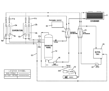

CLAIMS
1. A liquid overfeed refrigeration system comprising:
a refrigerant evaporator,
a refrigerant compressor,
a refrigerant condenser,
an expansion device, and
a refrigerant pre-heater situated before an inlet of the refrigerant
evaporator,
a sensor located downstream of the refrigerant evaporator to measure a
temperature,
pressure and/or liquid vapor ratio of a refrigerant leaving the refrigerant
evaporator, and
a control system to control an amount of heat that is applied to refrigerant
flowing
through said refrigerant pre-heater to said refrigerant evaporator based on
data received from said sensor, said control system and said refrigerant pre-
heater for heating liquid refrigerant before said liquid refrigerant enters
the
evaporator to a temperature that is 10% to 80% of the difference between an
operating temperature of the evaporator and an operating temperature of the
condenser.
2. A refrigeration system according to claim 1, wherein said refrigerant pre-
heater is a heat
exchanger.
3. A refrigeration system according to claim 2, wherein a heat source for said
pre-heater
heat exchanger is warm refrigerant liquid from said refrigerant condenser.
4. A refrigeration system according to claim 1, further comprising a separator
element for
separating liquid and vapor refrigerant leaving said evaporator.
6
WSLEGAL \ 055532 \ 00033 \ 31386639v1
Date Recue/Date Received 2022-05-24

5. A refrigeration system according to claim 1, further comprising an
evaporator feed pump
located upstream of the evaporator.
6. A refrigeration system according to claim 1, further comprising a defrost
system.
7. A refrigeration system according to claim 1, wherein said evaporator, said
compressor,
said condenser, said expansion device and said pre-heater are connected in a
refrigerant flow
path in the following order: 1) compressor ¨ 2) condenser ¨ 3) pre-heater ¨ 4)
expansion
device - 5) evaporator ¨ 1) compressor.
8. A refrigeration system comprising:
a refrigerant evaporator having an inlet and an outlet,
a liquid/vapor separator having an inlet, a vapor outlet and a liquid outlet;
a refrigerant compressor having an inlet and an outlet;
a refrigerant condenser having an inlet and an outlet,
an expansion device having an inlet and an outlet, and
a refrigerant pre-heater, having an inlet and an outlet situated before the
inlet of the
refrigerant evaporator;
a sensor located downstream of the refrigerant evaporator to measure a
temperature,
pressure and/or liquid vapor ratio of refrigerant leaving the refrigerant
evaporator,
and
a control system to control an amount of heat that is applied to a refrigerant
flowing
through said refrigerant pre-heater to said refrigerant evaporator based on
data
received from said sensor
wherein said evaporator, said sensor, said separator, said compressor, said
condenser, said preheater, and said expansion device are connected in one or
more
refrigerant flow paths via refrigerant line.
7
Date Recue/Date Received 2022-05-24

9. A refrigeration system according to claim 8, wherein said system is a
liquid overfeed
system.
10. A method for reducing a refrigerant charge of a refrigeration system
evaporator, the
method comprising the steps of: preheating liquid refrigerant prior to
introduction of the
liquid refrigerant to an inlet of said evaporator and measuring a property of
refrigerant at an
inlet of said evaporator and adjusting an amount of said preheating based on
said measured
property.
11. A method according to claim 10, comprising pre-heating the refrigerant
prior to
introduction of the refrigerant to the evaporator inlet to reduce the
refrigerant charge per ton
of refrigeration capacity by 10% or greater.
12. A method according to claim 11, comprising said pre-heating the
refrigerant prior to
introduction of the refrigerant to the evaporator inlet to reduce the
refrigerant charge per ton
of refrigeration capacity by 30% or greater.
13. A method according to claim 10, comprising heating said liquid refrigerant
to convert
10% to 30% of said liquid refrigerant to refrigerant vapor.
8
Date Recue/Date Received 2022-05-24

Description

Note: Descriptions are shown in the official language in which they were submitted.


CA 02952828 2016-12-16
WO 2016/004257
PCT/US2015/038911
EVAPORATOR LIQUID PREHEATER FOR REDUCING REFRIGERANT
CHARGE
BACKGROUND OF THE INVENTION
Field of the Invention
[0001] The present invention relates to refrigeration systems employing a
compressor,
condenser and evaporator and more particularly to such systems employing a
volatile
refrigerant circulated by the compressor; and still more particularly to such
systems of the so-
called liquid overfeed type of refrigeration system, but the invention may
also be used with a
direct expansion refrigeration system.
Background of the Invention
[0002] The vapor-compression uses a circulating liquid refrigerant as the
medium which
absorbs and removes heat from the space to be cooled and subsequently rejects
that heat
elsewhere. All such systems have a compressor, a condenser, an expansion valve
(also called
a throttle valve or metering device), and an evaporator. Circulating
refrigerant enters the
compressor in the thermodynamic state known as a saturated vapor and is
compressed to a
higher pressure, resulting in a higher temperature as well. The hot,
compressed vapor is then
in the thermodynamic state known as a superheated vapor, and it is at a
temperature and
pressure at which it can be condensed with either cooling water or cooling
air. That hot vapor
is routed through a condenser where it is cooled and condensed into a liquid
by flowing
through a coil or tubes with cool water or cool air flowing across the coil or
tubes. This is
where the circulating refrigerant rejects heat from the system and the
rejected heat is carried
away by either the water or the air (whichever may be the case).
[0003] The condensed liquid refrigerant, in the thermodynamic state known as a
saturated
liquid, is next routed through an expansion valve where it undergoes an abrupt
reduction in
pressure. That pressure reduction results in the adiabatic flash evaporation
of a part of the
1

CA 02952828 2016-12-16
WO 2016/004257
PCT/US2015/038911
liquid refrigerant. The auto-refrigeration effect of the adiabatic flash
evaporation lowers the
temperature of the liquid and vapor refrigerant mixture to where it is colder
than the
temperature of the enclosed space to be refrigerated.
[0004] The cold mixture is then routed through the coil or tubes in the
evaporator. A fan
circulates the warm air in the enclosed space across the coil or tubes
carrying the cold
refrigerant liquid and vapor mixture. That warm air evaporates the liquid part
of the cold
refrigerant mixture. At the same time, the circulating air is cooled and thus
lowers the
temperature of the enclosed space to the desired temperature. The evaporator
is where the
circulating refrigerant absorbs and removes heat which is subsequently
rejected in the
condenser and transferred elsewhere by the water or air used in the condenser.
To complete
the refrigeration cycle, the refrigerant vapor from the evaporator is again a
saturated vapor
and is routed back into the compressor.
SUMMARY OF THE INVENTION
[0005] The invention is a system and method for reducing the refrigerant
charge in a
refrigeration system, specifically by reducing the required refrigerant charge
in the evaporator
by preheating the liquid refrigerant before it is introduced to the evaporator
inlet. When
refrigerant liquid is introduced to the evaporator inlet, a portion of the
refrigerant liquid
vaporizes. This refrigerant vapor displaces refrigerant liquid at the inlet of
the evaporator. As
more refrigerant vapor is introduced, the amount of liquid inside the
evaporator is reduced.
According to the present invention, a heat exchanger placed before the liquid
refrigerant inlet
of the evaporator. This heat exchanger is used to pre-heat the liquid to
generate more vapor
when the refrigerant enters the evaporator. The increased amount of vapor
entering the
evaporator (relative to prior art systems), displaces the liquid refrigerant,
thus reducing the
refrigerant charge required for the evaporator, and thus, for the overall
system. According to
one embodiment, the liquid refrigerant may be heated in order to fully
vaporize 5%-30% of
2

CA 02952828 2016-12-16
WO 2016/004257
PCT/US2015/038911
the refrigerant. According to related embodiments, the liquid refrigerant may
be heated in
order to full vaporize 10%-30% of the refrigerant, 15%-30% of the refrigerant,
20%-30% of
the refrigerant, 5%-10% of the refrigerant, 5%-15% of the refrigerant, or 10%-
20% of the
refrigerant.
[0006] According to another embodiment, the liquid refrigerant may be heated
to a
temperature that is between 10% and 80% of the difference between the
operating
temperatures of the condenser and the evaporator. For example, if the
condenser is operating
at 90 F and the evaporator is operating at 30 F, the temperature difference
is 60 F, and the
liquid refrigerant may be warmed to 36 F (10% of the temperature difference)
or to 78 F
(80% of the difference, or anywhere in between 36 F and 78 F. According to
related
embodiments, the liquid refrigerant may be heated to a temperature that is
20%, 30%, 40%,
50%, 60% or 70% of the difference between the operating temperature of the
condenser and
the evaporator.
[0007] The heat exchanger heat source can be an external energy input such as
waste heat
produced by a refrigeration compressor, or an internal heat source such as the
warm
refrigerant liquid that exits from the condenser in the refrigeration system.
By using warm
liquid from the condenser, the net energy required to produce cooling is not
increased. This
arrangement is preferred when the liquid refrigerant flow to the evaporator is
of the liquid
overfeed type where a portion of the introduced refrigerant liquid exits the
evaporator in a
liquid state.
[0008] Any type of heat exchanger that can increase the temperature of a
refrigerant liquid
can be used. A liquid to liquid heat exchanger is preferred especially for a
liquid overfeed
evaporator. Fusion bonded plate heat exchangers such as manufactured by Alfa
Laval are
especially suited for this purpose.
3

CA 02952828 2016-12-16
WO 2016/004257
PCT/US2015/038911
BRIEF DESCRIPTION OF THE DRAWINGS
[0009] Figure 1 is a schematic of a refrigeration system according to an
embodiment of the
invention.
DETAILED DESCRIPTION
[0010] Figure 1 shows a piping schematic showing an evaporator heat exchanger
according
to an embodiment of the invention in relation to other components in a liquid
overfeed
system. This is a preferred piping arrangement to maximize refrigeration
system efficiency.
The system includes evaporators 2a and 2b, including evaporator coils 4a and
4b,
respectively, and defrost/glycol coils 6a and 6b, respectively, condenser 8,
compressor 10,
expansion devices ha and 11b (which may be valves, metering orifices or other
expansion
devices), and separator vessel 12. The foregoing elements may be connected
using standard
refrigerant tubing in the manner shown in Figure 1, or according to any
standard
arrangement. Defrost system 18 includes glycol tank 20, glycol pump 22, glycol
heat
exchanger 24 and glycol coils 6a and 6b, also connected to one-another and the
other element
of the system using refrigerant tubing according to the arrangement shown in
Figure 1, or
according to any standard arrangement. According to the invention, evaporator
pre-heater
heat exchanger 14 is located before (upstream of) the inlet to the evaporators
2a and 2b to
preheat the liquid refrigerant prior to introduction to the evaporator inlet.
The energy
required to preheat the liquid refrigerant may be provided by a source
internal to the system,
such as heated refrigerant leaving the condenser 8, as shown in Figure 1. An
evaporator feed
pump 16 may also be provided to provide the additional energy necessary to
force the
refrigerant through the evaporator heat exchanger. According to one
embodiment, the
evaporator feed pump may be selected and configured to increase the pressure
of the liquid
refrigerant to 100 psi or greater in order to prevent an excess amount of
refrigerant from
vaporizing upon pre-heating.
4

[0011] By increasing the temperature of the liquid refrigerant at the
evaporator inlet, more
vapor is produced asthe refrigerant enters the evaporator, thus reducing the
required
refrigerant charge per ton of refrigeration capacity. According to preferred
embodiments, pre-
heating the refrigerant prior to introduction of the refrigerant to the
evaporator inlet will
reduce the refrigerant charge per ton of refrigeration capacity by 10% and as
much as 50%,
relative to an identical system that does not include a refrigerant pre-
heater. Other
embodiments can reduce the refrigerant charge per ton of refrigeration
capacity by 20%, by
30%, or by 40%.
[0012] Sensors 26a and 26b may be located downstream of said evaporators 2a
and 2b,
upstream of the inlet to the separator 12, to measure the temperature,
pressure, and/or
vapor/liquid ratio of refrigerant leaving the evaporators. According to
alternative
embodiments, sensor 26c may be located in the refrigerant line between the
outlet of the
separator 12 and the inlet to the compressor 10. Sensors 26a, 26b and 26c may
be
capacitance sensors of the type disclosed in U.S. Serial Nos. 14/221,694 and
14/705,781.
According to an embodiment of the invention, the evaporator pre-heater 14 may
be
controlled by a control system 28 that can be used to manually or
automatically control the
mount of pre-heat that is provided to the refrigerant flowing through the pre-
heater.
According to a preferred embodiment, control system 28 may be configured to
control the
amount of pre-heat applied to the refrigerant passing to the evaporator based
on data,
including refrigerant temperature, pressure and/or liquid/vapor ratio,
received from said
sensors 26a, 26b, and/or 26c.
Date Recue/Date Received 2021-10-05

Representative Drawing
A single figure which represents the drawing illustrating the invention.
Administrative Status

For a clearer understanding of the status of the application/patent presented on this page, the site Disclaimer , as well as the definitions for Patent , Administrative Status , Maintenance Fee  and Payment History  should be consulted.

Administrative Status

Title Date
Forecasted Issue Date 2023-05-16
(86) PCT Filing Date 2015-07-01
(87) PCT Publication Date 2016-01-07
(85) National Entry 2016-12-16
Examination Requested 2020-06-02
(45) Issued 2023-05-16

Abandonment History

There is no abandonment history.

Maintenance Fee

Last Payment of $210.51 was received on 2023-06-23


 Upcoming maintenance fee amounts

Description Date Amount
Next Payment if small entity fee 2024-07-02 $100.00
Next Payment if standard fee 2024-07-02 $277.00

Note : If the full payment has not been received on or before the date indicated, a further fee may be required which may be one of the following

  • the reinstatement fee;
  • the late payment fee; or
  • additional fee to reverse deemed expiry.

Patent fees are adjusted on the 1st of January every year. The amounts above are the current amounts if received by December 31 of the current year.
Please refer to the CIPO Patent Fees web page to see all current fee amounts.

Payment History

Fee Type Anniversary Year Due Date Amount Paid Paid Date
Application Fee $400.00 2016-12-16
Maintenance Fee - Application - New Act 2 2017-07-04 $100.00 2017-06-26
Maintenance Fee - Application - New Act 3 2018-07-03 $100.00 2018-06-25
Maintenance Fee - Application - New Act 4 2019-07-02 $100.00 2019-06-26
Request for Examination 2020-07-06 $800.00 2020-06-02
Maintenance Fee - Application - New Act 5 2020-07-02 $200.00 2020-06-26
Maintenance Fee - Application - New Act 6 2021-07-02 $204.00 2021-06-25
Maintenance Fee - Application - New Act 7 2022-07-04 $203.59 2022-06-24
Final Fee $306.00 2023-03-16
Maintenance Fee - Patent - New Act 8 2023-07-04 $210.51 2023-06-23
Owners on Record

Note: Records showing the ownership history in alphabetical order.

Current Owners on Record
EVAPCO, INC.
Past Owners on Record
None
Past Owners that do not appear in the "Owners on Record" listing will appear in other documentation within the application.
Documents

To view selected files, please enter reCAPTCHA code :


To view images, click a link in the Document Description column. To download the documents, select one or more checkboxes in the first column and then click the "Download Selected in PDF format (Zip Archive)" or the "Download Selected as Single PDF" button.

List of published and non-published patent-specific documents on the CPD .

If you have any difficulty accessing content, you can call the Client Service Centre at 1-866-997-1936 or send them an e-mail at CIPO Client Service Centre.


Document
Description 
Date
(yyyy-mm-dd) 
Number of pages   Size of Image (KB) 
Request for Examination 2020-06-02 3 64
Change to the Method of Correspondence 2020-06-02 3 64
Examiner Requisition 2021-07-05 5 293
Amendment 2021-10-05 22 793
Electronic Grant Certificate 2023-05-16 1 2,527
Description 2021-10-05 5 209
Claims 2021-10-05 3 83
Examiner Requisition 2022-01-24 4 168
Amendment 2022-05-24 11 324
Claims 2022-05-24 3 94
Final Fee 2023-03-16 3 82
Representative Drawing 2023-04-17 1 10
Cover Page 2023-04-17 1 44
Abstract 2016-12-16 1 59
Claims 2016-12-16 3 69
Drawings 2016-12-16 1 20
Description 2016-12-16 5 211
Representative Drawing 2016-12-16 1 16
Cover Page 2017-01-11 2 44
International Search Report 2016-12-16 1 52
National Entry Request 2016-12-16 5 140