Note: Descriptions are shown in the official language in which they were submitted.
CA 02952929 2016-12-19
WO 2016/018426 PCT/US2014/049359
ESTIMATING WELL PRODUCTION PERFORMANCE
IN FRACTURED RESERVOIR SYSTEMS
CROSS-REFERENCE TO RELATED APPLICATIONS
[0001] This application and PCT/US2013/045958, which is incorporated by
reference,
are commonly assigned to Landmark Graphics Corporation.
STATEMENT REGARDING FEDERALLY SPONSORED RESEARCH
[0002] Not applicable.
FIELD OF THE DISCLOSURE
[0003] The present disclosure generally relates to systems and methods for
estimating
well production performance in fractured reservoir systems. More particularly,
the present
disclosure relates to estimating well production performance in fractured
reservoir systems using
real-time down-hole temperature and stress information from advanced
monitoring techniques.
BACKGROUND
[0004] Well production performance is commonly estimated using well known
steady
state techniques and a well model based on a nodal analysis that often needs
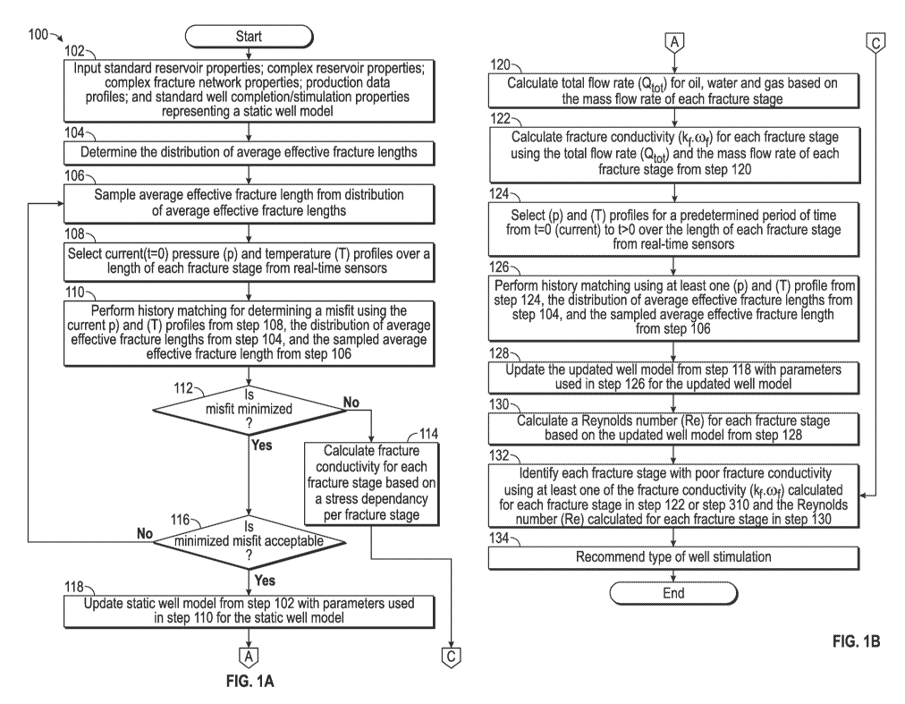
to be calibrated
using a transient build up test , a draw-down test and/or a production logging
test. In this manner,
real-time pressure could be used to try and match the pressure in the well
model. This approach
is broadly accepted, has been used for many years and works well for
reservoirs/wells that
produce without requiring stimulation techniques such as fracturing and
acidizing. In the last 10
years, reservoirs with a permeability of less than 1 md have generated much
interest due to an
abundance of hydrocarbons deposited in tight rocks. However, these resources
need the
1
CA 02952929 2016-12-19
WO 2016/018426 PCT/US2014/049359
assistance of multiple hydraulic fracture stages to be economically produced
and often require
more than two fracture stages per well. In a tight reservoir system, the wells
are drilled with
extensive lateral sections often that operators can fracture. Conventional
estimation of well
production performance thus, may be undesirable due to the fact that a well
requires stimulation
techniques and because real-time pressure is the only parameter used to test
the well model.
Moreover, the challenge with wells that require stimulation techniques is to
estimate the
production performance of each individual fracture at any particular time
(e.g. real-time, right
time, on-demand, daily, weekly).
BRIEF DESCRIPTION OF THE DRAWINGS
[0005] The present disclosure is described below with references to the
accompanying
drawings in which like elements are referenced with like reference numerals,
and in which:
[0006] FIGS. 1A-1B is a flow diagram illustrating one embodiment of a method
for
implementing the present disclosure.
[0007] FIG. 2 is a flow diagram illustrating one embodiment of a method for
performing
step 104 in FIG. 1.
[0008] FIG. 3 is a flow diagram illustrating one embodiment of a method for
performing
step 114 in FIG. 1.
[0009] FIG. 4A is a display illustrating a collection of micro-seismic imaging
events
associated with a fracture cluster.
[0010] FIG. 4B is a display illustrating 3D fracture planes based on a time
correlation of
the micro-seismic imaging events in FIG. 4A.
2
CA 02952929 2016-12-19
WO 2016/018426 PCT/US2014/049359
[0011] FIG. 5A is a simple schematic model of an induced fracture system
illustrating
bi-wing fractures with the same (xeff), the same (SRV) and only one fracture
per stage.
[0012] FIG. 5B is a complex schematic model of an induced fracture system
illustrating
multiple-complex fracture networks each with different (xeff), different (SRV)
and multiple
fractures per stage.
[0013] FIG. 6 is a diagram illustrating exemplary results for the water and
oil flow
contributions for each fracture stage at a steady state condition calculated
in step 120.
[0014] FIG. 7 is a diagram illustrating exemplary fracture stages and their
fracture
conductivity.
[0015] FIG. 8 is a diagram illustrating an exemplary comparison of an acoustic
amplitude and acoustic spectrogram with a sound speed plot.
[0016] FIG. 9 is a block diagram illustrating one embodiment of a computer
system for
implementing the present disclosure.
DETAILED DESCRIPTION OF THE PREFERRED EMBODIMENTS
[0017] The present disclosure overcomes one or more deficiencies in the prior
art by
providing systems and methods for estimating well production performance in
fractured
reservoir systems using real-time down-hole temperature and stress information
from advanced
monitoring techniques.
[0018] In one embodiment, the present disclosure includes a method for
identifying poor
fracture conductivity in fractured reservoir systems to use in refracturing,
which comprises: a)
sampling an average effective fracture length from a distribution of average
effective fracture
3
CA 02952929 2016-12-19
WO 2016/018426 PCT/US2014/049359
lengths; b) selecting current pressure and temperature profiles over a length
of each fracture
stage; c) performing history matching to determine a misfit using the current
pressure and
temperature profiles, the distribution of average effective fracture lengths,
the sampled average
effective fracture length and a computer processor; d) updating a static well
model using the
current pressure and temperature profiles, the distribution of average
effective fracture lengths
and the sampled average effective fracture length for the static well model;
e) calculating a
fracture conductivity for each fracture stage; f) selecting pressure and
temperature profiles for a
predetermined period of time over the length of each fracture stage; g)
performing history
matching using at least one pressure and temperature profile from the pressure
and temperature
profiles selected for the predetermined period of time, the distribution of
any effective fracture
lengths, the sampled average effective fracture length and the computer
processor; h) updating
the updated static well model, which represents a new updated static well
model, using the at
least one pressure and temperature profile from the pressure and temperature
profiles, selected
for the predetermined period of time, the distribution of average effective
fracture lengths and
the sampled average effective fracture length for the updated static well
model; i) calculating a
Reynolds number for each fracture stage based on the new updated static well
model; and j)
identifying the fracture and each fracture stage to determine poor fracture
conductivity using at
least one of the fracture conductivity and the Reynolds number calculated for
each fracture stage.
[0019] In another embodiment, the present disclosure includes a non-transitory
program
carrier device tangibly carrying computer-executable instructions for
identifying poor fracture
conductivity in fractured reservoir systems to use in refracturing, the
instructions being
4
CA 02952929 2016-12-19
WO 2016/018426 PCT/US2014/049359
executable to implement: a) sampling an average effective fracture length from
a distribution of
average effective fracture lengths; b) selecting current pressure and
temperature profiles over a
length of each fracture stage; c) performing history matching to determine a
misfit using the
current pressure and temperature profiles, the distribution of average
effective fracture lengths,
the sampled average effective fracture length; d) updating a static well model
using the current
pressure and temperature profiles, the distribution of average effective
fracture lengths and the
sampled average effective fracture length for the static well model; e)
calculating a fracture
conductivity for each fracture stage; f) selecting pressure and temperature
profiles for a
predetermined period of time over the length of each fracture stage; g)
performing history
matching using at least one pressure and temperature profile from the pressure
and temperature
profiles selected for the predetermined period of time, the distribution of
any effective fracture
lengths, the sampled average effective fracture length; h) updating the
updated static well model,
which represents a new updated static well model, using the at least one
pressure and
temperature profile from the pressure and temperature profiles, selected for
the predetermined
period of time, the distribution of average effective fracture lengths and the
sampled average
effective fracture length for the updated static well model; i) calculating a
Reynolds number for
each fracture stage based on the new updated static well model; and j)
identifying the fracture
and each fracture stage to determine poor fracture conductivity using at least
one of the fracture
conductivity and the Reynolds number calculated for each fracture stage.
[0020] In yet another embodiment, the present disclosure includes a method for
identifying poor fracture conductivity in fractured reservoir systems to use
in refracturing, which
CA 02952929 2016-12-19
WO 2016/018426 PCT/US2014/049359
comprises: a) selecting acoustic profiles for a predetermined period of time
over a length of each
fracture stage; b) calculating a compressional velocity using at least one of
the acoustic profiles;
c) identifying a main lithology of an acoustic medium represented by the
acoustic profiles and a
related Gardner coefficient; d) calculating an effective stress using the
compressional velocity
and the Gardner coefficient; e) calculating a fracture conductivity for each
fracture stage using
the effective stress and a computer processor; and f) identifying each
fracture stage with poor
fracture conductivity.
[0021] In yet another embodiment, the present disclosure includes a non-
transitory
program carrier device tangibly carrying computer-executable instructions for
identifying poor
fracture conductivity in fractured reservoir systems to use in refracturing,
which comprises: a)
selecting acoustic profiles for a predetermined period of time over a length
of each fracture
stage; b) calculating a compressional velocity using at least one of the
acoustic profiles; c)
identifying a main lithology of an acoustic medium represented by the acoustic
profiles and a
related Gardner coefficient; d) calculating an effective stress using the
compressional velocity
and the Gardner coefficient; e) calculating a fracture conductivity for each
fracture stage using
the effective stress; and f) identifying each fracture stage with poor
fracture conductivity.
[0022] The subject matter of the present disclosure is described with
specificity,
however, the description itself is not intended to limit the scope of the
disclosure. The subject
matter thus, might also be embodied in other ways, to include different steps
or combinations of
steps similar to the ones described herein, in conjunction with other present
or future
technologies. Moreover, although the term "step" may be used herein to
describe different
6
CA 02952929 2016-12-19
WO 2016/018426 PCT/US2014/049359
elements of methods employed, the term should not be interpreted as implying
any particular
order among or between various steps herein disclosed unless otherwise
expressly limited by the
description to a particular order. While the present disclosure may be applied
in the oil and gas
industry, it is not limited thereto and may also be applied in other
industries to achieve similar
results.
7
CA 02952929 2016-12-19
WO 2016/018426 PCT/US2014/049359
Method Description
[0023] Referring now to FIGS. 1A-1B, a flow diagram illustrates one embodiment
of a
method 100 for implementing the present disclosure. The method 100 evaluates
the production
performance given for each individual fracture in a reservoir system along the
well completion in
terms of oil, water and gas production. Micro-seismic information is used to
setup the initial
fracture geometry and cluster per fracturing stage. The method 100 uses real-
time information
from fiber optics such as distributed temperature sensors (DTS) and down-hole
pressure gauges
to estimate the production performance of each fracture stage compared to the
network of
fractures. The method 100 also uses real-time information from fiber optics
such as distributed
acoustic sensors (DAS) and DTS to estimate the geo-mechanical parameters that
affect the
fracture geometry and thus, productivity, due to reservoir pressure depletion
and bottom-hole
pressure during production.
[0024] In step 102, standard reservoir properties (e.g. formation thickness,
bottom hole
pressure (BHP), matrix porosity and permeability, rock types), complex
reservoir properties (e.g.
petrophysical properties (e.g. hydrocarbon content, clay content)) from
advanced petrophysical
well-log interpretation using mapped properties (e.g. Total Organic Carbon,
porosity and
brittleness) spatially distributed over the reservoir and constrained with
well data), complex
fracture network ("CFN") properties (e.g. data corresponding to clusters in a
CFN model),
production data profiles (e.g. gas/oil/water rates and BHP), and standard well
completion and
stimulation properties (e.g. well trajectory, well log pressure (p) and
temperature (T) profiles, RP
curves, PVT fractured intervals, micro-seismic data, number of fractured
stages, initial
8
CA 02952929 2016-12-19
WO 2016/018426 PCT/US2014/049359
distribution of average effective fracture lengths, sampled average effective
fracture length and
the initial fracture conductivity per stage) hereinafter referred to as a
static well model are input
into a single well reservoir simulator using the client interface and/or the
video interface
described further in reference to FIG. 9. Clusters provide a much more
accurate representation
of the fracture system because fracking produces not only an elongated hi-wing
fracture but
rather, a network of smaller complex fractures that are preferably all
interconnected and
communicate between each other that form a CFN. Each CFN is impacted by other
rock
properties such as, for example, the standard reservoir properties and the
mapped properties
mentioned hereinabove.
[0025] In step 104, the distribution of average effective fracture lengths is
determined.
One embodiment of a method for performing this step is described further in
reference to FIG. 3.
[0026] In step 106, the average effective fracture length is sampled from the
distribution
of average effective fracture lengths (discrete or continuous) determined in
step 104. Any well-
known standard probabilistic sampling technique (e.g. random sampler) may be
used for
sampling. In this manner, uncertainty maps of estimated improved permeability
(kimp) can be
generated with lower median and higher probability scenarios (e.g. P10, P50
and P90 models).
[0027] In step 108, current (t=0) pressure (p) and temperature (T) profiles
over a length
of each fracture stage are selected from real-time sensors using the client
interface and/or the
video interface described further in reference to FIG. 9.
[0028] In step 110, history matching is performed for determining a misfit by
repeatedly
running a simulation, which is referred to as a dynamic well model, using the
current (p) and (T)
9
CA 02952929 2016-12-19
WO 2016/018426 PCT/US2014/049359
profiles from step 108, the distribution of average effective fracture lengths
from step 104, the
sampled average effective fracture length from step 106 and techniques well-
known in the art for
comparing these parameters to the same parameters for the well model from step
102. The
history matching result represents a misfit, as a percentage deviation,
between the current (p) and
(T) profiles from step 108 and the (p) and (T) profiles from the well model in
step 102.
[0029] In step 112, the method 100 determines if the misfit from step 110 is
minimized
compared to the misfit determined in the last iteration of step 110. The first
iteration of step 110
(i.e. the first determined misfit) cannot be compared to another misfit and
thus, represents a
minimized misfit. If the misfit is minimized, then the method 100 proceeds to
step 116. If the
misfit is not minimized, then the method 100 proceeds to step 114.
[0030] In step 114, the fracture conductivity for each fracture stage is
calculated based on
a stress dependency per fracture stage. One embodiment of a method for
performing this step is
described further in reference to FIG. 3
[0031] In step 116, the method 100 determines if the minimized misfit from
step 110 is
acceptable. Acceptable is preferably 10% deviation or less, however, may be
some other
predetermined deviation. If the minimized misfit is not acceptable, then the
method 100 returns
to step 106. If the minimized misfit is acceptable, then the method 100
proceeds to step 118.
[0032] In step 118, the static well model from step 102 is updated with the
parameters
used in step 110 for the static well model using techniques well known in the
art.
[0033] In step 120, a total flow rate (Qt0t) is calculated for oil, water and
gas, based on
the mass flow rate of each fracture stage, using techniques well known in the
art. The transient
CA 02952929 2016-12-19
WO 2016/018426 PCT/US2014/049359
distribution of water, gas or oil in the stimulated volume is represented by
equation 1 and
equation 2 represents the flow of each under the Darcy law:
aco paS, a
(1)
at i=i
1 ( op,
(2)
X
= ____________________ ka ___ )(Jag,
Icx\a
Xi = X; x2 =z
(X, Z) E : pa -= pai (X)
(X, Z) pa = pa'
where (0 is the formation porosity; gi are the components of the gravity
vector; it is the flow
velocity, index a refers to the properties of the a-th phase; pa is the
pressure; pa is the density; Sa
is the fluid saturation; ka is the permeability; pa is the viscosity; pal (x)
is the pressure in the
fracture F1 at coordinate x; and p: is the fixed phase pressure at the domain
boundary 12. For
liquid-gas multiphase flow compressibility, densities and viscosities may be
taken from any
well-known PVT table and the remaining variables are taken from the static
well model. After
finding the distribution of pressure in the computation domain, the fluid mass
flux rate density Ji
to the i-th individual fracture can be determined for each fracture stage
using equation 3:
kfPf Op
J ¨ ¨ ¨ (3)
A / f az j Oz _
These fluxes will be used to calculate the distribution of flow pressure pf
inside individual
fractures according to equation 4:
11
CA 02952929 2016-12-19
WO 2016/018426 PCT/US2014/049359
(
pfhkp
__________________________ = (X)
ax
\ f aX
(4)
where pf and 1ti1. are the density and viscosity of the mixture, respectively;
k p is the fracture
permeability and h is pay or layer thickness in ft. from the static well
model. Fluid density and
viscosity are taken from any well-known PVT table and fracture permeability is
taken from
fracture treatment already setup in the static well model. Fluid velocity is
taken from the output
of the dynamic well model. Under Darcy law, fracture productivity can be
calculated using
equation 5:
(x)* P f)
(5)
where: Qx is the mass flow rate for the fracture stage x; J(x) is the mass
flux from equation 4; Pe
is the reservoir pressure in psi from current pressure data in the dynamic
well model; and pf is
flowing bottom-hole pressure in psi from current pressure data in the dynamic
well model. The
total flow rate (Qtet) for oil, water and gas may be calculated using equation
6:
Qtot= Qxt Qx 2+ Qx 3 + Qx n-Fi for oil, water and gas
(6)
where Qx,, is the mass flow rate of each fracture stage and the contribution
ratio per fracture stage
is Qxn/Qtot. In FIG. 6, the diagram illustrates exemplary results for the
water, oil and gas flow
contribution ratios (0 /
as a percentage for six (6) different fracture stages at a steady state
, 0tot,1 ,
condition.
[0034] In step 122, fracture conductivity (kf.wf) is calculated for each
fracture stage
12
CA 02952929 2016-12-19
WO 2016/018426 PCT/US2014/049359
using the total flow rate (Qt0t) for oil, water and gas from step 120, the
mass flow rate of each
fracture stage (Qõ) from step 120 and techniques well known in the art.
Assuming bilinear flow
into the fracture and no flow between the reservoir and exposure zone with
wellbore (only
fractures), a rectangular fracture of constant width, the production may be
obtained using
equation 7:
Qx/(Pe-pf)= 0.00113*kf*c)phf/(Bo*I.1õ*(Xf+Sf)
(7)
where kf is proppant fracture conductivity at closure stress during the
treatment in md. from the
static well model; (of is fracture width from fracture design or well test, if
available, in ft from the
static well model; Xf is half fracture length in ft from micro seismic in the
static well model; hf is
fracture height from micro seismic in ft. from the static well model; Sf is
skin generated by
fracture (dimensionless) from the static well model; Bo is fluid formation
volume factor from
any well-known PVT table; uo is fluid viscosity in cP from any well-known PVT
table; Pe is the
reservoir pressure in psi from current pressure data in the dynamic well
model; and pf is flowing
bottom-hole pressure in psi from current pressure data in the dynamic well
model. Therefore
fracture conductivity (kf.cof) can be calculated by equation 8:
kf* (of =Qx Bo* uo*(Xf+Sf)/ {0.00113* *hf (Pe-POI (8)
[0035] In step 124, (p) and (T) profiles for a predetermined period of time
from -1=0
(current) to t>0 over the length of each fracture stage are selected from real-
time sensors using
the client interface and/or the video interface described further in reference
to FIG. 9.
13
CA 02952929 2016-12-19
WO 2016/018426 PCT/US2014/049359
[0036] In step 126, history matching is performed by running a simulation
using at least
one (p) and (T) profile from step 124, the distribution of average effective
fracture lengths from
step 104, the sampled average effective fracture length from step 106 and
techniques well-known
in the art for comparing these parameters to the same parameters for the
updated well model
from step 118. A separate simulation may be run for each (p) and (T) profile
from step 124.
[0037] In step 128, the updated well model from step 118 is updated with the
parameters
used in step 126 for the updated well model using techniques well known in the
art.
[0038] In step 130, a Reynolds number (Re) is calculated for each fracture
stage based on
the updated well model from step 128 using equation 9:
Re =1/2 t1a*pf/{1.4*Rpsd* (1 - 0)}
(9)
where U, is the flow velocity from the updated dynamic well model in step 118
based on
equation 2; pf is fluid density; Rpsd is the pore radius of fracture proppant;
(I) is porosity of
fracture proppant; and [if is fluid viscosity in cP. The variables pf, 14,
Rpsd, and ,31) are given by the
static well model from step 102.
[0039] In step 132, each fracture stage with poor fracture conductivity is
identified using
at least one of the fracture conductivity (kf.o)f) calculated for each
fracture stage in step 122 or
step 310 and the Reynolds number (Re) calculated for each fracture stage in
step 130. Poor
fracture conductivity may be associated with a fracture conductivity that is
less than 1 md.ft.
and/or a Reynolds number greater than 1. In FIG. 7, a diagram illustrates
exemplary fracture
stages and their fracture conductivity as a result of step 132. The velocity
(i/a) as a result of
equation 2, static reservoir temperature from the well model in step 102, the
fracture conductivity
14
CA 02952929 2016-12-19
WO 2016/018426 PCT/US2014/049359
(kf.aif) calculated in step 122 and the Reynolds number (Re) calculated in
step 130 may be
correlated with the following fracture patterns in FIG. 7:
Pattern 1 (fracture open and propped): a fracture is open and very well
propped when tra is high, temperature is cool, kf.wf is greater than 1 md.ft.
and Re
is less than 1.0 (laminar flow);
Pattern 2 (fracture open and non-propped): a fracture is open and not well
propped when ita is high, temperature is high, kf.of is less than 1 md.ft. and
Re is
near 1.0 (transitional flow);
Pattern 3 (fracture almost closed): a fracture is almost closed when uf, is
high, temperature is very high, kf.o.if is less than or equal to 1 md.ft. and
Re is
greater than 1.0 (turbulent flow);
Pattern 4 (fracture choked): a fracture is choked when tra is low,
temperature is very high, kf.(of is less than or equal to 1 md.ft. and Re is
less than
1; and
Pattern 5 (fracture closed or simple small fissure): a fracture is closed or
is
a simple small fissure (micro-fracture) when ita is low, temperature is very
high,
kf.eif is less than or equal to 1 md.ft. and Re is less than 1.
[0040] In step 134, various types of well stimulation may be recommended using
the
client interface and/or the video interface described further in reference to
FIG. 9 based on the
fracture stages identified in step 132 with poor fracture conductivity such
as, for example, re-
fracturing, fracture re-orientation, and redesign perforation.
CA 02952929 2016-12-19
WO 2016/018426 PCT/US2014/049359
[0041] Referring now to FIG. 2, a flow diagram of one embodiment of a method
200 for
performing step 104 in FIG. 1 is illustrated.
[0042] In step 201, a well (w) is automatically selected from a total number
of wells (W)
input in step 102 or, alternatively, may be selected using the client
interface and/or the video
interface described further in reference to FIG. 9.
[0043] In step 202, a fracturing stage (s) is automatically selected from a
total number of
fracturing stages (S) per well (w) input in step 102 or, alternatively, may be
selected using the
client interface and/or the video interface described further in reference to
FIG. 9.
[0044] In step 203, a fracture plane (f) is automatically selected from a
total number of
fracture planes (F) per fracturing stage (s) input in step 102 or,
alternatively, may be selected
using the client interface and/or the video interface described further in
reference to FIG. 9. It is
assumed that the fracture planes (f) within each fracturing stage (s) are
distributed as clusters and
not the simplified single hi-wing fractures.
[0045] In step 204, the effective fracture length (xe'ffv ,,,f ) for the
selected fracture plane
(f), fracturing stage (s) and well (w) is read from the data corresponding to
the CFN model input
in step 102. The data corresponding to the CFN model may include, for example,
the number of
3D fracture planes for a cluster per fracturing stage. The 3D fracture planes
are constructed based
on a temporal analysis of micro-seismic imaging events. In FIG. 4A, a display
400a of a
collection of interpreted micro-seismic imaging events associated with a
fracture cluster is
illustrated. In FIG. 4B, a display 400b of 3D fracture planes based on a time
correlation of the
micro-seismic imaging events in FIG. 4A is illustrated. The 3D fracture planes
in the display
16
CA 02952929 2016-12-19
WO 2016/018426 PCT/US2014/049359
400b are protruded by a well trajectory to illustrate the interpreted results
of the fracking process.
Based on this data input from step 102, the dimension or length of the longest
axis of the selected
fracture plane (n, for fracturing stage (s) and well (w) may be read and
designated as the effective
fracture length of that selected fracture plane (f). In FIG. 5B, a complex
schematic model of an
induced fracture system illustrates multiple-complex fracture networks, each
with different (xeff),
different Stimulated Reservoir Volume (SRV) and multiple fractures per
fracturing stage. As
compared to the simplified model of an induced fracture system based on bi-
wing fractures
illustrated in FIG. 5A, the advantages of the more complex model in FIG. 5B
are readily
apparent in view of the much more accurate representation of the fracture
system.
[0046] In step 205, the average effective fracture length
) for fracturing stage (s) is
calculated using each effective fracture length read in step 204 and equation
10:
1
xeff,, = ¨F f
(10)
wherein (5µce'ffy ,,,f ) corresponds to the effective fracture length for
selected fracture plane (f)
within a selected fracturing stage (s).
[0047] In step 206, the method 200 determines if there is another fracture
plane (f) to
select from the total number of fracture planes (F). If there is another
fracture plane (f) to select,
then the method 200 returns to step 203 to select another fracture plane (f)
from the total number
of fracture planes (F). If there is not another fracture plane (f to select,
then the method 200
proceeds to step 207.
[0048] In step 207, the method 200 determines if there is another fracturing
stage (s) to
17
CA 02952929 2016-12-19
WO 2016/018426 PCT/US2014/049359
select from the total number of fracturing stages (S). If there is another
fracturing stage (s) to
select, then the method 200 returns to step 202 to select another fracturing
stage (s) from the total
number of fracturing stages (S). If there is not another fracturing stage (s)
to select, then the
method 200 proceeds to step 208.
[0049] In step 208, the method 200 determines if there is another well (w) to
select from
the total number of wells (W). If there is another well (w) to select, then
the method 200 returns
to step 201 to select another well (w) from the total number of wells (W). If
there is not another
well (w) to select, then the method 200 proceeds to step 209.
[0050] In step 209, a reservoir or a well-log property (p) is automatically
selected from a
total number of complex reservoir properties (P) input in step 102, or,
alternatively, may be
selected using the client interface and/or the video interface described
further in reference to FIG.
9.
[0051] In step 210, the average effective fracture length Cce'ffy ) for each
respective
fracturing stage (s) calculated in step 205 is correlated with the reservoir
or well-log property (p)
selected in step 209 to build a distribution (discrete or continuous) of the
average effective
fracture lengths (3'c'effiv ,sip ). A discrete conditional distribution
(histogram) may be built using
equation 11:
w Prob(P = pX f
Xeff,tp ¨ 1)(1), eff __________________________________________________
kifvf,s P p) (11)
Prob(P = p)
wherein "Prob" denotes "probability", (xeff) defines the overall sampling
domain of the average
18
CA 02952929 2016-12-19
WO 2016/018426 PCT/US2014/049359
effective fracture length as the dependent probabilistic variable, and (P)
defines the overall
sampling domain of the complex reservoir property as the independent
probabilistic variable.
Alternatively, a continuous conditional distribution (pdf) may be built using
equation 12:
Probr,x 0), f ,$)
,sip=PrOb(Xeff P = p) =
(12)
Probp(p)
wherein ( Probp,x,ff ,v)) defines the joint density (pdf) of (P) and
(xeff), while ( Prob p (p))
defines the marginal density for (P). For pdf normalization purposes it is
necessary to hold
Prob (p)> O.
[0052] In step 212, the method 200 determines if there is another reservoir or
well-log
property (p) to select from the total number of complex reservoir properties
(P). If there is
another reservoir or well-log property (p) to select, then the method 200
returns to step 209 to
select another reservoir or well-log property (p) from the total number of
complex reservoir
properties (P). If there is not another reservoir or well-log property (p) to
select, then the method
200 returns the distribution of average effective fracture lengths to step
106.
[0053] Referring now to FIG. 3, a flow diagram of one embodiment of a method
300 for
performing step 114 in FIG. 1 is illustrated.
[0054] In step 302, acoustic profiles for a predetermined period of time from
t=0
(current) to t>0 over the length of each fracture stage are selected from real-
time sensors using
the client interface and/or the video interface described further in reference
to FIG. 9.
[0055] In step 304, a compressional velocity (Vp) is calculated using at least
one of the
acoustic profiles from step 302 and equation 13:
19
CA 02952929 2016-12-19
WO 2016/018426 PCT/US2014/049359
Vp = frequency * wave-length 401/4,
(13)
where frequency (f) and wave length PO are taken from the acoustic profiles.
In FIG. 8, the diagram illustrates an exemplary comparison of an acoustic
amplitude and
acoustic spectrogram with a sound speed plot. The acoustic amplitude is
illustrated at every
second along a horizontal section showing high amplitude near the fracture
face, the acoustic
spectrogram illustrates frequency along the horizontal section showing a high
spectrogram at the
fracture face, and the sound speed plot illustrates the sound interference
lines.
[0056] In step 306, the main lithology (e.g. sand, shale, carbonate,
siltstone) of the
acoustic medium and related Gardner coefficient (a) are identified using the
lithology log
generated in the static model from step 102, table 1 below and the client
interface and/or the
video interface described further in reference to FIG. 9. The Gardner
coefficients are found in
the average (mean) column and are based on data from numerous wells where both
bulk density
and sonic logs were measured.
Gardner Coefficient (a) for 13=0.25
Min Max mean STD
Sands 0.19418 0.23345 0.214611 0.003689
Shale 0.22326 0.31431 0.241292 0.005644
Carbonates 0.21771 0.24775 0.230706 0.005528
Siltstone 0.23175 0.26756 0.245668 0.005792
Table 1
[0057] In step 308, an effective stress (o-eff) is calculated using the
compressional
velocity (Vp) from step 304, the Gardner coefficient (a) from step 306 and
techniques well known
in the art. Shear velocity (Vs) can be calculated using equation 14:
CA 02952929 2016-12-19
WO 2016/018426 PCT/US2014/049359
Vs = aVpi6 (14)
where the Gardner coefficient (a) and 13 are given by table 1 from step 306
and the compressional
velocity (Vp) is from step 304. Rock density (p,) can be calculated using
equation 15:
pr = avg
(15)
where p,. is rock density; Vp = compressional velocity from step 304; a =
Gardner coefficient
from step 306; and 13 is given by table 1 from step 306. Poisson's ratio (v)
can be calculated
using equation 16:
(v2 ¨ 2vn
= ____________________________________ P
(16)
2(q - vsn
where the compressional velocity (Vp) is from step 304 and the shear velocity
(Vs) is from
equation 14. Therefore, the effective stress ((Jeff) measured a time step t in
front to the fracture
face can be calculated using equation 17:
v
Cie f f (avert ¨ Pp) + Pp ¨ fBHP
(17)
where v is the Poisson ratio from equation 16; avert is overburden effect or
maximum vertical
stress from the static well model; Pp is pore pressure or reservoir pressure
(Pe) at time step t
from the static well model; and fBHP or pf is flowing BHP at time step t
measured in front to the
fracture face (annular or tubing) from the dynamic well model.
[0058] In step 310, a fracture conductivity (kf.wf) is calculated for each
fracture stage
based on a stress dependency for each fracture stage using the effective
stress ((Jeff) from step
21
CA 02952929 2016-12-19
WO 2016/018426 PCT/US2014/049359
308 and equation 18:
kb wb = kf wf e-b(6eff-creffinit)
(18)
where Geff mit is initial effective stress in front to fracture face after the
fracture treatment from
fracture treatment in the static well model; b is the coefficient permeability
modulus (values go
from 0.6-0.9) and kf or kffof are the initial (i) fracture permeability or
fracture conductivity,
respectively, after fracture treatment from the static well model. The
fracture conductivity for
each fracture stage based on a stress dependency for each fracture stage is
returned to step 132
for identification of poor fracture conductivity.
[0059] The method 100 therefore, estimates well production performance over
time in
fractured reservoir systems using real-time down-hole information. In this
manner, the method
100 can be used to identify i) the production performance of each fracture
stage; ii) the closed
fractures that need to be re-fractured; and iii) the fractures that generate
underbalance or back-
flows in the entire production profile. The method 100 can also be used to i)
generate a flow
regime profile; ii) generate recommendations to re-stimulate or re-fracture
specific zones; iii)
maximize oil sweep efficiency for each reservoir region thus, allowing a
homogeneous oil
drainage along the horizontal section of the well; and iv) evaluate reservoir
model connectivity
with fractures.
System Description
[0060] The present disclosure may be implemented through a computer-executable
program of instructions, such as program modules, generally referred to as
software applications
or application programs executed by a computer. The software may include, for
example,
22
CA 02952929 2016-12-19
WO 2016/018426 PCT/US2014/049359
routines, programs, objects, components and data structures that perform
particular tasks or
implement particular abstract data types. The software forms an interface to
allow a computer to
react according to a source of input. NEToolt,õ, which is a commercial
software application
marketed by Landmark Graphics Corporation, may be used as an interface
application to
implement the present disclosure. The software may also cooperate with other
code segments to
initiate a variety of tasks in response to data received in conjunction with
the source of the
received data. The software may be stored and/or carried on any variety of
memory such as CD-
ROM, magnetic disk, bubble memory and semiconductor memory (e.g. various types
of RAM or
ROM). Furthermore, the software and its results may be transmitted over a
variety of carrier
media such as optical fiber, metallic wire and/or through any of a variety of
networks, such as
the Internet.
[0061] Moreover, those skilled in the art will appreciate that the disclosure
may be
practiced with a variety of computer-system configurations, including hand-
held devices,
multiprocessor systems, microprocessor-based or programmable-consumer
electronics,
minicomputers, mainframe computers, and the like. Any number of computer-
systems and
computer networks are acceptable for use with the present disclosure. The
disclosure may be
practiced in distributed-computing environments where tasks are performed by
remote-
processing devices that are linked through a communications network. In a
distributed-
computing environment, program modules may be located in both local and remote
computer-
storage media including memory storage devices. The present disclosure may
therefore, be
implemented in connection with various hardware, software or a combination
thereof, in a
23
CA 02952929 2016-12-19
WO 2016/018426 PCT/US2014/049359
computer system or other processing system,
[0062] Referring now to FIG. 9, a block diagram illustrates one embodiment of
a
system for implementing the present disclosure on a computer. The system
includes a
computing unit, sometimes referred to as a computing system, which contains
memory,
application programs, a client interface, a video interface, and a processing
unit. The computing
unit is only one example of a suitable computing environment and is not
intended to suggest any
limitation as to the scope of use or functionality of the disclosure.
[0063] The memory primarily stores the application programs, which may also be
described as program modules containing computer-executable instructions,
executed by the
computing unit for implementing the present disclosure described herein and
illustrated in FIGS.
1-8. The memory therefore, includes a fracture production performance module,
which enables
steps 102-108, 112-124 and 128-132 described in reference to FIGS. 1A-1B. The
fracture
production performance module may integrate functionality from the remaining
application
programs illustrated in FIG. 9. In particular, NEToolt,õ may be used as an
interface application
to perform the remaining steps in FIGS 1A and 1B. Although NETooltm may be
used as an
interface application, other interface applications may be used, instead, or
the fracture production
performance module may be used as a stand-alone application.
[0064] Although the computing unit is shown as having a generalized memory,
the
computing unit typically includes a variety of computer readable media. By way
of example,
and not limitation, computer readable media may comprise computer storage
media and
communication media. The computing system memory may include computer storage
media in
24
CA 02952929 2016-12-19
WO 2016/018426 PCT/US2014/049359
the form of volatile and/or nonvolatile memory such as a read only memory
(ROM) and random
access memory (RAM). A basic input/output system (BIOS), containing the basic
routines that
help to transfer information between elements within the computing unit, such
as during start-up,
is typically stored in ROM. The RAM typically contains data and/or program
modules that are
immediately accessible to, and/or presently being operated on, the processing
unit. By way of
example, and not limitation, the computing unit includes an operating system,
application
programs, other program modules, and program data.
[0065] The components shown in the memory may also be included in other
removable/nonremovable, volatile/nonvolatile computer storage media or they
may be
implemented in the computing unit through an application program interface
("API") or cloud
computing, which may reside on a separate computing unit connected through a
computer
system or network. For example only, a hard disk drive may read from or write
to
nonremovable, nonvolatile magnetic media, a magnetic disk drive may read from
or write to a
removable, nonvolatile magnetic disk, and an optical disk drive may read from
or write to a
removable, nonvolatile optical disk such as a CD ROM or other optical media.
Other
removable/nonremovable, volatile/nonvolatile computer storage media that can
be used in the
exemplary operating environment may include, but are not limited to, magnetic
tape cassettes,
flash memory cards, digital versatile disks, digital video tape, solid state
RAM, solid state ROM,
and the like. The drives and their associated computer storage media discussed
above provide
storage of computer readable instructions, data structures, program modules
and other data for
the computing unit.
CA 02952929 2016-12-19
WO 2016/018426 PCT/US2014/049359
[0066] A client may enter commands and information into the computing unit
through
the client interface, which may be input devices such as a keyboard and
pointing device,
commonly referred to as a mouse, trackball or touch pad. Input devices may
include a
microphone, joystick, satellite dish, scanner, or the like. These and other
input devices are often
connected to the processing unit through the client interface that is coupled
to a system bus, but
may be connected by other interface and bus structures, such as a parallel
port or a universal
serial bus (USB).
[0067] A monitor or other type of display device may be connected to the
system bus
via an interface, such as a video interface. A graphical user interface
("GUI") may also be used
with the video interface to receive instructions from the client interface and
transmit instructions
to the processing unit. In addition to the monitor, computers may also include
other peripheral
output devices such as speakers and printer, which may be connected through an
output
peripheral interface.
[0068] Although many other internal components of the computing unit are not
shown,
those of ordinary skill in the art will appreciate that such components and
their interconnection
are well known.
[0069] While the present disclosure has been described in connection with
presently
preferred embodiments, it will be understood by those skilled in the art that
it is not intended to
limit the disclosure to those embodiments. It is therefore, contemplated that
various alternative
embodiments and modifications may be made to the disclosed embodiments without
departing
from the spirit and scope of the disclosure defined by the appended claims and
equivalents
26
CA 02952929 2016-12-19
WO 2016/018426
PCT/US2014/049359
thereof.
27