Note: Descriptions are shown in the official language in which they were submitted.
CA 02952991 2016-12-19
WO 2014/207503
PCT/1B2013/002427
BRUSRHEAD FOR SKIN BRUSH APPLIANCE
CROSS-REFERENCE TO RELATED APPLICATION
This application claims the benefit to U.S. Application Serial No. 61/838783,
filed
.5 June 24, 2013.
BACKGROUND
Power skin care brushes, such as those useful for cleansing of the facial
region,
are typically driven directly, such as by a drive shaft or shafts, gears and a
motor. The
skin brush typically includes a single brushhead, with a plurality of
bristle/filament tufts,
which move in unison. Some brushheads rotate 360 degrees in one direction
continuously, while others oscillate through a selected angle. The higher
frequency skin
brushes are often referred to as sonic or sonic frequency brushes, the
frequency range of
such brushes being about 120-300 Hz.
SUMMARY
This summary is provided to introduce a selection of concepts in a simplified
form that are further described below in the Detailed Description. This
summary is not
intended to identify key features of the claimed subject matter, nor is it
intended to be
used as an aid in determining the scope of the claimed subject matter.
In accordance with aspects of the present disclosure, a brush head is
provided.
The brush head comprises a plurality of tufts anchored to a brush base, each
tuft
comprising a plurality of bristles each having an anchored, proximal end and
extending
orthogonally along a Z-axis from the brush base to a free, distal end, wherein
the distance
between the proximal end and the distal end is Z1 in a static condition and
the z-axis
distance between the proximal end and the distal end is Z2 when rotated or
oscillated in a
suitable manner. In some embodiments, each bristle is configured such that the
ratio of
= Z1 - Z2 to Z1 is 0.03 or greater ((Z1 - Z2):Z1 ?_ 0.03).
In accordance with some embodiments, the plurality of tufts includes one or
more
first tufts and one or more second tufts. In some of these embodiments, the
distal ends of
the first and second tufts are either coplanar in a static condition or are
non-coplanar in a
static condition.
In accordance with some embodiments, the brush base includes either a planar
or
non-planer outer surface into which the bristles are bristled. In some
embodiments, the
non-planar outer surface is one of a curved surface or a stepped surface.
-1-
CA 02952991 2016-12-19
WO 2014/207503
PCT/1B2013/002427
In accordance with some embodiments, the bristles of the first tufts differ
from the
bristles of the second tufts by one or more of: bristle material, diameter,
cross-sectional
geometry, and bristle length.
In accordance with another aspect of the present disclosure, a brush head is
provided. The brush head comprises a plurality of tufts formed by bristles of
at least two
different lengths anchored into a planar brush base or bristles of the same
length anchored
into a non-planar brush base. In some embodiments, the lengths of the bristles
are in the
range of between 0.20 inches (5.08 millimeters) to about 1.20 inches (30.48
millimeters).
In some of these embodiments, one or more attributes of the bristles varies
from tuft to
tuft. In some embodiments, the one or more attributes can be selected from a
group
consisting of bristle material and bristle geometry.
In accordance with yet another aspect of the present disclosure, a powered
brush
is provided. The powered brush comprises a powered handle having an
oscillating motor,
a brush head mounted to the powered handle and configured to be oscillated by
the
oscillating motor between about 6 degrees and about 20 degrees. In some
embodiments,
the brush head has one or more first tufts each having a plurality of bristles
of strand
length L1, and the plurality of bristles are configured such that the tips of
one or more
bristles deflect through a deflection arc length A when rotated or oscillated
by the
oscillating motor, causing the z-axis distance between the bristle tips and
the brush head
to vary an amount equal to Y. In some embodiments, the ratio of distance Y to
bristle
strand length L1 is 0.03 or greater.
DESCRIPTION OF THE DRAWINGS
The foregoing aspects and many of the attendant advantages of this invention
will
become more readily appreciated as the same become better understood by
reference to
the following detailed description, when taken in conjunction with the
accompanying
drawings, wherein:
FIGURE 1 is a perspective view of one example of a brush head exhibiting one
example of 3D motion in accordance with aspects of the present disclosure;
FIGURE 2 is an exploded view of the brush head of FIGURE 1;
FIGURE is a top view of a brush head, such as the brush head of FIGURE 1;
FIGURE 4 is a cross-sectional view of the brush head of FIGURE 1 adapted to be
coupled to components of a drive motor system;
-2-
CA 02952991 2016-12-19
WO 2014/207503 PCT/1B2013/002427
FIGURE 5 is a schematic representation of a brush head body in accordance with
aspects of the present disclosure;
FIGURE 6A is a cross-sectional view of the brush head body of FIGURE 5;
FIGURE 6B is the cross-sectional view of the brush head body of FIGURE 6A
bristled with a plurality of tufts, the bristled brush head body configured to
exhibit 3D
motion;
FIGURES 7A-7C are examples of other embodiments of bristled brush head
bodies that exhibit 3D motion in accordance with aspects of the present
disclosure
FIGURES 8A-B is a schematic diagram depicting "3D motion" of a bristle in
accordance with aspects of the present disclosure;
FIGURE 9 is a perspective view of one example of a personal care appliance on
which the brush head of FIGURE 1 is mounted;
FIGURE 10 is a perspective view of the personal care appliance of FIGURE 9
with the brush head exploded therefrom;
FIGURE 11 illustrates the effect of filament dimensions on the force applied
by a
single filament operated by an oscillating motor; and
FIGURE 12 is a functional block diagram of several components of the personal
care appliance of FIGURE 9.
DETAILED DESCRIPTION
The detailed description set forth below in connection with the appended
drawings where like numerals reference like elements is intended as a
description of
various embodiments of the disclosed subject matter and is not intended to
represent the
only embodiments. Each embodiment described in this disclosure is provided
merely as
an example or illustration and should not be construed as preferred or
advantageous over
other embodiments. The illustrative examples provided herein are not intended
to be
exhaustive or to limit the claimed subject matter to the precise forms
disclosed.
The following discussion provides examples of systems and apparatuses that
relate to skin care, and more particularly, to brush heads powered by a
personal care
appliance that provide an oscillating, and/or rotational, brushing motion for
improved
cleaning, massaging, of a subject's skin. In some examples, the movement of
the brush
heads may also perform exfoliation of dead or damaged skin.
Brush heads of the present disclosure are configured and arranged such that
rotation or oscillation of the brush heads generates beneficial tuft and/or
filament
-3-
CA 02952991 2016-12-19
WO 2014/207503 PCT/1B2013/002427
movement. In that regard, some brush heads include tufts of bristles, also
referred to as
filaments, having the same characteristics (e.g., materials, diameters,
heights, etc.) while
other brush heads include tufts having a plurality of bristles with different
characteristics
(e.g., materials, diameters, heights, etc.). The characteristics may be
different from tuft to
tuft or within each tuft. As will be described in more detail below, bristle
heights may be
varied by employing non-planar brush head tufted surfaces, trimming bristles
to different
heights, etc.
As a result of these configurations and others, individual bristles as well as
entire
tufts or groups of tufts provide three dimensional (3D) motion to the brushes.
3D tuft
and/or bristle movement may provide improved cleaning, massaging, and/or
exfoliating
of a subject's skin. As will be described in more detail below, 3D
bristle/tuft movement or
"30 motion" occurs from bristle tip flexing or whipping of one or more
bristles, and can
be referred generally to a z-axis distance change depicted as reference letter
"Y" in
FIGURE 8A. Such movement is dependent, at least in part, on the location of
the bristle
on the brush head (e.g., radial position on the brush head), material
characteristics (e.g.,
modulus of elasticity, weight, etc.), dimensional characteristics (e.g., size
and type of
cross sectional geometry, length, etc.), oscillation characteristics (e.g.,
frequency,
amplitude, power, etc.) and the like. As such, it will be appreciated the
amount or degree
of 3D motion can vary widely.
Groups of bristles, including tufts of bristle, may also exhibit "3D motion"
individually on a bristle by bristle basis and collectively on a tuft by tuft
basis or groups
of tufts by groups of tufts basis. For example, depending on the attributes of
the bristles,
some of which are described herein, the amount of bristle tip flexing can vary
from bristle
to bristle within a tuft, from tuft to tuft, and from groups of tufts to
groups of tufts. In
some examples, 3D motion can occur from tuft to tuft at random positions on
one or more
sections of the brush head. In other examples, the 3D motion occurs in one or
more
recurring or non-recurring patterns of tufts on one or more sections of the
brush head.
As will be described in more detail below, brush heads of the present
disclosure
may employ tufts with the same or similar characteristics, or can combine
tufts with
different bristle characteristics. Embodiments of the present disclosure can
alter one or
more of the aforementioned characteristics of the bristles/tufts in order to
achieve suitable
3D motion for various intended applications. Other embodiments of the present
-4-
CA 02952991 2016-12-19
WO 2014/207503 PCT/1B2013/002427
disclosure can alter two or more of the aforementioned characteristics of the
bristles/tufts
in order to achieve suitable 3D motion for various intended applications.
In some embodiments, a combination of tufts with different bristle
characteristics
(e.g., material type, shape, cross section, length and/or tip finish, etc.)
enables one
representative brush head to provide several functions. In that regard, a
brush head that
combines tufts with different bristle characteristics can be arranged into
patterns, for
example, that provide multiple beneficial features. For example, larger
diameter bristles
result in heavier exfoliation than smaller diameter bristles of the same
material type and
same length. In other embodiments, a representative brush may have tufts with
taller
bristles and tufts with shorter bristles. To provide a soft gentle feeling,
the tufts with the
taller bristles are employed. When slightly more brushing pressure is applied
the shorter
bristles will feel stiffer and more aggressive, better suited for more
exfoliation, etc.
In the following description, numerous specific details are set forth in order
to
provide a thorough understanding of one or more embodiments of the present
disclosure.
It will be apparent to one skilled in the art, however, that many embodiments
of the
present disclosure may be practiced without some or all of the specific
details. Further, it
will be appreciated that embodiments of the present disclosure may employ any
combination of features described herein.
Turning now to FIGURE 1, there is shown one example of a brush head with 3D
motion, generally designated 20, formed in accordance with aspects of the
present
disclosure. The brush head 20 is suitable for use with a personal care
appliance, such as
appliance 22, illustrated in FIGURES 9 and 10. The brush head 20 in some
embodiments
includes tufts having either the same or similar bristles characteristics or
different bristle
characteristics. In the embodiment shown, the brush head includes a first
group of
tufts 58 and a second group of tufts 60. In use, the brush head 20 can be
rotated or
oscillated over a patient's skin in order for at least some of the bristles of
tufts 58 and/or
tufts 60 to exhibit 3D motion for cleaning, massaging, and/or exfoliating,
etc., a subject's
skin. In addition, the arrangement of the group of bristles of tufts 58 and/or
tufts 60 may
exhibit 3D motion, independently or collectively, depending on the bristle
characteristics,
anchorage, etc.
Prior to describing the brush head 20 in more detail, one example of a
personal
care appliance 22 that may be employed to impart an oscillating motion to the
brush
head 20 will be described in some detail. While the personal care appliance 22
is one
-5-
CA 02952991 2016-12-19
WO 2014/207503 PCT/1B2013/002427
type of appliance that can be practiced with embodiments of the present
disclosure, it will
be appreciated that the brush head 20 is suitable for use with a wide range of
oscillatory
or vibratory motion generating devices.
Turning now to FIGURES 9 and 10, there is shown one example of the personal
care appliance 22. The appliance 22 includes a body 24 having a handle portion
26 and a
head attachment portion 28. The head attachment portion 28 is configured to
selectively
attach a head, such as brush head 20, to the appliance 22. The appliance body
24 houses
the operating structure of the appliance. As shown in block diagrammatic form
in
FIGURE 12, the operating structure in one embodiment includes a drive motor
assembly
30, a power storage source 32, such as a rechargeable battery, and a drive
control 34 that
includes an on/off button 36 (See FIGURE 9) configured and arranged to
selectively
deliver power from the power storage source 32 to the drive motor assembly 30.
In some
embodiments, the drive control 34 may also include a power adjust or mode
control
buttons 38 (See FIGURE 9) coupled to control circuitry, such as a programmed
microcontroller or processor, which is configured to control the delivery of
power to the
drive motor assembly 30. The drive motor assembly 30 in some embodiments
includes
an electric drive motor 40 that drives an attached head, such as brush head
20, via a drive
shaft or armature 42.
When the brush head 20 is mounted to the head attachment portion 28, the drive
motor assembly 30 is configured to impart motion to the brush head 20. The
drive motor
assembly 30 may be configured to operate the exfoliating brush head 20 at
sonic
frequencies, typically in the range of 40-350 Hz, oscillating the brush head
20 back and
forth within a range or amplitude of 3-45 degrees. In some embodiments, as
will be
described in more detail below, the brush head 20 can be operated in loaded or
unloaded
conditions at frequencies from about 80 Hz to about 220 Hz and with a range or
amplitude of about 6 degrees to about 20 degrees. It will be appreciated that
the
operation frequency and oscillation amplitude imparted to the brush head 20 by
the drive
motor assembly 30 could be varied, depending in part on its intended
application and/or
characteristics of the brush head, such as its inertial properties, etc.
As will be described in more detail below, the appliance 22 can deliver a
preselected amount of power or radial angular oscillation to the bristles of
the brush
head 20. The oscillating movement of the brush head 20 in conjunction with the
characteristics of the bristles causes at least some of the bristle tips to
move with 1'3D
-6-
CA 02952991 2016-12-19
WO 2014/207503 PCT/1B2013/002427
motion", as briefly described above. In that regard, power and/or frequency of
the
oscillating drive motor of the appliance 22 can produce angular displacement
sufficient to
force bending of at least one bristle per tuft in some embodiments, and a
majority of or
substantially all of the bristles per tuft in other embodiments. When this
occurs, the free
end or tip motion of the bristle causes an apparent z-axis distance to be
foreshortened, as
best shown in FIGURES 8A-8B. Thus, the bristle tip(s) assume(s) a 3D
characteristic
from the bending of that bristle or a group of bristles within the tuft or
from tuft to tuft.
Therefore, the foreshortening in the z-axis distance of a single bristle, a
group of bristles
within a tuft, the entire tuft of filaments, or a group of tufts, and the
variations thereof,
can be referred to herein as "3D motion." As described briefly above, the
amount or
degree of 3D motion can vary from bristle to bristle, tuft to tuft, etc.,
thereby providing a
type of 3D motion to the brush as a whole.
Turning now to FIGURES 2-4, one example of the brush head 20 will be
described in more detail. As best shown in FIGURES 2 and 4, the brush head 20
includes
a movable body 44 configured to interface directly or indirectly with the
drive shaft or
armature 42 of the drive motor assembly 30 at a first or inner end 50. In the
embodiment
shown, the body has a generally cylindrical cross-section, although other
geometrical
cross-sections (i.e. triangular, elliptical, lobular, square, etc.) may be
employed. The
body 44 can be constructed out of plastic, such as nylon, polypropylene,
polyurethane,
polyethylene, etc., although other materials may be utilized, including
lightweight metals,
such as aluminum, titanium, etc.
The brush head 20 also includes a plurality of tufts 58 and 60 disposed at an
opposite, second or outer end 62 of the body 48. The tufts 58 and 60 are
spaced apart
from one another and include a plurality (e.g., 40-180) of bristles 64 and 66,
respectively.
The bristles 64 extend upwardly from a brush face or outer surface 68 of the
body 48.
The tufts 58 and 60 can have the same height, and thus, the distal ends of the
bristles can
lie in the same plane (i.e., co-planer). In other embodiments, the tufts 58
and 60 can have
the different heights, and thus, the distal ends of the bristles 64 and 66 lie
in different
planes (i.e., non-coplanar). For example, in the embodiment shown, the brush
head 20
includes a group of tufts 58 having distal ends in a first plane and a group
of tufts 60
having distal ends in a second, different plane.
As described briefly above, the brush head 20 may include tufts of varying
heights
(e.g., tufts 58 and 60 of FIGURES 2-4). In some embodiments, the variations
between
-7-
CA 02952991 2016-12-19
WO 2014/207503 PCT/1B2013/002427
tuft heights can be between about 0.040 inches (1.016 millimeters) and 0.375
inches
(9.525 millimeters). In some embodiments, the varying tuft heights can be
realized by
bristles 58 of constant lengths bristled into a non-planar outer surface 68'
or 68", as
depicted in the examples of FIGURES 5, 6A-6B, and 7B. For example, the non-
planar
outer surface 68' may have varying peaks and valleys formed by smooth curves,
as best
shown in FIGURES 5 and 6A, or the non-planar outer surface 68" may be stepped,
as
shown in FIGURE 7B. Due to the tufts having bristles of the same length
bristled into a
3D geometric brush base, the bristle tips of the tufts will move in a up/down
kneading or
massaging action, when oscillated or rotated, thereby exhibiting a 3D motion
for the
brush. Of course, the non-planar base surfaces 68', 68" of representative
brush heads may
be employed with bristles of different lengths in order to create one or more
tufts 70 with
planar distal ends, as best shown in FIGURE 7C. It will be appreciated that
one or more
other characteristics (e.g., diameter, material, etc.) of the bristles can be
altered, bristle by
bristle or tuft by tuft, in these or other embodiments in order to improve 3D
motion of
each tuft or a group of the tufts, depending on its intended application.
In other embodiments, instead of employing a non-planar surface with bristles
of
constant lengths, the varying heights of the tufts 58 and 68 may be realized
by a
combination of a planar face or surface 68" and bristles with different
lengths, as best
shown in FIGURE 7A. For example, the bristles of the bush head may be trimmed
in a
multi-height to feel either more aggressive or less aggressive depending on
which tufts
are in contact with the skin. Again, it will be appreciated that one or more
other
characteristics (e.g., diameter, material, etc.) can be altered in these or
other embodiments
in order to improve 3D motion of the each tuft or a group of tufts, depending
on its
intended application.
The bristles of the tufts in some embodiments of the present disclosure have a
length of about 0.20 inches ((5.08 millimeters)) to about 1.2 inches (30.48
millimeters) or
greater and a diameter in the range of about 0.003 inches (0.0762 millimeters)
to about
0.020 inches (0.508 millimeters) or greater. The bristles can be constructed
out of a
variety of materials, such as polymers and co-polymers. In some embodiments,
the
bristles may be constructed out polybutylene terephthalate (PBT), such as
DUPOntTM
CrastinO, polyethylene terephthalate (PET), such as DuPontTM Rynite0, nylons
of
differing blends, such as DuPontTM Zytre10, polyester, a thermoplastic
elastomer (TPE),
coextruded elastomers, polypropylene, polyethylene, such as DUPOntTM Byne10,
-8-
CA 02952991 2016-12-19
WO 2014/207503 PCT/1B2013/002427
combinations or blends thereof, etc. In some embodiments, the bristles may
have cross
sections including but not limited to rectangular, diamond, hollow,
rectangular, X-shape,
quadralobal, etc. Additionally, the outside surface of the bristle length may
be crimped or
wavy or with bumps or other texturing. Further, the bristles may be treated
with anti-
microbial agents in some embodiments or coated or compounded with an anti-
microbial
material, such as silver zeolites, zinc, copper, gold, etc., or other organic
additives. End
finishing of one or more bristles can also be varied to provide tactile and
exfoliating
properties, some of which may be smooth polished end rounding, surface
texturing,
tapered, raw cut ends, split, or soft elastomeric, etc.
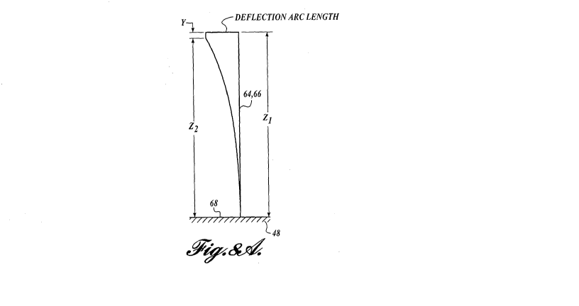
The 3D motion of a single bristle will now be described in more detail with
reference to FIGURES 8A-8B. FIGURES 8A-8B depicts a single bristle at an
outermost
radius of an oscillating brush with 6 degrees of rotation in one direction or
typically about
12 degrees overall. When an individual tuft of, for example, an oscillating
brush is
subjected to a rapid change in directional drive, one or more of the bristles
(i.e.,
filaments) will bend as represented in FIGURE 8A. This results in a z-axis
distance (i.e.,
the distance along the Z-axis) between the distal, free end or tip of the
bristle and the
anchored, proximal end of the bristle that varies throughout its oscillating
cycle due to
flexing or bending. As such, the distal tip of the bristle begins at a
distance Z1 from its
corresponding anchored proximal end in a static or at rest condition, and as
the bristle
bends due to oscillation of the brush head, the z-axis distance of the distal
tip of the
bristle shortens to a distance Z2. Typically, the distance Z1 is substantially
equal to the
bristle's length. In other words, the difference in the z-axis distance
between the bristle
tip and its corresponding anchored, proximal end when oscillated as compared
to a static
condition of the bristle can be referred to as the foreshortened z-axis
distance (Z1 minus
Z2 or Delta Z), and is denoted Y in FIGURE 8A.
When the applied inertial bending force on a tuft results from a brush
oscillating
about an axis, the inertial bending force will have a direct relationship of r-
theta position
for the tuft location on a brush base as distanced from the center of rotation
of the motor
drive, frequency of oscillation and deflection angle. For some brushes, the
representative
brush heads of the present disclosure will provide 3D motion either when the
brush is
fully rotational or oscillating.
In the representative brush heads of the present disclosure, the 3D motion
described herein as a function of bristle length (i.e., foreshortened z-axis
distance/bristle
-9-
CA 02952991 2016-12-19
WO 2014/207503 PCT/1B2013/002427
length) is approximately 0.03 or greater. For example, in embodiments of the
present
disclosure, the foreshortened z-axis distance Y is typically greater than
0.005 inches
(0.127 millimeters) but less than about 0.08 inches (2.032 millimeters), and
the bristle
length is typically greater than about 0.20 inches (5.08 millimeters) but
typically less than
about 1.20 inches (30.48 millimeters). In other embodiments, the foreshortened
z-axis
distance Y is greater than about 0.08 inches (2.032 millimeters) and the
bristle length is
greater than about 1.20 inches (30.48 millimeters).
Examples of different bristle heights oscillated at 6 degrees and the
resulting
foreshortened z-axis distance Y (See FIGURE 8A) is shown in TABLE 1. The
results in
TABLE 1 were arrived with the following assumptions: (1) deflection at the tip
of strand
is constant regardless of strand length; (2) inertial effects of resonant
motion were
excluded from model; (3) analysis assumes strand centerline without
considering strand
thickness or bending modulus; and (4) strand is fixed at base and remains
perpendicular
at base of strand.
TABLE 1.
Deflection in Deflection Arc
Foreshortened Z-Axis
Bristle Length (Z1)
Degrees Length Length (Y)
.325 6 0.058 .0086
.375 6 0.058 .0075
.425 6 0.058 .0065
.525 6 0.058 .0053
FIGURE 11 illustrates the effect of bristle dimensions on the force applied by
a
single bristle operated by an oscillating motor. Specifically, as the diameter
increases
from 0.003 inches (0.762 millimeters) to 0.005 inches (1.27 millimeters), the
force
applied also increases. Embodiments of the present disclosure or= others may
provide a
3D motion to the skin as the brush head is held gently to the skin, with
applied forces in
the range of 80 grams to 150 grams, more typically about 110 grams.
Traditionally, the
bristle tip effects are tangential to the surface of the skin, providing a
gentle stretch and
compression of the epidermis.
Returning to FIGURE 2-4, the brush head 20 further includes an optional outer
retainer 76. The outer retainer 76 includes a central, cylindrically shaped
opening 78.
-10-
CA 02952991 2016-12-19
WO 2014/207503 PCT/1B2013/002427
The opening 78 is sized and configured to surround the sides of the movable
central
portion 44. When attached to the appliance 22, a rim 80, which extends around
the top
periphery of the central opening 78, is flush with or positioned slightly
above the
outwardly facing surface of the body 48.
In some embodiments, the central portion 44 and the outer retainer 76 together
include an attachment system configured to provide selective attachment of the
brush
head 20 to the head attachment portion 28 of the personal care appliance 22.
When
attached to the personal care appliance 22 by the attachment system, the
following
occurs: (1) the movable central portion 44 is operatively connected to the
drive motor
assembly 30, for example, via a drive boss 52, in a manner that provides
oscillating
motion thereto; and (2) the outer retainer 76 fixedly secures the brush head
20 to the head
attachment portion 28 of the appliance 22. Accordingly, the attachment system
in some
embodiments provides a quick and easy technique for attaching and detaching
the brush
head 20 to the personal care appliance 22. It will be appreciated that the
attachment
system also allows for other personal care heads to be attached to the
appliance, and
allows for replacement exfoliating brush heads 20 to be attached to the
appliance, when
desired.
It will be appreciated that any attachment system can be employed to provide
either tooled or tool-less techniques for selectively attaching the brush head
20 to a
personal care appliance, such as appliance 22, in a manner that (1) provides
oscillating
motion to the central portion 44; and (2) maintains the connection between the
central
portion 44 and the drive motor assembly 30. For example, in some embodiments,
the
central portion 44 includes a coupling interface configured to cooperatingly
connect to an
oscillating drive shaft or armature, such as armature 42, of an associated
drive motor
assembly 30 in a manner that transmits oscillating motion to the central
portion 44 while
fixedly securing the central portion 40 thereto. As such, it should be
understood that
while the retainer 76 may provide certain benefits to some embodiments of the
brush
head 20, it is optional, and thus, it may be omitted, if desired.
The above-described examples of the brush head 20 can be used to clean,
massage, and/or exfoliate a subject's skin. In that regard, any brush head
herein disclosed
is first attached to the personal care appliance 22. The personal care
appliance 22 is then
turned on and the attached brush head is operated at sonic frequencies in the
range of
-11-
CA 02952991 2016-12-19
WO 2014/207503 PCT/1B2013/002427
about 40-350 Hz, oscillating the brush head back and forth within a range of
about 3-45
degrees.
Once oscillating, the brush head is applied against the skin on the body, such
as
on the face. Once the skin is treated to the desired amount, the brush head
can be
removed from the skin and the appliance 22 can be powered down. Alternatively,
the
appliance 22 can be powered down automatically via a programmed operation.
The methods of operation described above can be carried out with or without
the
use of skin care formulas or washing of the skin in warm water in an attempt
to soften the
skin. However, any preparation of the skin area prior to treatment can be used
as part of
the methods disclosed above.
It should be noted that for purposes of this disclosure, terminology such as
"upper," "lower," "vertical," "horizontal," "inwardly," "outwardly," "inner,"
"outer,"
"front," "rear," etc., should be construed as descriptive and not limiting the
scope of the
claimed subject matter. Further, the use of "including," "comprising," or
"having" and
variations thereof herein is meant to encompass the items listed thereafter
and equivalents
thereof as well as additional items. Unless limited otherwise, the terms
"connected,"
"coupled," and "mounted" and variations thereof herein are used broadly and
encompass
direct and indirect connections, couplings, and mountings.
The principles, representative embodiments, and modes of operation of the
present disclosure have been described in the foregoing description. However,
aspects of
the present disclosure which are intended to be protected are not to be
construed as
limited to the particular embodiments disclosed. Further, the embodiments
described
herein are to be regarded as illustrative rather than restrictive. It will be
appreciated that
variations and changes may be made by others, and equivalents employed,
without
departing from the spirit of the present disclosure. Accordingly, it is
expressly intended
that all such variations, changes, and equivalents fall within the spirit and
scope of the
present disclosure, as claimed.
-12-