Note: Descriptions are shown in the official language in which they were submitted.
MOTORIZED GIFT CARD HOLDERS
RELATED APPLICATIONS
This application is a first divisional of Canadian patent application number
2,914,034 filed on December 3, 2015.
FIELD OF THE INVENTION
This invention is in the field of social expression products. More
specifically,
this invention is directed to gift packaging in the form of gift card holders
having
motorized movement.
SUMMARY OF THE INVENTION
The present disclosure and related inventions are directed to various types of
motorized gift card holders. Each gift card holder embodiment creates added
entertainment value to the act of presenting a recipient with a gift card. In
some
embodiments, the gift card holder is in the form of a greeting card having a
motor therein
to which a gift card or gift card sleeve is attached. In other embodiments,
the gift card
holder is in the form of a box having a motor therein to which a gift card or
gift card
sleeve is attached. Audio playback accompanies the motor movement of the gift
card or
gift card sleeve.
We further disclose a gift card holder comprising:
a) a greeting card having at least three flaps contained thereon, wherein
opening a
first flap reveals a second flap, opening the second flap reveals a third flap
and opening
the third flap reveals a mobile object and a gift card sleeve for removably
containing a
gift card therein; and
b) a motor contained and concealed within the greeting card, the motor
operative to
cause movement of the mobile object and the gift card sleeve.
The motor is activated upon opening the third flap.
We further disclose a gift card holder comprising:
1
CA 2953081 2018-01-17
a frame concealed beneath one or more panels;
a first flap contained on one of the one or more panels;
a second flap contained beneath the first flap;
a third flap contained beneath the second flap; and
a gift card sleeve contained beneath the third flap.
The gift card sleeve is connected to a motor contained and concealed within
the frame
and beneath the one or more panels, the motor operative to cause movement of
the gift
card sleeve, and
the motor is activated upon opening the third flap. The gift card hold may
further
comprise a mobile object attached to the motor and the gift card sleeve.
DESCRIPTION OF THE DRAWINGS
FIG. 1 is a perspective view of a first embodiment of a motorized gift card
holder of the
present invention, in an open position.
la
CA 2953081 2018-01-17
CA 02953081 2016-12-28
FIG. 2 is a front tear-away view of the gift card holder of FIG. 1.
FIG. 3 is a front view of the inside of a second embodiment of the present
invention.
FIG. 4 is an exploded view of the gift card holder of FIG. 3.
FIG. 5 is a perspective view of a third embodiment of the present invention,
in a closed
position.
FIG. 6 is a perspective view of the gift card holder of FIG. 5, in an open
position.
FIG. 7 is a front tear-away view of the gift card holder of FIG. 5.
FIG. 8 is a profile view of the switch of the gift card holder of FIG. 5, in a
first position,
from the perspective of arrows 8-8.
FIG. 9 is a profile view of the switch of the gift card holder of FIG. 5, in a
second
position.
FIG. 10 is a perspective view of the motor of the gift card holder of FIG. 5.
FIG. 11 is a perspective view of a fourth embodiment of the present invention,
in a
closed position.
FIG. 12 is a perspective view of the gift card holder of FIG. 11, in an open
position.
FIG. 13 is a perspective tear-away view of the gift card holder of FIG. 11.
FIGS. 14 through 17 are alternate motors which can be used in any of the four
gift card
holder embodiments of the present invention.
DETAILED DESCRIPTION OF PREFERRED AND ALTERNATE
EMBODIMENTS
The present disclosure and related inventions are directed to gift packaging
in the
form of gift card holders. Gift card holders can come in the form of a
greeting card
having some type of attachment mechanism such as slots, a sleeve, a pocket,
glue, etc. in
or onto which a greeting card may be placed. Gift card holders can also come
in the form
of a gift box or other such carrying or holding device. Each of the gift card
holders
described herein contain a small motor which when activated causes movement to
a
mobile element located somewhere on the greeting card. In many embodiments,
the gift
card itself is in some way, either directly or indirectly, attached to the
motor causing
movement of the actual gift card itself. Various embodiments which include a
variety of
packaging options and a variety of special effects are described herein. The
embodiments
2
CA 02953081 2016-12-28
described herein each add extra entertainment value to the process of gifting
a gift card to
a recipient.
As used herein, the term "gift card" is defined as being a restricted monetary
equivalent issued by retailers or banks to be used as an alternative to a non-
monetary gift.
Gift cards are legal tender purchased for use by a consumer and useable in its
face
amount in lieu of cash in exchange for goods and services supplied by the
seller. Gift
cards typically resemble a credit card or display a specific theme on a
plastic card having
a magnetic strip or bar code thereon (typically on the back surface thereof)
which
contains the dollar amount of the gift card. This amount is rarely stored on
the card itself
but instead stored in a database controlled by the seller and cross-linked to
the ID stored
on the magnetic strip or bar code. "Open loop" gift cards are issued by banks
or credit
card companies and can thus be redeemed at different establishments. "Closed
loop" gift
cards are issued by a specific retailer or restaurant and can only be redeemed
by the
issuing provider. Gift cards can be "reloadable" wherein once the dollar
amount has
been used, additional amounts can be added to the card such that the same gift
card can
be used multiple times. The term "gift card" can be used interchangeably with
the term
"transaction card". While not all gift cards are stored value cards (dollar
amount actually
stored on the card itself), stored value cards are intended to be included
under the term
"gift cards" as used herein.
While the present invention is deemed "motorized gift card holders", the
embodiments described herein are also intended to cover other non-gift card
items which
can be held in the "gift card sleeve" or other holding or containment
mechanism
described herein for holding a gift_card. Such non-gift card items include,
but are not
limited to: cash, gift certificates, checks, vouchers, coupons, notes, lottery
tickets, tickets
to entertainment events (e.g. sporting events, movies, concerts, lectures,
conferences,
etc.) calling cards, business cards, collectable cards, small gift items, and
cards or coins
or other substrate with a QR code, digital watermark, bar code (or other
digital code or
mark which can be decoded printed thereon) having stored therein or being
linked to
digital or electronic content such as games, music, videos, movies, books,
magazine
subscriptions, photographs, or other such digital content.
3
CA 02953081 2016-12-28
In each of the motorized gift card holder embodiments described herein, a
small
motor is typically concealed within the body of the gift card holder. The body
may be in
the form of a traditional greeting card having one or more greeting card
panels or may be
in the form of a box, a pocket, a sleeve or other such container. In all
cases, a small
motor is concealed within the body of the gift card holder. The motor is
relatively small
and lightweight so as to fit within each gift card holder and not add
significantly to the
weight or bulk of said gift card holder. As an example, the motors may be of
the type
shown in FIGS. 10 and 14 through 17. In one example, the motor includes a
rotating
arm or shaft which may be an offset shaft which creates oscillatory motion
upon rotation
of the shaft by the motor. A lightweight attachment mechanism is attached at
one side to
the rotating arm or shaft of the motor and at an opposite side to a mobile
object. The
motor may alternatively have a rotating gear mechanism that when activated
turns a
circular gear. A connecting rod is located between and connects the gear and
the mobile
object. As the gear is rotated by the gear mechanism, it in turn causes the
mobile object
to rotate or spin. These examples of various miniature motor types are set
forth herein as
an illustration only and is not meant to limit the invention in any way. Any
type of small,
lightweight motor can be used.
In a first embodiment, shown in FIGS. 1 and 2, the gift card holder 100 is in
the
form of a greeting card 10 having three panels. Each panel contains a front
surface and a
rear surface opposite the front surface. A first panel 10A is attached to a
second panel
(not shown) along a first fold line and a third panel 10B is attached to the
second panel
(not shown) along a second fold line. The third (rightmost) panel 10B is
folded over the
second (center) panel about the second fold line such that the front surface
of the third
panel 10B is facing the front surface of the second panel. The third panel 10B
is
attached, adhesively or otherwise, to the second panel about each free
perimeter edge,
creating a closed pocket or cavity therebetween. The rear surface of the first
panel 10A
serves as the front cover of the greeting card 10 as it is folded over the
second and third
10B panels (which are attached) along the first fold line. The front surface
of the first
panel 10A serves as the inside left panel of the greeting card 10. The rear
surface of the
third panel 10B serves as the inside right panel of the greeting card 10 and
the rear
surface of the second panel serves as the back or rear cover of the greeting
card 10. The
4
CA 02953081 2016-12-28
first panel (or front cover of the greeting card) 10A may contain an opening
thereon
through which a portion of the inside right panel (and attached gift card) is
visible.
Various electronic components of the greeting card are contained within the
closed
pocket or cavity created between the second and third greeting card panels.
The
electronic components may include, but are not limited to: a printed circuit
board 12, an
integrated circuit chip, a speaker 14, a switch, a power source such as one or
more
batteries 16, a motor 18, a memory device and related circuitry and wiring.
Any other
component which is required to or which facilitates audio capabilities, motor
movement,
or any other special effect, such as lighting, may be included, such
components being
known to one having skill in the art. A gift card sleeve or pocket 20 having
three closed
sides and one open side is attached to the motor 18 via a connecting rod or
arm through
an opening in the third panel 10B of the greeting card 10 (inside right panel)
so that the
gift card sleeve or pocket 20 is located on the inside right panel of the
greeting card 10.
In a preferred embodiment, the gift card sleeve or pocket 20 is rectangular
shaped
(similar but slightly larger than the size of a traditional gift card) having
an opening along
the right edge thereof for insertion and removal of the gift card. The front
surface of the
gift card sleeve or pocket 20 may be completely or partially transparent so
that the
recipient can view a gift card contained with the gift card sleeve or pocket
20. The
opening on the gift card sleeve or pocket 20 may alternatively be placed along
the top
edge of the sleeve. Also, instead of having a sleeve or pocket 20 with an open
edge, the
sleeve or pocket 20 may have a flap which can be lifted to reveal a gift card
inside the
sleeve or pocket or a slot which can be contained on a front face of the
sleeve or pocket
20 or any such opening for inserting and removing a gift card. The gift card
pocket or
sleeve 20 may contain printed indicia thereon or may contain embellishments
such as
googly eyes 22, a Santa Claus hat, a birthday party hat, or other such
embellishments.
The gift card sleeve or pocket 20 is attached either directly to the motor 18
or to a
connection arm which is also attached to the motor 18. In a preferred
embodiment, the
greeting card 10 contains a slide switch 13 attached to the greeting card 10
across the
first fold line so that when the greeting card 10 is opened but unfolding the
first panel
(cover panel) 10A away from the second and third 10B panels (rear panel), the
slide
switch 13 completes the circuit causing activation of the motor module,
thereby putting
5
CA 02953081 2016-12-28
the gift card pocket or sleeve 20 in motion. The motion may be an up-and-down
bouncing or vibrating motion, a back-and-forth motion or a circular rotating
or spinning
motion. In addition to activating the motor 20, the slide switch 13 may also
control
activation of a sound module which causes audio to be emitted from the speaker
14. At
least one audio file may be contained on a memory device within the greeting
card 10.
Alternatively, the greeting card 10 may contain additional components such as
a
microphone and recording device which can be implemented to allow a user to
record a
personalized message for playback upon opening the greeting card. When the
greeting
card 10 is presented to a recipient, the gift card sleeve or pocket 20 is
visible through an
opening on the front panel 10A of the greeting card 10. Opening the greeting
card 10
initiates the motor 18 and sound module so that the gift card sleeve or pocket
20 (and gift
card contained therein) begin moving and audio is emitted through the speaker
14. The
motor 18 and sound will continue until a certain predetermined period of time
or until the
user closes the greeting card 10. While the greeting card/gift card holder has
been
described herein as having a slide switch which activates the motor and sound
module
upon opening the greeting card, other switch mechanisms may be used such as a
push-
button switch, a touch sensitive switch, a light sensitive switch, an audio
sensitive
switch, a motion-sensitive switch, or any other type of switch mechanism.
Also, the
greeting card may contain a different number of greeting card panels than what
has been
disclosed herein with respect to the preferred embodiment. The gift card
sleeve or pocket
may have a different shape or insertion and removal method than those
described herein.
Such changes or substitutions have been contemplated and are considered to be
within
the scope of the present invention. Also, instead of the gift card holder
being in the form
of a greeting card, the gift card holder may alternatively be in the form of a
gift bag. The
gift bag being shaped like a traditional gift bag having four side panels, one
closed end
and one open end for inserting and removing gifts or other items therefrom.
One of the
gift bag panels may be double-walled with a cavity between the two walls of
the panel
wherein the motor and other electronic components (mentioned above) may be
contained. The gift card sleeve is attached to the motor through an opening in
the gift
bag such that the gift card sleeve is contained on the outside of the gift
bag. A press
button, or other type of switch may be used in place of the slide switch
described above.
6
CA 02953081 2016-12-28
In an alternate configuration, this embodiment may also be contained within a
gift box
instead of greeting card or gift bag.
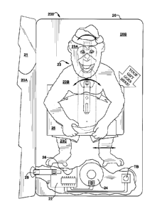
In a second embodiment, shown in FIGS. 3 and 4, similar to the first
embodiment
described directly above, the gift card holder of the present invention is
also in the form
of a traditional greeting card 20. Each panel contains a front surface and a
rear surface
opposite the front surface. A first panel 20A is attached to a second panel
(not shown)
along a first fold line and a third panel 20B is attached to the second panel
along a second
fold line. The third (rightmost) panel 20B is folded over the second (center)
panel about
the second fold line such that the front surface of the third panel 20B is
facing the front
surface of the second panel. The third panel 20B is attached, adhesively or
otherwise, to
the second panel about each free perimeter edge, creating a closed pocket or
cavity
therebetween. The rear surface of the first panel 20A serves as the front
cover of the
greeting card 20 as it is folded over the second and third panels 20B (which
are attached)
along the first fold line. The front surface of the first panel 20A serves as
the inside left
panel of the greeting card 20. The rear surface of the third panel 10B serves
as the inside
right panel of the greeting card 20 and the rear surface of the second panel
serves as the
back or rear cover of the greeting card 20. The first panel (or front cover of
the greeting
card) 20A be smaller than the second and third 20B panels such that a portion
of the
inside right panel (or something attached thereto) is visible from the front
of the closed
greeting card 20. In a preferred embodiment, a transparent panel 21 is
attached to an
upper portion of the first (or front) greeting card panel 20A. As mentioned
above with
respect to the first embodiment, various electronic components of the greeting
card are
contained within the closed pocket or cavity created between the second and
third
greeting card panels. The electronic components may include, but are not
limited to: a
printed circuit board 22, an integrated circuit chip, a speaker 24, a switch,
a power source
such as one or more batteries 26, a motor 28, a memory device and related
circuitry and
wiring. Any other component which is required to or which facilitates audio
capabilities,
motor movement, or any other special effect, such as lighting, may be
included, such
components being known to one having skill in the art. A mobile object 23 is
attached to
the motor 28 through an opening on the third panel (or inside right panel) 20B
of the
greeting card 20. The mobile object 23, in this embodiment is two or more die
cut
7
CA 02953081 2016-12-28
shapes which are shaped, printed and arranged to resemble an animal, character
or other
animate object (e.g., a monkey, a dog, a clown, a cartoon character, a
celebrity, a car, an
airplane). As an example, as shown in FIGS. 3 and 4, the mobile object 23
includes
three die-cut shapes which are attached, either directly or indirectly, to a
motor 28. In the
example shown, there is a first die cut shape 23A (resembling the head of a
monkey)
which is attached to a second die cut shape 23B (resembling the arms and upper
torso of
a monkey) and a third die cut shape 23C (resembling the legs and of a monkey).
The
second die cut shape 23B and the third die cut shape 23C are each separately
attached to
the motor 28 (in this example, via a backing panel 27A and attachment arm 27B)
at
separate pivot points Pl, P2. The pivot points Pl, P2 allow the die cut shapes
23A, 23B,
23C to separately move when the motor 28 is activated. The first die cut shape
23A is
also independently attached to the greeting card 20 via a spring S or other
attachment
mechanism which still allows for movement of the first die cut shape 23A. A
gift card
sleeve 25 is attached to the second die cut shape 23B, the gift card sleeve 25
being
generally rectangular with four closed sides and one open side along the right
side
thereof The gift card sleeve 25 is dimensioned to fit a traditional or
standard-sized gift
card (slightly larger than the standard sized gift card). The gift card can
easily be inserted
and removed from the sleeve 25 via the one open side of the sleeve 25. The
gift card
sleeve 25 is attached to the second die cut shape 23B (which resembles the
monkey's
arms) to appear as though the monkey is holding the gift card sleeve 25 (and
gift card
therein). The motor 28 may be activated upon opening the greeting card 20. A
slide
switch 29 may be located across the first fold line between the first and
second greeting
card panels such that when the greeting card 20 is opened, the motor 28 is
activated. The
slide switch 29 may also control activation of a sound module which is
operative to store
and playback at least one audio file. The audio file, mobile object 23 and
greeting card
20 may be coordinated to convey a particular theme. For example, the mobile
object 23
resembles a monkey while the audio file contains sounds of a monkey. The
greeting card
20 may contain artwork or other printing thereon in keeping with the monkey
theme. In
an alternate embodiment, the sound module and motor 28 may be controlled by
separate
switches. The inside of the greeting card 20 may additionally contain a push
button or
"turbo" button TB, which when pressed, increases speed of the motor 28 and
mobile
8
CA 02953081 2016-12-28
object 23. The speed of the audio replay may also increase in response to the
user
pushing the "turbo" button TB. Pressing the "turbo" button TB a second time,
slows the
motor 28 and audio back to the original speed. The greeting card 20 may
contain
printing thereon indicating the location of the "turbo" button TB so the user
is aware that
pushing on that area of the greeting card 20 will cause further entertaining
effects.
Closing the greeting card 20 will cause deactivation of the motor 28 and sound
module.
While the mobile object 23 has been described herein as having three die cut
shapes 23A,
23B, 23C connected to a motor 28 two separate pivot points P1, P2, the mobile
object 23
may contain any number of die cut shapes and the shapes may be attached at one
or more
pivot points. The die cut shapes may be attached directly to the motor 28 or
they may be
attached to a backing panel 27 which is attached to the motor 28 or to a
connecting arm
between the motor 28 and backing panel 27. This embodiment may also be used on
a
gift bag. The gift bag may be of the traditional sort having four side panels,
one closed
end and one open end for the insertion and removal of a gift or other item
therein. At
least one of the four side panels may be double walled with a cavity between
the two
walls of the panel wherein a motor and other electronic components (mentioned
above)
may be contained. The mobile object and gift card sleeve may be attached to
the motor
through an opening in the greeting card panel such that the mobile object and
give card
sleeve are contained on an outside surface of the gift bag, preferably on the
front face of
the gift bag. A switch, such as a push-button switch may be used to activate
the motor
and optional sound module. Other switches may be used in place of the push-
button
switch. In an alternate configuration, this embodiment may also be contained
within a
gift box instead of greeting card or gift bag.
In a third embodiment, shown in FIGS. 5 through 10, the gift card holder of
the
present invention is also in the form of a greeting card. This greeting card
30 contains
various doors or flaps thereon which can be opened in a particular sequence
such that
when the last door or flap is opened a gift card sleeve 31 (for holding a gift
card) is
revealed and said gift card sleeve 31 is set in motion. Audio may also be
initiated upon
opening the last door or flap. In a preferred embodiment, the greeting card 30
contains
multiple greeting card panels which are wrapped and attached about a frame.
The frame
is substantially rectangular-shaped and in a preferred embodiment is made of
foam but
9
CA 02953081 2016-12-28
can be made of cardboard, paperboard or other lightweight material. Electronic
components of the greeting card are contained on the inside of the frame
beneath the
greeting card panels which cover the entire frame. The electronic components
may
include, but are not limited to: a printed circuit board 32, an integrated
circuit chip, a
speaker 34, a switch, a power source such as one or more batteries 36, a motor
38, a
memory device and related circuitry and wiring. Any other component which is
required
to or which facilitates audio capabilities, motor movement, or any other
special effect,
such as lighting, may be included, such components being known to one having
skill in
the art. The front face of the greeting card contains a flap Fl (also referred
to herein as a
"door") thereon which covers a significant portion of the front cover of the
greeting card
30. The flap Fl may contain a semi-circular tab thereon for gripping to open
the flap Fl.
Opening the first flap Fl reveals a second, smaller sized flap F2. Opening the
second
flap F2 reveals a third flap F3. Opening the third flap F3 reveals a mobile
object 33 with
a gift card sleeve 31 attached thereto. Opening the third flap F3 causes
activation of a
motor 38 which is attached to the mobile object 33. It may also activate a
sound module
which is operative to store and replay at least one audio file. The first Fl,
second F2 and
third F3 flaps may all be part of the same panel which are cut and folded into
a stacked
arrangement. Each flap Fl, F2, F3 may be opened in different directions. For
example,
in a preferred embodiment, the first flap Fl is opened by folding the first
flap Fl from
left to right, the second flap F2 is opened by folding the second flap F2 from
right to left
and the third flap F3 is opened by folding the third flap F3 in a downward
direction.
Each of the three flaps Fl, F2, F3 may contain portions of a greeting or
message thereon
or may contain other sequential or random printing or artwork thereon. A slide
switch 35
is attached to the third F3 or final flap such that when that flap F3 is
opened or folded
downward, the slide switch 35 activates the motor 38, causing movement of the
mobile
object 33 (and gift card sleeve 31) and also activating the sound module
causing replay of
the at least one audio file through the speaker 34. As shown in FIG.9, when
the third
flap F3 is in a first or closed position, the tongue portion 35A of the side
switch 35 is
inserted between the two electrical contacts 35B, 35C, thereby breaking the
circuit.
When the third flap F3 is opened or folded downward, the third panel F3 pulls
the tongue
portion 35A of the slide switch 35 from between the two electrical contacts
35B, 35C,
CA 02953081 2016-12-28
thereby completing the circuit, activating the motor 38 and sound module, as
shown in
FIG. 8. In a preferred embodiment, the mobile object 33 moves in an up-and-
down or
"bouncing" motion but the mobile object 33 may move in any patter such as back-
and-
forth, vibrating motion, etc. A gift card sleeve 31 is attached to the front
surface of the
mobile object 33 and appears as though the character depicted on the mobile
object 33 is
holding or carrying the gift card sleeve 31. The gift card sleeve 31 is
basically
rectangular having three closed sides and one open side along the right side
of the sleeve
31 for the insertion and removal of a traditional, standard sized gift card.
While this
embodiment has been described herein as having three flaps or doors Fl, F2,
F3, any
number of flaps may be used and the flaps can open in the same or different
directions.
This embodiment may also be used with a gift bag. The gift bag may be of the
traditional
kind having four closed side panels, one closed end and one open end for the
insertion
and removal of a gift or other item therein. At least one of the side panels
of the gift bag
may be double-walled having a cavity therebetween wherein the motor and other
electronic components (mentioned above) may be contained. The flaps are
contained on
an outside surface of the gift bag, preferably the front face of the gift bag.
The gift card
or gift card sleeve may be attached to the motor through an opening in the
gift bag. A
push button switch or other type of switch may be used to activate the motor
and optional
sound module. In an alternate configuration, this embodiment may also be
contained
within a gift box instead of greeting card or gift bag.
In a fourth embodiment, shown in FIGS. 11 through 13, the gift card holder is
in
the form of a box. The box 40 contains a hinged lid L which when opened
reveals a gift
card (or gift card sleeve with gift card contained therein) 41 attached to a
rotating spring
43 at the center of the box 40. The box 40 contains a box portion 40B and a
lid 40L
attached to the box portion 40B. The box portion 40B contains four perimeter
sides PB
which extend upward from a bottom panel (not shown) of the box 40. A floor
panel F
which extends perpendicularly between the four perimeter sides PB of the box
portion
40B, creates a small hidden compartment between the bottom panel (not shown)
of the
box 40 and the floor panel F which contains the electronic components of the
gift card
holder 400. The electronic components may include, but are not limited to: a
printed
circuit board 42, an integrated circuit chip, a speaker 44, a switch, a power
source such as
11
CA 02953081 2016-12-28
one or more batteries 46, a motor 48, a memory device and related circuitry
and wiring.
Any other component which is required to or which facilitates audio
capabilities, motor
movement, or any other special effect, such as lighting, may be included, such
components being known to one having skill in the art. The compartment is
covered by
the planar floor panel F having an opening thereon through which the spring 43
exits.
The floor panel F can be have printing or other indicia thereon which matches
or is
coordinated with the theme of the gift card holder 400. A spring mechanism 43
is
attached at one end to a motor 48 contained in the hidden compartment beneath
the floor
panel F of the box 40. A u-shaped channel 55 or clip, which is operative to
removably
contain a gift card (or sleeve with gift card therein) 41 therein is attached
to the opposite
end of the spring mechanism 43. The channel 55 or clip may contain die cut
shapes on
each side of the channel or other decorative effect, as shown in FIG. 12. The
spring
mechanism 43 bends and folds over (causing the gift card 41 to be in a
horizontal or
prone position beneath the lid 40L) when the lid 40L closed or is contained
atop the gift
box 40. The lid portion 40L of the box 40 contains three perimeter sides PL.
Two of the
perimeter sides PL, which cover the sides of the box, may be tapered from
front to back,
to facilitate easy opening and closing of the lid portion 40L of the box 40.
Upon a user
opening the box 40, the spring 43 unfolds and stands straight up (causing the
gift card 41
to be in a vertical or upright position) and begins to rotate. The inside
surface of the
attached lid 40L portion of the box 40 contains a slightly outwardly bowed or
curved
panel C which facilitates the movement of the spring 43 and gift card 41 from
the first
(flat, folded) positon, when the lid 40L is closed or atop the box portion B
and the
second (unfolded, upright) position, when the lid 40L is opened or removed
from atop
the box portion 40B. The curved inner panel C on the inside surface of the lid
40L
prevents the gift card 41 from catching or interfering with the perimeter
sides of the lid
portion 40L of the box 40. A small magnet M may be placed inside the front
perimeter
side PB of the box portion 40B of the box 40 and also inside the front
perimeter side PL
of the lid portion 40L of the box 40. When the lid portion 40L is closed or
placed atop
the box portion 40B, the front perimeter of the lid PL covers the front
perimeter of the
box PB such that the two magnets M come into close contact thereby attracting
each
other and removably securing the lid portion 40L in place atop the box portion
40B. The
12
CA 02953081 2016-12-28
magnets also serve as a trigger or magnetic switch. When the two magnets M are
in
contact, such as when the lid 40L is closed atop the box 40B, the circuit is
interrupted but
when the two magnets M are not in contact, such as when the lid 40L is opened
or
removed from atop the box 40B, the circuit is completed, thereby triggering
activation of
the sound and motor modules. Therefore, when the user opens the box 40 by
removing
the lid portion 40L from the box portion 40B, the magnetic switch activates
the sound
module so that the at least one audio file contained in memory in the sound
module is
replayed through the speaker 44 and the motor 48 is activated, thereby causing
the spring
mechanism 43 (and greeting card 41) to rotate. Closing the box 40, by placing
the lid
portion 40L back atop the box portion 40B, deactivates the motor 48 and sound
module.
In all of the embodiments disclosed herein, the "gift card sleeve" may be
empty
for the insertion of a separately purchased gift card or may have a pre-
packaged gift card
contained therein. Also, instead of having a gift card sleeve for storing of a
gift card
therein, the gift card sleeve may be replaced by the gift card itself. The
gift card may be
releaseably connected to a motor or to a connection mechanism between the gift
card and
the motor.
The foregoing embodiments of the present invention have been presented for the
purposes of illustration and description. These descriptions and embodiments
are not
intended to be exhaustive or to limit the invention to the precise form
disclosed, and
obviously many modifications and variations are possible in light of the above
disclosure.
The embodiments were chosen and described in order to best explain the
principle of the
invention and its practical applications to thereby enable others skilled in
the art to best
utilize the invention in its various embodiments and with various
modifications as are
suited to the particular use contemplated. It is intended that the invention
be defined by
the following claims.
13