Note: Descriptions are shown in the official language in which they were submitted.
CA 02953083 2016-12-20
1
DESCRIPTION
Rhinal Spray Nozzle used for Medical Syringe
Technical Field
[0001] The present invention relates to a rhinal spray
nozzle used for a medical syringe to apply a viscous
pharmaceutical formulation to a rhinal mucosal membrane.
Background Art
[0002] So far a metered-dose syringe-based squirt has
been suggested for application as a rhinal spray nozzle.
For example, Patent Document 1 (i.e., WO 2013/145789 Al)
discloses the metered-dose syringe squirt which comprises a
syringe, a plunger being squeezable within the syringe, an
elastic-deformation member being elastically deformable by
squeezing the plunger within the syringe, and a stopper
which is stopped against the syringe and released by
restoring force of the elastic-deformation member, whereby
the fluid content filled in the single syringe can be
delivered at multiple steps by squeezing and releasing the
plunger.
[0003] Also,
although it is not the syringe-based squirt,
an airless spray container (e.g., rhinal spray container)
has also been proposed to apply a viscous pharmaceutical
formulation to a rhinal mucosal membrane. For example,
Patent Document 2 (JP 5185109 B) discloses an upside back-
2
pressure airless spray container being operable to control
a spray angle and a spray distribution in a desired range
thereof when spraying a gel base material comprising carboxy
vinyl polymer which was treated by applying an exogenous
shear force.
Summary
[0003a] Certain exemplary embodiments provide a rhinal
spray nozzle for use with a medical syringe having a tip
opening in fluid communication with a syringe barrel for
storing a formulation, the rhinal spray nozzle comprising:
a hollow nozzle body having a tip portion defining a nozzle
orifice thereon; a solid packing rod arranged within the
nozzle body; and a nozzle chamber defined between the packing
rod and the nozzle body to allow a fluid communication
between the tip opening and the nozzle orifice; wherein the
formulation comprises a gel material comprising a viscosity
modification agent and a carboxy vinyl polymer of which
viscosity can be modified by applying an exogenous shear
force, wherein the nozzle orifice has a diameter in a range
between 0.25 mm and 0.30 mm, wherein the packing rod has a
rod small-diameter portion and a rod large-diameter portion,
and a shoulder having a diameter step-wisely reducing from
the rod large-diameter portion towards the rod small-
diameter portion, wherein the packing rod includes a
plurality of grooves circumferentially spaced from one
CA 2953083 2019-11-22
3
another both on the rod small-diameter portion and on the
rod large-diameter portion, and wherein a gap is defined
between the packing rod and the nozzle body.
[0004] The
airless spray container being capable of
delivering a multiple metered-dose formulation has an
advantage in containing and storing a plurality of
formulation doses therein.
However in case where the,
pharmaceutical formulation is used as a prophylaxis or a
therapeutic medication for an infectious disease, most of
patients or vaccine recipients feel less comfortable and
less sanitary to share the airless spray container with the
nozzle inserted within their nasal cavities, which may also
cause any other infectious diseases (in-hospital infections).
[0005] The
present inventors have considered to use the
metered-dose syringe squirt of the aforementioned Patent
Document 1 for spraying the formulation containing the gel
base material comprising carboxy vinyl polymer treated by
applying an exogenous shear force.
However because the
metered-dose syringe squirt has a basic structure different
from that of the upside back-pressure airless spray container
(especially the spray nozzle thereof) disclosed in the
aforementioned Patent Document 2, a particular spray
characteristics such as a particle size distribution of
formulation, a uniform spray geometry, and a spray angle
CA 2953083 2019-11-22
3a
which is required for a targeted pharmaceutical benefits of
the formulation has not been achieved so far.
[0006] To address the aforementioned drawbacks, the
present inventors have finally made the present invention
after finding an optimized shape and configuration of the
nozzle of the metered-dose syringe-based squirt for spraying
the viscous formulation having pre-described features to the
rhinal mucosal membrane.
[0007] One of aspects of the present invention is to
provide a rhinal spray nozzle used for a medical syringe
having a tip opening in fluid communication with a syringe
barrel for storing a formulation, the rhinal spray nozzle
comprises a hollow nozzle body having a tip portion defining
a nozzle orifice thereon, a solid packing rod arranged
within the nozzle body, and a nozzle chamber defined
between the packing rod and the nozzle body to allow a
fluid communication between the tip opening and the
nozzle orifice, wherein the formulation comprises the
gel material containing viscosity modification agent and
carboxy vinyl polymer of which viscosity is modified by
CA 2953083 2019-11-22
CA 02953083 2016-12-20
4
applying an exogenous shear force, and wherein the nozzle
orifice has a diameter in a range between 0.25 mm and 0.30
MM.
[0008] Preferably,
the formulation comprises the gel
material containing the viscosity modification agent such
as sodium chloride or potassium chloride), a pH buffer
solution such as dibasic sodium phosphate hydrate and
sodium dihydrogenphosphate, and a neutralizing agent such
as L-Arginine and sodium hydroxide, of which viscosity is
modified by applying an exogenous shear force.
[0009] Also preferably the nozzle orifice includes
substantially no curved portion, and the tip portion has
thickness along an injection direction of the formulation
which is in a range between 0.20 mm and 0.30 mm.
[0010] Also preferably the
nozzle body includes an inner
wall having at least a portion formed in a cylindrical
shape and the packing rod includes an outer wall at least a
portion formed in a cylindrical shape having a plurality of
circumferentially spaced grooves, the nozzle chamber is
defined between the at least portion of 1he inner wall of
the nozzle body and the at least portion of the outer wall
of the packing rod, and the packing rod includes a vortex-
flow generation member opposed to the tip portion of the
nozzle body. The vortex-flow generation member formed so
that a flow direction of the formulation from the grooves
5
of the packing rod may be offset to a central axis, thereby
to generate a vortex flow of the formulation. Also
preferably, the at least portion of the inner wall of the
nozzle body is formed to have a cross section perpendicular
to the injection direction continuously or step-wisely
reducing towards the injection direction.
[0011] The gel
material preferably has a viscosity of
2500 mPas or less, and more preferably 1000 mPas. Preferably
a spray angle of the formulation sprayed from the nozzle
orifice is in a range 45 degrees and 60 degrees,
an average particle size of formulation droplets sprayed
from the nozzle orifice is in a range 50 microns and 80
microns. Also preferably, counts of formulation droplets
sprayed from the nozzle orifice having the particle size in
a range between 10 to 100 microns are 70.% or more of the
total counts of the particle.
Advantages of Invention
[0012] According to the present invention, it is
advantageous to achieve the given spray characteristics (a
particle size distribution, a uniform spray geometry, and a
spray angle) required to obtain a pharmaceutical benefits of
the formulation comprising the gel material containing
viscosity modification agent and carboxy vinyl polymer of
which viscosity is modified by applying an exogenous shear
force.
CA 2953083 2018-09-27
CA 02953083 2016-12-20
6
Brief Description of Drawings
[0013] Fig. 1 is a partially-fragmented side view of a
general structure of a medical syringe comprising a rhinal
spray nozzle of one embodiment according to the present
invention.
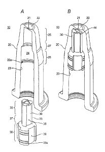
[0014] Figs. 2A and 2B are partially-fragmented
perspective views of the general structure of the rhinal
spray nozzle of one embodiment of the present invention,
showing configurations before and after the packing rod are
inserted within the nozzle body, respectively.
[0015] Fig. 3A is a vertical cross-sectional view of the
rhinal spray nozzle of Fig. 2B, and Figs. 3B, 3C and 3D are
horizontal cross-sectional views of the rhinal spray nozzle
taken along B-B line, C-C line and D-D line of Fig. 3,
respectively.
[0016] Figs. 4A and 4B are enlarged cross-sectional
views of the tip portion of the nozzle body, in which the
tip portion is provided with the curved portion in Fig. 4A
but not in Fig. 4B.
[0017] Fig 5 shows spray patterns of the formulation
sprayed from the nozzle orifice of Example 1.
[0018] Fig 6 shows a spray angle of the formulation
sprayed from the nozzle orifice of Example 1.
[0019] Fig 7 shows a particle size distribution of the
formulation sprayed frcm the nozzle orifice of Example 1.
CA 02953083 2016-12-20
7
[0020] Fig 8 shows the spray patterns of the formulation
comprising the base materials A in the metered-dose
syringe-based squirt provided with various rhinal spray
nozzles, and also indicate whether the combination of the
base material and the rhinal spray nozzles is acceptable or
not.
[0021] Fig 9 shows the spray patterns of the formulation
comprising the base materials Bl in the metered-dose
syringe-based squirt provided with various rhinal spray
nozzles.
[0022] Fig 10 shows the spray patterns of the
formulation comprising the base materials Cl in the
metered-dose syringe-based squirt provided with various
rhinal spray nozzles.
[0023] Fig 11 shows the spray patterns of the
formulation comprising the base materials C2 in the
metered-dose syringe-based squirt provided with various
rhinal spray nozzles.
[0024] Fig 12 shows the spray patterns of the
formulation comprising the base materials D in the metered-
dose syringe-based squirt provided with various rhinal
spray nozzles.
[0025] Fig 13 shows the spray patterns of the
formulation comprising the base materials El in the
metered-dose syringe-based squirt provided with various
CA 02953083 2016-12-20
8
rhinal spray nozzles.
[0026] Fig 14 shows the spray patterns of the
formulation comprising the base materials E2 in the
metered-dose syringe-based squirt provided with various
rhinal spray nozzles.
[0027] Fig 15 shows the spray patterns of the
formulation comprising the base materials E4 in the
metered-dose syringe-based squirt provided with various
rhinal spray nozzles.
Description of Embodiments
[0028] With
reference to attached drawings, embodiments
of a rhinal spray nozzle used for a medical syringe
according to the present invention will be described
hereinafter. In the
following description, directional
terms such as "front, "rear", "proximal" and "distal" are
conveniently used for better understandings, however those
terms are not intended to limit the scope of the present
invention. Also, like
components are denoted by like
reference signs throughout the attached drawings.
[0029] [Medical Syringe]
Fig. 1 is a partially-fragmented side view of a
medical syringe 1 comprising a rhinal spray nozzle 10 of an
embodiment according to the present invention. As
illustrated in Fig. 1, the medical syringe 1 generally
comprises a syringe body 4 made of synthetic resin or glass
CA 02953083 2016-12-20
9
having a syringe barrel 3 capable of storing a
pharmaceutical formulation therein, and a plunger rod 5
inserted within the syringe barrel 3 of the syringe body 4.
The medical syringe 1 also comprises a piston 7 having a
fixing member 5a provided at the distal end of the plunger
rod 5 and sliding within the syringe barrel 3 so as to pump
the formulation in the syringe barrel 3 out of a distal tip
opening 6 of the syringe body 4, a finger flange 8 provided
around a proximal end of the syringe body 4, and a plunger
end member 9 transmitting the force applied by a
practitioner such as a medical doctor to the plunger rod 5.
The medical syringe 1 may be similar to the metered-dose
syringe-based squirt of the aforementioned Patent Document
1.
[0030] It should be noted that the rhinal spray nozzle
10 of the present invention may be applicable to any type
of the medical syringes 1 which pump the formulation in the
syringe barrel 3 by pushing the plunger rod 5 (and the
piston 7), and thus, the present invention will not be
]lmited to the known configurations of the medical syringe.
Therefore, the present disclosure will eliminate further
description for the detailed structure of the medical
syringe (or the metered-dose syringe-based squirt) 1, and
discuss in more detail about the structure and the function
of the rhinal spray nozzle 10 used for the medical syringe.
10
[0031] [Rhinal Spray Nozzle]
As shown in Fig. 1, the medical syringes 1 further
comprises the rhinal spray nozzle 10 opposed to the tip
opening 6 of the syringe body 4, and a protection cap 50 for
protecting a sterilized tip portion 22 of the rhinal spray
nozzle 10 from contaminant and mechanical impact. Figs. 2A
and 2B are partially-fragmented perspective views, showing
the general structure of the rhinal spray nozzle 10 of an
embodiment of the present invention. As shown, the rhinal
spray nozzle 10 generally comprises a hollow nozzle body 20
having the tip portion 22 with a nozzle orifice 21 and a
solid packing rod (packing bar) 30 provided within the nozzle
body 20. Figs. 2A and 2B show the rhinal spray nozzle 10
before and after the packing rod 30 is arranged or inserted
within the nozzle body 20, respectively. The tip portion 22
of the nozzle body 20 has a circular shape and is provided
with the nozzle orifice 21 at the center thereof.
[0032] Fig. 3A is a vertical cross-sectional view of the
rhinal spray nozzle 10 of Fig. 2B. Figs. 3B, 30 and 3D are
horizontal cross-sectional views of the rhinal spray nozzle
10 taken along B-B line, C-C line and D-D line of Fig. 3A,
CA 2953083 2019-11-22
CA 02953083 2016-12-20
11
respectively. The hollow
nozzle body 20 defines an
internal space 24 of a substantially cylindrical shape. As
shown in Figs. 30 and 3D, the internal space 24 includes a
nozzle small-diameter portion 25 closer to the nozzle
orifice 21 of the hollow nozzle body 20, a nozzle large-
diameter portion 26 opposing to the tip opening 6 of the
syringe body 4, and a nozzle shoulder 27 which is designed
to have a diameter continuously or step-wisely reducing
from the nozzle large-diameter portion 26 towards the
nozzle small-diameter portion 25.
[0033] On the
other hand, the solid packing rod 30 to be
inserted within the nozzle body 20 has an outer wall 33
having a configuration substantially complementary with an
inner wall 23 of the nozzle body 20 (internal space 24).
As shown in Figs. 2A, 30 and 3D, a rod small-diameter
portion 35 and a rod large-diameter portion 36 include
shoulder 37 which is designed to have a diameter
continuously or step-wisely reducing from a rod large-
diameter portion 36 towards a rod small-diameter portion 35.
[0034] Preferably, as
illustrated in Fig. 3A, the inner
wall 23 of the nozzle body 20 is provided with a protrusion
23a, while the outer wall 33 of the packing rod 30 is
provided with a recess 33a for receiving the protrusion 23a.
When the packing rod 30 is fully inserted within the
in-iernal space 24 of the nozzle body 20, the protrusion 23a
CA 02953083 2016-12-20
12
may be closely fit in the recess 33a to ensure connection
between the packing rod 30 and the nozzle body 20.
[0035] Also as
illustrated in Figs. 2A-2B and 3A-3D, the
packing rod 30 includes a plurality of grooves 38, 39
circumferentially spaced from one another both on the rod
small-diameter portion 35 and the rod large-diameter
portion 36. Also, the
packing rod 30 is inserted within
the nozzle body 20 so as to define a gap 40 between the
nozzle shoulder 27 and the rod shoulder 37 (Fig. 3A). Thus,
the rhinal spray nozzle 10 assembled as illustrated in Fig.
2B has a nozzle chamber 42 defined by the grooves 38, 39
and the gap 40 which allows fluid communication of the
formulation 2 delivered from the tip opening 6 of the
syringe body 4 through the nozzle chamber 42 to the tip
portion 22 of the rhinal spray nozzle 10.
[0036]
Furthermore, as shown in Fig. 3B, the packing rod
30 includes a vortex-flow generation member 44 opposed to
the tip portion 22 of the rhinal spray nozzle 10. The
vortex-flow generation member 44 is configured to generate
a vortex flow of the formulation 2 that is delivered from
each of the grooves 38 of the rod small-diameter portion 35
before being injected from the nozzle orifice 21 of the
nozzle body 20. More particularly, the end portions of the
rod small-diameter portion 35 which define the vortex-flow
generation member 44 are formed so as to extend offset the
CA 02953083 2016-12-20
13
vertical central axis of the nozzle orifice 21. Thanks to
generation of the vortex flow of the formulation 2 before
being injected from the nozzle orifice 21, the spray angle
of the formulation 2 can be expanded to spray it in a more
uniform manner.
[0037] As illustrated in Figs. 3C-3D, it is preferable
to design the grooves 38 of the rod small-diameter portion
35 to be less than the grooves 39 of the rod large-diameter
portion 36 so as to increase the pressure of the
formulation 2 in the vortex-flow generation member 44
before being injected from the nozzle orifice 21. Also,
thanks to the diameters of the rod large-diameter portion
36 and the rod small-diameter portion 35 which are designed
to continuously or step-wisely be reduced from the former
to the latter, it is easier to insert the rhinal spray
nozzle 10 deeply into the nasal cavity and to spray the
formulation towards the inferior nasal concha and even
deeper portions of the patient. Thus
preferably, the
diameter of the rod small-diameter portion 35 is smaller
enough than the nasal cavity opening of the patient without
minimizing fear of the patient.
[0038] [Optimal Spray of Formulation into Nasal Cavity]
Tn general, when a fluid such as a phosphate buffered
saline (PBS) having substantially no viscosity is sprayed
towards the inferior nasal concha by means of the medical
14
syringe 1 through the rhinal spray nozzle 10 of the above
embodiment, the fluid immediately comes out from the nasal
cavity or runs out from the uvula pharyngeal portion through
the inferior nasal meatus of the patient, because of lack of
retention characteristic of the fluid. Thus, in order to
keep the sprayed formulation retained on the inferior nasal
concha of the patient, the formulation is required to have
a predetermined viscosity. Also in general, the viscosity
of the formulation is likely reduced during passing through
the spray nozzle, and therefore, in order to maintain the
desired spray retention characteristic of the formulation,
it is necessary to maintain the viscosity thereof not only
before being sprayed but also immediately after being sprayed.
[0039] Also, besides the spray retention characteristic,
appropriate characteristics for a uniform spray geometry, a
spray angle, and a particle size distribution (i.e., an
average particle size) of the formulation are required when
it is applied by the medical syringe 1 using the rhinal spray
nozzle 10. In particular, the uniform spray geometry of the
formulation is referred to as a characteristic where the
sprayed formulation is distributed in a substantially
uniform concentration, and is evaluated with a sprayed
pattern on a plane arranged perpendicularly to the spraying
direction of the formulation injected from the nozzle
CA 2953083 2018-09-27
CA 02953083 2016-12-20
orifice 21. Thus, the present disclosure evaluates the
sprayed pattern as being acceptable (abbreviated as "OK")
with the formulation for the rhinal spray nozzle 10 of the
present invention when having substantially a circular or
5 full-cone shape as illustrated in Fig. 5, and as being
unacceptable (abbreviated as "NG") when having an oblong or
hollow-cone shape.
[0040] The spray angle is referred to as the maximum
dispersing angle of the sprayed formulation droplet (which
10 may be referred to as a "formulation particle"), and the
present disclosure evaluates the spray angle as being
acceptable (abbreviated as "OK") with the formulation for
the rhinal spray nozzle 10 of the present invention when
the formulation falls within a range between 40 to 60
15 degrees.
[0041] Furthermore in general, the formulation particles
cannot be delivered to the inferior nasal concha of the
patient when being too big, meanwhile they are likely
inhaled to the bronchi and/or the lung of the patient upon
breathing when being too fine. In either case, the
expected therapeutic benefits of the formulation cannot be
achieved. Therefore, the present disclosure evaluates the
average particle size as being acceptable (abbreviated as
"OK") with the formulation for the rhinal spray nozzle 10
of the present invention when the average particle size
CA 02953083 2016-12-20
16
falls within a range between 50 to 80 microns and the
counts of the particles having the particle size in a range
between 10 to 100 microns are 70% or more of the total
counts of the particles.
[0042] [Examples]
As will be described in detail, several rhinal spray
nozzles 10 having different sizes and/or shapes which is
used for the medical syringe I were prepared to evaluate
whether the rhinal spray nozzles 10 are acceptable or not
(OK or HG) when spraying various formulations containing
the gel base materials, by checking the viscosity and/or
viscosity retention rate (or the spray retention
characteristic), the spray uniformity (or the spray
pattern), the spray angle, and the average particle size of
the formulations.
[0043] [Preparation of Rhinal Spray Nozzles]
Several rhinal spray nozzles 10a-10k capable of being
connected to the medical syringe 1 of the aforementioned
embodiment were produced, by modifying the diameter (c)) of
the nozzle orifice 22 and the thickness (d) of the tip
portion 22 along the injection direction of the formulation,
and by providing a curved portion or not on the tip portion
22 (yes or no).
CA 02953083 2016-12-20
17
[0044] [Table 1]
Nozzle Nozzle Nozzle Nozzle Nozzle Nozzle.Nozzle Nozzle Nozzle Nozzle Nozzle
d e f g S i j
orifice
0.25 0.25 0.26 0.3 0.3 0.3 0.3 0.4 0.4 . 0.45 0.55
diameter p
thIckness d 0.15 0.25 0.25 0.13 0.2 = 0.3 0.25 0.25
0.25 0.25 0.25
curved
no no yes no no no yes no yes no
no
portion
=
(unit : rror)
[0045] Figs. 4A
and 4B are enlarged cross-sectional
views of the tip portion 22 of the nozzle body 20, in which
the tip portion 22 is provided with the curved portion 46
in Fig. 4A (yes) but not in Fig. 4B (no). Each of the
rhinal spray nozzles 10a-10k includes the nozzle orifices
21 having the diameters ((p) in the range between 0.25 mm to
0.55 mm, and the tip portion 22 having the thickness (d) in
the range between 0.13 mm to 0.30 mm along the injection
direction of the formulation. The rhinal spray nozzles 10c,
10g, 10i each have the curved portion 46 with the tip
portion 22 as illustrated in Fig. 4A.
[0046]
[Preparation of Various Formulations Containing
Base Material]
Next, various formulations to be sprayed by means of
the medical syringe 1 with the aforementioned rhinal spray
nozzles 10 were prepared in following prescriptions.
[Base Material A]:
a phosphate buffered saline (Reference example),
[Base Material A]:
CA 02953083 2016-12-20
18
a base material obtained by modifying an amount of
carboxy vinyl polymer to have a given viscosity,
[Base Material C]:
a base material obtained by adding a viscosity
modification agent (sodium chloride) to have a given
viscosity,
[Base Material D]:
a base material obtained by applying an exogenous
shear force to have a given viscosity, and
[Base Material E]:
a base material obtained adding a viscosity
modification agent (sodium chloride) and by applying an
exogenous shear force to have a given viscosity.
[0047] With respect
to the base materials D and E, the
exogenous shear force may be applied in any process, and
although not limited thereto, it may be applied by
preparing, mixing components of the base material, blending
them to be homogeneous, and rotating it at a relatively
high speed by means of an intermittent jet stream
generation type high-speed emulsification device. Also the
base materials so processed may further be heat-treated and
sterilized in an atmosphere of high-pressure steam.
CA 02953083 2016-12-20
19
[0048] [Table 2]
Base Material A (Reference Example)
Phosphate Buffered Saline
Viscosity = 1.raPas
Viscosity Retention Rate (18/A)
[0049] [Table 3]
Base Material 51 Base Material B2
Carboxy Vinyl Polymer 0.07425 wt% Carboxy Vinyl
Polymer 0.0557-wt%
L-Arginine :0.08505 wt% L-Arginine
0.0942,wt%
Purified water :99.8407 wt% Purified Water
99.8501 wt%
Viscosity, 2500 mPas Viscosity 10004nPas
Viscosity Retention Rate 28.4 % Viscosity Retention Rate 17.5 %
prepared by modifying an amount of carboxy prepared by modifying an amount of
carboxy
vinyl polymer to have viscosity of 2500 mPs vinyl polymer to have viscosity of
1000 lies
[0050] [Table 4]
Base Material Cl Base Material C2
...Carboxy Vinyl Polymer 0.5 wt% Carboxy Vinyl
Polymer 0.5wt%
L-Arginine 1.0 wt% 1.0wt%
Sodium Chloride = 0.5 wt% Sodium Chloride
0.5wt%
Purified Water 98Øwt% Ethanol
0.5wt%
Purified Water 97.5Fwt%
=
Viscosity 2400 mPas Viscosity
2400 mPas
Viscosity Retention Rate 82.65 Viscosity Retention Rate 81.6%
prepared by adding a viscosity modification
prepared by adding a viscosity modification
agent (Sodium Chloride) to have viscosity of
agent (Sodium Chloride) to have viscosity of -
2400 mPa and by adding an ethanol for
2401 mi,a improving spray pattern
Base Material Cl
Carboxy Vinyl Polymer 0.375 wt%
. . . . . . . .
L-Arginine 0.7 wt%
. .
Sodium Chloride 0.25 wt%
Purified Water 98.675 wt%
. . . . . . . .
Viscosity 1000 mPas
Viscosity Retention Rate 76.5 1
prepared by adding a viscosity modification
agent ISodium Chloride) to have viscosity of
1006 mPa
CA 02953083 2016-12-20
[0051] [Table 5]
Base Material D
Carboxy Vinyl Polymer 0.5 wt%
. . . . . . . . . .
=
L-Arginine = 1.0;wt%
Purified Water 98.5!wt%
Viscosity 2500APas
Viscosity Retention Rate , 99.5%
prepared by applying an exogenous shear
force to have a viscosity of 2500 mPa
[0052] [Table 6]
Base Material El Base Material E2
Carboxy Vinyl Polymer 0.5 wt% Carboxy Vinyl Polymer
= 0.5*%
L-Arginine = 1Øwt% L-Arginine
1.0wt%
Sodium Chloride 0.25 wt% Sodium Chloride 0.25Iwt%
Purified water 98.25.wt% Ethanol
0.514t%
=
Purified Water 97.75!wt%
Viscosity ; 2500 mPas Viscosity
2400imPas
Viscosity Retention Rate 99.8 % Viscosity Retention Rate , 98.6%
prepared by adding a viscosity modification
prepared by adding a viscosity modification
agent (Sodium Chloride) and by applying an
agent (Sodium Chloride) and by applying an
exogenous shear force to have viscosity of
exogenous shear force to have viscosity of
2500 mPa and by adding an ethanol for
2500 mPa
improving spray pattern
Base Material El Base Material El
Carboxy Vinyl Polymer 0.375 wt% Carboxy Vinyl Polymer
' 0.55)vt%
L-Arginine 0.7 wt% L-Arginine 1.20wt8
Sodium Chloride 0.125 wt% Concentrated
Glycerin 1.00-wtt
Dibasic Sodium
Purified water 98.8 wt% 0.1765.wt%
Phosphate Hydrate
= .
Sodium Dihydrogenphosphate. 0.0270,wt9
Sodium Chloride 0.4250 wt%
?urified Water 69.6215 wt%
Viscosity 1000 mPas Viscosity
1000 mPas
Viscosity Retention Rate 100% Viscosity Retention Rate 100 %
prepared by adding a viscosity modification prepared by adding a viscosity
modification
agent (Sodium Chloride) and by applying an agent (Sodium Chloride) and by
applying an
exogenous shear force to have viscosity of exogenous shear force to have
viscosity of
1000 mPa 1000 mPa
5 [0053] Example 1
An influenza vaccine composition (the formulation
comprising the gel base material 04 containing an
CA 02953083 2016-12-20
21
inactivated whole-virus antigen influenza vaccine) was
prepared by mixing a gel base material and a stock solution
of an influenza vaccine as follows.
[Table 7]
Influenza Vaccine Composition
Inactivated Whole-Virus Antigen Influenza Vaccines
A/California/7/2009 (H1N1) 30 pgHA
A/Victoria/210/2009 (H3N2) 30 pgHA
B/Brisbane/60/2008 60 pgHA
Carboxy Vinyl Polymer 5.50 mg
t-Arginine 12.00 mg
=
oncentrated Glycerin 10.00 mg
Dibasic Sodium Phosphate Hydrate 1.765 mg
Sodium Dihydrogenphosphate 0.270 mg
Sodium chloride 4.25 mg
Purified Water proper quantity
Total 1.0 mL[0054] [Evaluation Process]
a) Viscosity/Viscosity Retention Rate
The viscosity of the base material A-E according to the
present embodiment is measured by a C-type viscosimeter at
20 degrees C. The viscosity retention rate is referred to
the remaining rate of the viscosity of the base material A-
E immediately after being sprayed.
[0055]
b) Spray Uniformity (Spray Pattern)
After filling each of the base materials A-E in the medical
syringe 1 (metered-dose syringe-based squirt) provided with
various rhinal spray nozzles 10a-10k, each of the base
materials A-E was sprayed from the respective rhinal spray
CA 02953083 2016-12-20
22
nozzles 10a-10k towards a paper arranged vertically and
spaced away from the nozzle orifice 21 by a predetermined
distance. For
example, Fig 5 shows the spray patterns
being acceptable in a particular combination of the base
material and the rhinal spray nozzle 10, both of which have
circular shapes (rather than oval shapes) and show uniform
full-cone spraying (rather than hollow-cone spraying).
[0056]
c) Spray Angle
After filling each of the base materials A-E in the medical
syringe 1 provided with various rhinal spray nozzles 10a-
10k, each of the base materials A-E was sprayed. A high-
speed microscope commercially available from Keyence
Corporation (model No. VW-9000) was used to measure the
spray angle of the formulation sprayed from the nozzle
orifice 21 of each of the rhinal spray nozzles 10a-10k.
For example, Fig 6 shows the spray angle being acceptable
in a particular combination of the base material and the
rhinal spray nozzle 10, since the spray angle was 50.51
degrees while the desired or acceptable range according to
the present disclosure is set between 40-60 degrees.
[0057]
d) Average Particle Size and Particle size Distribution
Also after filling each of the base materials A-E in the
medical syringe 1 (metered-dose syringe-based squirt)
CA 02953083 2016-12-20
23
provided with various rhinal spray nozzles 10a-10k, each of
the base materials A-E was sprayed by pushing the plunger
rod 5 at a predetermined speed (e.g., 80 mm/s). A laser-
diffraction particle size distribution measuring apparatus
was used for measuring the particle size of the formulation
sprayed from the nozzle orifice 21 of the rhinal spray
nozzles 10a-10k so as to determine the average particle
size and the rate or percentage of counts of the particles
having the particle size in a range between 10 to 100
microns over the total counts thereof. For example, Fig 7
shows the average particle size of the sprayed formulation
is 56.60 microns and the percentage of counts of the
particles having the particle size in a range between 10 to
100 microns over the total counts thereof is 86.90%, which
is acceptable in a particular combination of the base
material and the rhinal spray nozzle 10.
[0058] After
filling the base materials A, B1-92, Cl-C3,
D, El-E4 in the medical syringe 1 (metered-dose syringe-
based squirt) provided with various rhinal spray nozzles
10a-10k, the test results were obLained as illustrated in
Tables 8-10 for:
a) Viscosity (V) and Viscosity Retention Rate (VRR),
b) Spray Pattern (SP),
c) Spray Angle (SA), and
d) Average Particle Size (APS), Particle Size Distribution
CA 02953083 2016-12-20
24
(PSD), and Percentage of Counts of the particles between 10
to 100 microns (PC).
[0059] Similarly, Figs. 8-15 show the spray patterns of
the formulation comprising the base materials A, Bl, C1-C2,
D, E4 (eight types) in the medical syringe 1 (metered-dose
syringe-based squirt) provided with various rhinal spray
nozzles 10a-10k, and also indicate whether the combination
of each of the base materials and the rhinal spray nozzles
is acceptable or not (abbreviated herein as "OK" and
10 "NG").
.. .
.
=
= =
.=
CD
__________ Nozzle a Nozzle h Nozzle c Nozzle d Nozzle a
Nozzle f Nozzle g Nozzle h Nozzle i Nozzle j Nozzle k
CD
orifice :hamster 0.25 0.25 0.26 0.3 0.3 0.3 0.3
0.4 0.4. 0.45 0.55 01
thickness d 0.15 0.25 0.25 0.13 0.2 0.3 0.25 0.25
0.25 0.25 0.25 0
=-.1
curved portion _ no DO yes no no no yes DO
yes no DO
V
4: oK OK OK OK
al circular oiroulmr cirrallar circular circular circular
________________ circular circular circular circular circular
-
,---,
semi-hollow
Q : Lull cone full cone
full cone full cone full cone hollow cone full cone hollow none hollow
cone hollow cone .--3
cone
CI)
4 - ____
, SA ___ 60 degrees155 degrees 75 _degrees 73 degrees 58 degrees 55
degrees 75 degrees 56 degrees 76 degrees 76 degrees 80 degrees 0'
APS 57 pm 64 gm 71 pin 55 pm 59 gm 66 um 72 pm
69 We 77 pm 74 um 79 pm I--,
m 180
90% or more 90% or more 60% or More 90% or more 30% or more 90% or
more 804 or more 90% or more 805 or more 80% or more 808 or more @
-
iPC -94.20% -02.00% -88.60% -96.304 -92.40% -
90.20% -86.70% -91.40% -83.30% -81.604 -60.60% CO
25001112S
g4 OK OK .''_NG' _,W. ON OK
.----e--144-"' OK
,.------3 -----
----346-------- ----'-Nf
...
M circular circular circular circular circular circular circular
circular circular circular circular
g ,J
.' SP
semi-hollow semi-hollow
..
o
toll cone full cone hollow cone full cone full cone full cone hollow cone full
cone hollow cone
cone
OODO N
t
.
SA 50 degrees 45 degrees 75 degrees 62 degrees 59 degrees 55
degrees 82 degrees 58 degrees 77 degrees 72 degrees 72 degrees_ w 4:
o
ASS 69 pm 77 pm 79 um 68 pm 58 per 56 gm 76
pm 70 pm 76 pm 80 pm 84 we co
w
,
POD 90% or more 804 Or :more 80% or more 904 or more 904
or more 90% or more 80% or more 90% or more 80% or more 70% or more 70% or
more nD
.n. o PC -92.104 -08.40% -83.90% -91.10%
-96.20% -94.90% -83.30% -92.80% -84.40% -78.90% -76.30*
i-
r,
-,
m circular circular circular circular circular circular circular
circular circular circular circular to ..
o
=',j SP Q. full cone full cone hollow cone full cone full eerie
full oone hollow cone full cone hollow cone semi -hollow semi-hollow
i.,
cone cone
SA 16 degrees 53 degrees 78 degrees 71 degrees GO degrees 63 degrees
85 degrees 65 degrees 80 degrees 74 degrees 75 degrees
, APS 63 um /0 we 76 pm 55 pm 61 gm 59 pm
67 pm 66 pm 72 pm 77 gm 64 pm
= '.,
7 PSD 90% or more 604 or more 804 or more 90% or more 901 or more 90% or
more 80% or more 90% or more 80% or more 804 or more 80% or more
PC -94.00% -88.90% -88.40% -93.30% -
93.60% -95.50% -86.80% -94.804 , -85.90% -82.80% -80.20k
,,,,-0---
G.--',--,NG.-'---'-i'l.',, -'-1'..---1.--1.'6
.-11 ''
-----
,-4
circular circular circular circular circular circular circular circular
circular circular circular
=-i
, SP semi-hollow semi-hollow semi-hollow
semi-hollow semi-hollow semi-hollow =
o hollow cone
hollow cone hollow pone hollow cone hollow cone
cone cone cone OC.0 00E10 COX.
. 4.; SA 76 degrees 72 degrees 62 degrees 79 degrees 61 degrees 50
degrees 64 degrees 60 degrees 70 degrees 70 degrees 72 degrees
, ASS 66 pm 68 pm 72 pm 64 pm 69 pm i 63 pm
64 pm 63 pm 67 pm 70 gm 65 pm
=
Osn 804 or more 80% or more 80% or more 80% or more 80% or more 808 or more,
80% or more 804 or more 806 or more 70% or more 70% or more
44
PC -84.10% -82.70% -83.504 -81.60% -82.60% -
63.30% I -62.804 -63.704 -80.60% -78.80% -79.40%
=
. .
'
=
! .
..
0)
Nozzle a Nozzle b Nozzle o Nozzle d Nozzle e Nozzle
f Nozzle g Nozzle h Nozzle i Nozzle n Nozzle k
CD
orficre diameter 0.26 0.25 0.26 , 0.3 0.3 0.3 0.3
0.4 0.4 0.45 0.55 01
.11 .ckness 6 0.15 0.25 0.25 , 0.13 0.2 0.3 0.25
0.25 0.25 0.25 0.25 l'4
cur,ed portion no no no no no es
no no
c.,
_N07-
..----- IlG"------ OK I
OK
MG'
,
circular oval circular circular 1 circular
I. circular circular W oval circular circular circular
T. SP semi-hollow semi-hollow semi-hollow 1
semi-hollow' ,--.
1: full cone ' full cone full cone !hollow none
full cone hollow cone hollow cone
' cone cone cone cone
1:ll
4 SA
, 65 degrees 50 degrees 70 degrees 53 degrees 43 degrees 36
degrees 84 degrees 59 degrees 68 degrees 70 degrees EIMMIn 0.
., API 64 pm 15 pm 68 pm 62 pm 66 pm 65 pm 62 pm
60 pm 61 pm 67 pm 61 pm t.--,
..,
:'= I
180% or more 80% or more 80% or more 804 or more 800 or more 801 or more 80%
or more 801 or more 80% or more 80/ or more 806 or more a)
-88.80% -87.901 _.. -86.60% -87.40% -80.3 -83.00% -
05.60% -88.70% -87.201 -82.20% -83.70% .
q)
...-
0: V=.1000mPs µ- -- ---- .-----
'' ..---- --------- ,__,
_Ncr
. IVAR=76.5t _..---- -- _
7, [ circular circular circular circular circular circular circular
circular circular circular circular
g
SP semi -hollow semi-hollow semi-hollow hoLlow cone semi-hollow semi-
hollow hollow oo semi-hollow
hollow cone hollow cone hollow cone o
.:.=
cone Cone cone cone cone cone
no
7,.. = IIA 81 degrees 78 degrees 74 degrees
63 68 degrees 66 degrees 82 degrees 70 degrees 77
degrees 76 degrees 77 degrees On
w
, API 65 pm 66 pm 69 pm 64 pm 67 pm 64 pm
62 pm 61 pm 65 1LT 71 pm 64 pm o
co
POD 804 or more 80% or more 60% or more 00% or more 80% or more 80%
or more 80% or more 80% or more 80% or more 80% or more 80% or more 0
''' IPC
-86.80% -88.60% -84.60i -87.20% -86.00% -87.30% -83.80% -87.10% -85.50%
-86.180% -87.50% le
o
..---"
i-
V= 2500m8s .--
NJ m
=
, - r
, oval oval oval circular
circular circular oval oval circular circular circular
,- SP semi-hollow
semi-hollow o .
full cone full cone full cone full cone full cone full cone full
cone full cone full cone
-7-. cone
COCO
SA 58 degrees 58 degrees 58 degrees 47 degrees 38 degrees 39 degrees
50 degrees 42 degrees 40 degrees 38 degrees 55 degrees .
we 72 pm 76 pen 86 An 89 Am 91 pm 78 pm 88 pm 88
pn 86 pm 7/ pm
ne POD 80% or more 80% or more 80* or more 80$ or more 70% or more 70%
or more 804 or more 70% or more 70% or more 70$ or more 70% or more
PC -84.40% -82.80% -83.50% -80.70% -77.80% -73.30%
-83.50% -75.10% -70.40% -72.60% -77.70%
. .
C)
Nozzle a Nozzle N Nozzle 0 Nozzle d Nozzle e 1
Nozzle f Nozzle e Nozzle h Nozzle 3_ Nozzle j Nozzle k.
1 ---.-_----
CD
orifice tiameter 0.25 0.25 0.26 . 0.3 I 0.J ! 0.3
0.3 0.4 0.4 0.45 0.55 0)
thickness d 0.15 0.25 0.25 0.13 0.2 0.3 0.25
0.25 0.25 0.25 0.25 N.)
.....4
curved pottien no ...____flo . yes no no no
yes no yes no 110
,-= V= 2500m173 ,....----
cc ON .1.15" OK OK OK OK .õ,õ....18C- OK OK
OK OK
P88=59.8% ----1. -- ___________________ J-----
m circular I oval circular circular circular
circular circular circular circular I circular circular
.7 SP full cone semi-hollow
.-.
T.
none
full cone full cone full cone hill cone full cone full cone full cone
full cone full cone H
Di
4 SA 42 degrees 60 degrees 55 degrees 68 degrees 52 degrees 52 degrees
78 degrees 55 degrees 42 degrees 65 degrees 60 degrees 3-,
q APS 66 pm 68 um 72 pm 58 um 57 pm 63;om
64 um 63 gm 67 pm 70 pm 65 pm
PST) 80% or more 80% or more 90% or Mond 90% or more 50% or more 808 or
more 908 or more 80% or more 808 or more 80* or store 80% or more CD
' PC -87.30% -87.10% -91.60% -90.50% -91.80% i -
85.404 -91.70% -88.50% -85.90% (83.4.24) -82.80%
I-,
Iy==2400mPs
CD
OK OK OX OK OK OK OK OK
OK
________________________________________________________________ n __________
x circular circular circular circular
circular circular circular circular I circular circular
circular g
: SP
full cone fell cone full ccno full cone full cone full cone full cone full
cone full cone full cone full cone 2
_
_______________________________________________________________________________
______________________ .
7 SA 55 degrees 48 degrees 68 degrees 58 degrees
______________________________ 47 degrees 35 degrees 78 degrees 47 degrees
148 degrees 47 degrees 47 degrees ol
.'..-:
w
APS 60 pm 71 irrn 58 pm 56 um SU gm 75 pm 66
pm 77 pm 75 pm 76 pm 73 pm o
co
w
'-', POD _____________________________________________________________ 804
or more 80% or more 90% or more 90* or more 904 or more 804 or more 90% or
more 804 or more 804 or more 80% or more 00% or more
T -
ND
PC -86.80% -89.208 -90.40% -51.20% -92.80% -
88.40% -90.70t -89.40% -87.50% (87.4.2%) -88.80%
o
i-
v=1000mPs
m
ON OK OK OK OK OK OK ' OK OK OK
,V11.1%=100%
r,
....I
, circular circular circular circular circular circular circular
circular circular circular circular to
OP o
full cone full cone full cone full cone full cone full cone full cone full
cone full cone full cone full cone
_
_______________________________________________________________________________
____
i SA 58 degrees 56 degrees 59 degrees 62 degrees 52 degrees 41 degrees
GO degrees 53 degrees 54 degrees 52 degrees . 62 degrees
Z
APS 55 lun 63 um 64 pm 54 pm 52 pm 59 pm
60 pm 68 pm 65 pm 63 pm 61 pm
,...
, PSD 90% or more 90% or more 90% or more 90% or more 90% or more
90% or more 90% or more 90% or more 908 or more 808 or more 80% or more
x
tc. PC -90.40% -91.30% -92.00% -90.80% -91.50% -
92.60$ , -91.00% -91.00% -90.30% -87.5014 -88.20%
, V=.1000mPs ......""
:., = OK ON .õ../40 ..---
OK OK OK >16- OK OK OK
VR8100% .
I circular circular circular circular circular circular circular
circular circular circular circular
- SP
C full cone full cone full cone full cone full cone full cone full
cone full cone full cone full cone full cone
.4:
M SA 69 degrees 55 degrees 75 degrees 65 degrees 52 degrees 42 degrees
72 degrees 55 degrees 58 degrees 58 degrees 78 degrees
X
ASS 67 pm 63 pm 64 um 62 pm 55 um 59 pm 58 gm
58 pm 58 pie 61 pm 63 pm
i
,r, PSD 908 or more 90% or more 90% or more 90% or more 90% or more 90*
or more 908 or more 904 or more 90% or more 80% or more 80% ox more
T
..7 PC -90.40% -91.305 -92.00% -90.805 -92.50% -
91.60% -91.10% -91.00% -90.30% -88.70% -86.90%
CA 02953083 2016-12-20
28
[0063] [Evaluations]
If all of the aforementioned parameters including a)
Viscosity (V) and Viscosity Retention Rate (VRR), b) Spray
Pattern (SP), c) Spray Angle (SA), and d) Average Particle
Size (APS), Particle Size Distribution (PSD) and Percentage
of Counts of the particles between 10 to 100 microns (PC)
are within the desired range, then the combination of the
base material and the rhinal spray nozzle 10 is determined
as acceptable (OK) and even one of the parameters is out of
the desired range, the combination is determined as
unacceptable (NG).
[0064] The base material A having very low viscosity as
shown in Table 2 and the base materials Bl-B2 having low
viscosity retention rates as shown in Table 3 are not
suitable for the rhinal spray formulation.
[0065] The base material C was prepared by adding a
viscosity modification agent (sodium chloride) to have a
predetermined viscosity (e.g., 2400 mPa or 1000 mPa) as
shown in Table 4 so that the viscosity retention rate is
high and the formulation is likely retained in the nasal
cavity. Also, the base material D was prepared by applying
an exogenous shear force to have a predetermined viscosity
(e.g., 2500 mPa) as shown in Table 5 so that the viscosity
retention rate is high and the formulation is likely
retained in the nasal cavity. However, the spray
pattern
CA 02953083 2016-12-20
29
of the formulation containing the base materials C and D
filled in the medical syringe provided with the rhinal
spray nozzles 10a-10k are acceptable only for the rhinal
spray nozzles 10d and 10e. Thus, the rhinal spray nozzles
10 achieve the desired spray characteristics only when it
is used with the base materials C2 and has the diameter of
the nozzle orifice of 0.30 mm and the thickness between
0.13 mm through 0.20 mm.
[0066] The base
material E was prepared by applying an
exogenous shear force to have a predetermined viscosity
(e.g., 2400 mPa or 1000 mPa) as shown in Table 6 so that
the viscosity retention rate is high and the formulation is
likely retained in the nasal cavity. However,
the rhinal
spray nozzles 10c, lOg having the curved portion on the
nozzle orifice 21 of the tip portion 22 failed to achieve
the desired spray nozzle, thus several of the base
materials E were determined as unacceptable due to failure
to achieve the desired spray characteristics. When
focusing on the base materials 0.3 and E4, all of the rhinal
spray nozzles 10 achieved the desired spray characteristics
when the diameter of the nozzle orifice 21 was 0.3 mm and
the thickness d of the tip portion 22 was in a range
between 0.13 mm and 0.20 mm.
Industrial Applicability
[0067] As described above, the rhinal spray nozzle used
CA 02953083 2016-12-20
for a medical syringe according to the present invention
substantially improves the spray uniformity (spray pattern),
the spray angle, particle size distribution (an average
particle size) in spraying the pharmaceutical formulation
5 such as an endermatic influenza vaccine comprising the gel
material containing viscosity modification agent and
carboxy vinyl polymer of which viscosity is modified by
applying an exogenous shear force so as to improve the
retention of the formulation in the nasal cavity of the
10 patient, thereby to achieve higher pharmaceutical benefits
of the formulation.
Denotation of Reference Numerals
1: medical syringe, 2: pharmaceutical formulation, 3:
syringe barrel, 4: syringe body, 5: plunger rod, 5a: fixing
15 member, 6: opening, V: piston, 8: finger flange, 9: plunger
end member, 10: rhinal spray nozzle, 20: nozzle body, 21:
nozzle orifice, 22: tip portion, 23: inner wall, 23a:
protrusion, 24: internal space, 25: nozzle small-diameter
portion, 26: nozzle large-diameter portion, 27: nozzle
20 shoulder, 30: packing rod, 33: outer wall, 33a: recess, 35:
rod small-diameter portion, 36: rod large-diameter portion,
37: rod shoulder, 38, 39: groove, 40: gap, 42: nozzle
chamber, 44: vortex-flow generation member, 46: curved
portion, 50: protection cap.