Note: Descriptions are shown in the official language in which they were submitted.
CA 02953130 2016-12-20
WO 2015/200672 PCT/US2015/037753
DEVICES AND SYSTEMS TO MITIGATE TRAUMATIC BRAIN AND OTHER
INJURIES CAUSED BY CONCUSSIVE OR BLAST FORCES
CROSS-REFERENCE TO RELATED APPLICATIONS
TECHNICAL FIELD
[0001] The present disclosure is generally related to systems for reducing
the effects of
exposure to concussive events.
BACKGROUND OF THE INVENTION
[0002] Traumatic brain injury (TBI) continues to be one of the most common
causes of
death and morbidity in persons under age 45, even in western societies. A
reported 1.7 million
people suffer from TBI annually in the United States alone, resulting in an
estimated per annum
total cost of over $60 billion. Historically, prevention of skull and brain
injury has focused on
the use of helmets as external cranial protection. This approach is
fundamentally flawed as
helmets have provided benefit for only major penetrating brain injuries and
skull fractures.
These occur in a very small fraction of head injuries in civilian sphere.
Military statistics have
shown that even on the battlefield, less than 0.5% of TBI is from a
penetrating object. However,
both military personnel and athletes are subjected to high velocity
acceleration-deceleration
mechanisms that are not mitigated by helmets and lead to concussive injury to
the brain. In large
part, the human brain's relative freedom of movement within the cranial cavity
predisposes to
both linear and rotational force vectors, with resultant energy absorption
resulting in cellular
disruption and dysfunction, sometimes with delayed cell death.
[0003] The skull and spinal canal contain only nervous tissue, connective
tissue and fat
cells and their interstitium, blood, and cerebrospinal fluid (CSF). The non-
fluid contents do not
completely fill the rigid container delimited by the skull and bony spinal
canal, leaving a 'reserve
volume' that is occupied by the fluid components. The change in volume inside
a container for a
given change in pressure is termed 'compliance'. Increases in volume of the
contents of the
skull and bony spinal canal, within the range of reserve volume, occur at low
container pressures
(due to the high compliance of the system). Acceleration or deceleration of
the skull can result
in a differential acceleration or deceleration between the skull and its
contents when the brain
-1-
CA 02953130 2016-12-20
WO 2015/200672 PCT/US2015/037753
and fluids collide with the inside of the skull. TBI may occur because of
compression,
stretching, or tearing of tissue and blood vessels as a result of the brain
impacting the skull.
Considering the semi-solid properties of the mammalian brain, this effect is
referred to as
"SLOSH".
[0004] While helmets are effective in preventing the infrequent
penetration or fracture of
the skull, they have little ability to limit SLOSH effects. Mitigating SLOSH
by increasing the
pressure of the fluid contents of the brain can significantly reduce the
propensity for damage to
the brain tissue or its blood vessels by reducing the compressibility of the
brain. The reduction
in compressibility results in reduced absorption of kinetic, acoustic,
thermal, and vibrational
energy by the brain.
[0005] The same concussive events that produce TBI can also have damaging
effects to
the inner ear, spinal cord and structures of the eye. Sensory neural hearing
loss is noted to occur
at a rate of 85% in TBI. Concurrent injuries to the auditory system as a
result of acute blast
trauma and resultant traumatic brain injury accounted for one-quarter of all
injuries among
marines during Operation Iraqi Freedom through 2004 - the most common single
injury type.
Auditory dysfunction has become the most prevalent individual military service-
connected
disability, with compensation totaling more than $1 billion annually.
[0006] Although one might expect blast waves to cause tympanic membrane
rupture and
ossicular disruption (thus resulting in conductive hearing loss), available
audiology reports
showed that pure sensory neural loss was the most prevalent type of hearing
loss in patients. An
observational study performed from 1999-2006 found that 58 percent of active-
duty soldiers who
complained of hearing loss were diagnosed with pure sensorineural loss. Data
from this study
revealed that 38 percent of the patients with blast related TBI also reported
sensory neural
tinnitus (ringing in the ears).
[0007] The sites for sensory neural hearing loss are the inner ear
structures referred to as
the cochlea and vestibular apparatus (semicircular canals). Both of these
structures are fluid
filled and therefore susceptible to SLOSH induced energy absorption. The
tympanic and
vestibular canals of the cochlea are also fluid filled and transmit pressure
and fluid waves to the
delicate hair cells of the organ of corn. The auditory hair cells react
directly to the vibrations in
-2-
CA 02953130 2016-12-20
WO 2015/200672 PCT/US2015/037753
the liquid in which they are immersed rather than to transverse vibrations in
the cochlear duct.
The cochlea and its associated hair cells are particularly susceptible to
SLOSH energy
absorption.
[0008] Approximately 30 ml (21%) of a total CSF volume of 140 ml resides
within the
spinal axis, and about one-third of the compliance of the CSF system has been
attributed to the
spinal compartment. As in the brain, increasing the pressure of the CSF within
the spinal
compartment reduces the susceptibility of the spinal compartment to concussive
injuries by
increasing the elasticity of the contents of the spinal column, thereby
reducing the amount of
energy absorbed by the contents of the spinal column when subjected to a
concussive force.
[0009] Of 207 severe eye injuries in a report of military casualties in
Operation Iraq
Freedom OIF, 82 percent were caused by blast and blast fragmentation. Eye
injuries accounted
for 13 percent (19/149) of all battlefield injuries seen at a combat support
hospital during
Operations Desert Shield and Desert Storm. Hyphema (blood within the anterior
chamber) and
traumatic cataract were the most common findings in closed globe injuries, the
majority (67%)
of eyes sustained orbital injury. Of the service members experiencing combat
ocular trauma
(COT) in Operation Enduring Freedom, 66 percent also had TBI. Simply stated,
roughly two-
thirds of the combat related eye injuries were closed blast wave energy
absorptions resulting in
rupture.
[0010] Traumatic brain injury, or the concussive or blast-related events
leading to TBI,
has also been found to be a leading cause of anosmia (loss or impairment of
olfactory function,
i.e., sense of smell). Certain studies have reported that a large proportion
of patients with post-
traumatic anosmia exhibit abnormalities in the olfactory bulbs and in the
inferior frontal lobes,
suggesting in the latter case that reducing TBI can reduce the risk of
anosmia. While loss or
impairment of olfactory function can be more than a nuisance to humans, the
same injury to
Breecher dogs (e.g., bomb sniffers) can be catastrophic. Breecher dogs are
inherently exposed to
the risk of concussive events and their primary purpose is to help soldiers
avoid such an event.
Preventing or reducing the likelihood of TBI and associated loss of smell can
be critical to the
Breecher dog's mission.
-3-
CA 02953130 2016-12-20
WO 2015/200672 PCT/US2015/037753
[0011] Standard prophylactic measures designed to protect the brain
against injury in the
case of head trauma have hitherto included only various helmets. Helmets are
primarily
designed to protect the skull from penetrating injuries and fractures, but
less so from pathological
movements of the brain, exemplified by the classic cerebral concussion.
Moreover, helmets have
no meaningful effect on blast-related injuries to the ear, spinal column and
eyes.
SUMMARY OF THE INVENTION
[0012] Intracranial injuries due to exposure to external concussive forces
remains a
devastating condition for which traditionally extra-cranial protection has
been utilized in the
form of helmets. Although headgear is effective in preventing the most
devastating intracranial
injuries, penetrating injuries, and skull fractures, it is limited in its
ability to prevent concussions
or damage to the structures within the cranium. In accordance with one
disclosed method, the
internal jugular vein (IJV) is mildly compressed to increase cerebral blood
volume and decrease
the intracranial compliance. This results in increased intercranial volume and
resultant pressure
and thus reduction of the differential acceleration between the skull and its
contents when
subjected to a concussive force. Reduction in the differential acceleration
between the skull and
its contents means a reduction in propensity for compression, stretching, or
tearing of the brain
or vascular tissues within the skull, leading to less energy absorption, and
thus less traumatic
axonal and glial injury. Mild restriction of flow of the DV also leads to
increased cochlear
pressure to reduce risk of damage to the inner ear, increased pressure in the
cerebrospinal fluid to
reduce the risk of injury to the spinal column, and increased intraocular
pressure to protect the
internal structure of the eye from concussive events.
[0013] In an attempt to mitigate intracranial slosh it is recognized that
the single
intracranial compartment that is most amenable to rapid, reversible change in
volume and
pressure is the blood space. The simplest and most rapid means of increasing
the volume blood
compartment is to inhibit its outflow by mechanically restricting one or more
(e.g., two, three,
four, or more) of the draining veins in the neck.
[0014] One aspect of the disclosure, therefore, encompasses methods for
reducing the
likelihood of injury to a subject exposed to external concussive force,
comprising: contacting
one or more protuberances to the neck of the subject, wherein each
protuberance is located above
-4-
CA 02953130 2016-12-20
WO 2015/200672 PCT/US2015/037753
one or more neck veins of the subject; and applying an external pressure to
the protuberances
sufficient to restrict blood flow egressing from the head of the subject
through the one or more
neck veins. In some embodiment, the injury comprises one or more selected from
the group
consisting of traumatic brain injury, concussive injury to the spinal column,
concussive injury to
the inner ear, and concussive injury to the ocular or olfactory structures.
[0015] In some embodiments, the one or more veins in the neck of the
subject comprises
one or more of an interior or exterior jugular vein. In some related
embodiments, restriction of
the blood flow egressing from the head of the subject results in an increase
in fluid volume and
pressure in the intracranial cavity of the subject. The cranial volume is not
fixed as the eyeballs
and the tympanic membranes can slightly bulge outward (as in the jugular
tympanic reflex),
further the foramen or opening of the cranial vault are all able to
accommodate a greater volume.
In some embodiments, the external pressure applied to the one or more veins in
the neck is
equivalent to a fluid pressure of 5-25 mm Hg.
[0016] Other aspects of this disclosure encompass devices that reduce the
risk of
traumatic brain injury from concussive events in an animal or human subject by
reducing the
flow of one or more neck veins by compressing at least one of said veins. The
devices of this
aspect comprise at least one region (i.e., a protuberance) that is inwardly
directed and contacts
the neck of the wearer of the device, thereby applying a localized pressure to
a neck vein.
[0017] In some embodiments, the device comprises a circumferential collar
sized to
encircle the neck of a subject; and one or more inwardly directed
protuberances integral to the
collar; wherein the protuberances are located on the collar such that they are
disposed above one
or more neck veins of the subject when the collar is encircling the neck of
the subject; and
wherein the collar is sized so as to exert sufficient pressure on the
protuberances to restrict blood
flow egressing from the head of the subject through the one or more neck
veins.
[0018] In some related embodiments, the circumferential collar is sized to
be positioned
between the collar bone and the cricoids cartilage of the subject.
[0019] In some related embodiments, the collar defines a cut-out sized and
positioned to
provide clearance for the laryngeal prominence when the collar encircles the
neck of the subject.
-5-
CA 02953130 2016-12-20
WO 2015/200672 PCT/US2015/037753
[0020] In some related embodiments, at least a portion of the
circumferential collar
comprises an elastic material capable of stretching so as to increase the
circumference of the
collar. In some further related embodiments, the collar further comprises a
compression
indicator associated with said elastic material configured to provide a visual
indication of the
elongation of said portion when encircling the neck of the subject.
[0021] In some related embodiments, the circumferential collar comprises a
rigid or
semi-rigid portion defining a bridge spanning the laryngeal prominence.
[0022] In some related embodiments, the circumferential collar comprises a
flexible
material strap and engagement elements at opposite ends of said strap
configured to be releasably
engaged so as to encircle the neck of the subject. In some further related
embodiments, the
collar further comprises a rigid or semi-rigid portion defining a bridge over
the laryngeal
prominence, wherein the engagement elements at opposite ends of the strap are
configured to be
releasably engaged to corresponding ends of the rigid or semi-rigid laryngeal
bridge. In some
further related embodiments, the flexible material strap comprises an elastic
material capable of
being stretched so as to increase the circumference of the collar.
[0023] In some related embodiments, the circumferential collar further
comprises one or
more bladders disposed within the circumferential collar. In some further
related embodiments,
at least one of the bladders is disposed within the circumferential collar at
a location other than
above the protuberances. In some further related embodiments, at least one of
the bladders is
disposed at a location above one or more of the protuberances. In some further
related
embodiments, a protuberance is defined by the one or more bladders. In some
further related
embodiments, at least one of the bladders contains a reversibly compressible
foam material, and
wherein the interior of the foam-containing bladder is in fluid communication
with the exterior
of the bladder via a pressure relief valve. In some further related
embodiments, the
circumferential collar further comprises a pump element in fluid communication
with a bladder,
whereby the fill level of a bladder can be adjusted.
[0024] In some related embodiments, the circumferential collar further
comprises a
cable-tie ratcheting fit adjustment system, comprising one or more cable-tie
type ratcheting tabs;
and one or more receivers for said tabs, wherein each of the cable-tie type
ratcheting tabs is
-6-
CA 02953130 2016-12-20
WO 2015/200672 PCT/US2015/037753
disposed so as to pass through a receiver. The receivers are configured to
allow movement of a
ratcheting tab through the receiver in one direction thereby reducing the
circumference of the
circumferential collar, but prevent movement of the ratcheting tab in the
reverse direction.
Additionally, the ratcheting tabs are configured to break away from the
circumferential collar at
a point below their corresponding receivers when pulled away from the
circumferential collar at
a force greater than or equal to a predetermined level.
[0025] In some related embodiments, the circumferential collar further
comprises a cable
ratcheting fit adjustment system, comprising: one or more cables spanning at
least a portion of
the circumference of the collar; and one or more ratcheting elements, with
each ratcheting
element attached to at least one of the cables. In these embodiments, each of
the ratcheting
elements is configured to adjust the circumference of the collar by adjusting
the length of a cable
spanning at least a portion of the circumference of the collar. In some
further related
embodiments, the ratcheting fit adjustment system further comprises an
adjustment tool distinct
from the circumferential collar, configured to reversibly engage with the
ratcheting system. In
some alternative embodiments, the ratcheting fit adjustment system further
comprises an
adjustment tool integral to the circumferential collar.
[0026] In some related embodiments, the device further comprises one or
more
discernible graphic or tactile reference points on an exterior surface of the
device.
[0027] In some related embodiments, the collar further comprises one or
more sensors
capable of detecting pulse, blood pressure, or other indicia of proper
placement and pressure of a
protuberance above a neck vein. In some further related embodiments, the
device further
comprises a transmitter operably connected to a sensor, wherein the
transmitter is capable of
transmitting a signal indicative of a sensor reading to an external device. In
some further related
embodiments, the device further comprises an electronic circuit operably
connected to a sensor,
whereby the electronic circuit is configured to provide visual or auditory
indicia of proper fit
and/or alignment. In some embodiments, visual indicia may comprise light from
a light emitting
diode (LED). In some embodiments, auditory indicia may comprise sound from a
speaker.
[0028] In some embodiments, the device comprises a semi-circumferential
collar
comprising a resilient arcuate band having a general C, V, or U-shape and
sized to encircle a
-7-
CA 02953130 2016-12-20
WO 2015/200672 PCT/US2015/037753
majority of the neck of a subject; and one or more inwardly directed
protuberances integral to the
semi-circumferential collar. In these embodiments, the protuberances are
located on the semi-
circumferential collar such that they are disposed above one or more neck
veins of the subject
when the collar is encircling a portion of the neck of the subject; and the
collar is sized so as to
exert sufficient pressure on the protuberances to restrict blood flow
egressing from the head of
the subject through the one or more neck veins.
[0029] In some related embodiments, the collar is sized to be positioned
between the
collar bone and the cricoids cartilage of the subject.
[0030] In some related embodiments, the semi-circumferential collar has an
opening at
the front of the neck or at the back of the neck.
[0031] In some embodiments, the circumferential collar comprises (i) a
pair of rigid or
semi-rigid side members comprising inwardly-directed protuberances adapted to
apply sufficient
pressure to one or more neck veins of the subject to restrict blood flow
egressing from the head
of the subject through the one or more neck veins, and wherein the side
members substantially
oppose each other; (ii) a rigid front member having two laterally-disposed
ends adapted to
connect the ventral-facing ends of the pair of rigid side members and further
adapted to bridge
the laryngeal prominence of the subject; and (iii) a back member having two
laterally-disposed
ends adapted to connect the dorsal-facing ends of the pair of rigid side
members. Optionally, the
back member comprises an elastic material, a hinged connection with one side
member and a
fastening device connection with the other side member, and/or a hook-and-pile
fastening
system. Optionally, at least one of the back member and the front member is
removable.
[0032] In some embodiments, the semi-circumferential collar comprises a
pair of rigid
side members comprising inwardly-directed protuberances adapted to apply
sufficient pressure to
one or more neck veins of the subject to restrict blood flow egressing from
the head of the
subject through the one or more neck veins, and wherein the side members
substantially oppose
each other; and a rigid front member having two laterally-disposed ends
adapted to connect the
ventral-facing ends of the pair of rigid side members and further adapted to
bridge the laryngeal
prominence of the subject.
-8-
CA 02953130 2016-12-20
WO 2015/200672 PCT/US2015/037753
[0033] In some embodiments, the device comprises: a flexible material
sized to encircle
a minority of the circumference of the neck of a subject; and one or more
inwardly directed
protuberances contacting an inner surface of said flexible material. In these
embodiments, the
flexible material is sized such that an inner surface of the flexible material
extends beyond a
protuberance, and the protuberances are of appropriate size and shape such
that when placed on
the neck above a neck vein of the subject, the device restricts blood flow
egressing from the head
of the subject.
[0034] In some related embodiments, the flexible material comprises a
plastic or woven
fabric.
[0035] In some related embodiments, a portion of the flexible material
that extends
beyond a protuberance is coated with an adhesive.
[0036] In some related embodiments, the flexible material is an elastic
material.
Alternatively, in some related embodiments, the flexible material is an
inelastic material.
[0037] In some related embodiments, a protuberance is defined by an
outward bend point
of a resilient arcuate band having a general C, V, or U-shape.
[0038] In some related embodiments, the devices are intended to be
applied to the neck
of a subject in pairs. In some related embodiments, two of such devices are
attached to each
other by a removable tether; wherein the removable tether is sized to
facilitate appropriate
spacing and alignment during application to the neck of a subject.
[0039] In some embodiments, the device comprises a resilient arcuate band
having a
general C, V, or U-shape and sized to encircle a minority o f the neck of a
subject, and one or
more inwardly directed protuberances. In these embodiments, when applied to
the neck of a
subject, the resilient arcuate band is configured to apply pressure to one or
more protuberances to
restrict blood flow egressing from the head of the subject.
[0040] In another aspect, the invention provides a system having a
circumferential or
semi-circumferential collar and the protuberances are defined by at least one
pair of pads capable
of being permanently or removably affixed to the collar, wherein the pads form
or comprise
-9-
CA 02953130 2016-12-20
WO 2015/200672 PCT/US2015/037753
inwardly-direct protuberances and the collar is sized to position the pads
over one or more neck
veins of the subject and apply constant pressure to those neck veins when
worn. Optionally, the
system comprises a plurality of pairs of pads (e.g., two, three, four, or more
pairs of pads),
wherein each pair of pads differs from each other pair of pads in the size
and/or shape of the pad
and/or the size and/or shape of the protuberances.
[0041] Yet other aspect discloses garments comprising: a collar sized to
at least partially
encircle the neck of a subject; and one or more inwardly directed
protuberances integral to the
collar. In such garments, the protuberances are located on the collar such
that they are disposed
above one or more neck veins of the subject when the garment is worn; and
wherein the garment
provides sufficient pressure on the protuberances to restrict blood flow
egressing from the head
of the subject through the one or more neck veins. In one embodiment, the
protuberances are
integral to the garment. Preferably, the garment comprises a turtleneck which
is either
elasticized or has a fitting mechanism to control the pressure exerted by the
protuberances on the
neck veins. In another embodiment, the garment comprises a zipper or other
fastening device
positioned about the neck (e.g., a jacket) to aid the subject in donning and
removing the garment
and/or regulating the position of and/or pressure exerted by the
protuberances.
[0042] In one embodiment, the system comprises (i) a circumferential
collar or semi-
circumferential collar open at the laryngeal prominence, wherein the collar is
adapted to be worn
on the neck of a human subject and comprises inwardly-directed protuberances
positioned and
adapted to apply sufficient pressure to one or more neck veins of the subject
to restrict blood
flow egressing from the head of the subject through the one or more neck
veins; and (ii) a
garment with a circumferential flap, or semi-circumferential flap open at the
laryngeal
prominence, wherein the flap is at the neck of the garment and is adapted to
fold over the collar.
Optionally, the flap has an upper attachment device and lower attachment
device (e.g., a hook-
and-pile system), wherein the flap forms a sleeve enclosing the collar when
the upper attachment
device and the lower attachment device are engaged with each other. If the
flap lacks the
attachment devices, then the flap is adapted to merely fold over and conceal
the collar while
providing a layer of fabric between the collar and the neck of the subject. In
an alternate
embodiment, the flap at the neck opening is discontinuous and, preferably
comprises a plurality
of straps (e.g., 2, 3, 4, 5, or more straps) that can be secured to the body
of the garment and hold
-10-
CA 02953130 2016-12-20
WO 2015/200672 PCT/US2015/037753
the collar in place. In this embodiment, the collar may be adapted to contain
holes aligned with
the positioning of the straps on the garment, whereby the straps are adapted
to pass through the
holes to secure the collar to the garment. Alternatively, the straps are
adapted to encircle the
collar in order to secure the collar to the garment.
[0043] In another embodiment, the system comprises (i) a semi-
circumferential collar
open at the laryngeal prominence, wherein the collar is adapted to be worn on
the neck of a
human subject and comprises inwardly-directed protuberances positioned and
adapted to apply
sufficient pressure to one or more neck veins of the subject to restrict blood
flow egressing from
the head of the subject through the one or more neck veins; and (ii) a garment
with a semi-
circumferential sleeve at the neck of the garment and open at the laryngeal
prominence, wherein
the sleeve is adapted to removably receive the collar. Preferably, the sleeve
is a tube, open at
either end in an area of the garment proximal to the opening at the laryngeal
prominence.
[0044] Also included in the invention are the garments described in any of
the foregoing
aspects.
[0045] As used herein, the term "circumferential collar" is used to
describe a device
which encircles the entire circumference of the neck when the device is worn
by an animal or
human subject.
[0046] As used herein, the term "semi-circumferential collar" is used to
describe a device
which encircles a majority of the circumference of the neck when the device is
worn by an
animal or human subject. The portion of the circumference of the neck that is
not encircled by a
semi-circumferential collar may be disposed at any location around the
circumference of the
neck, so long as the encircled portion allows for application of pressure on a
neck vein of the
wearer. Typically, the open portion will be located either at the front of the
throat (e.g., in some
embodiments, a semi-circumferential collar may encircle the neck except an
area substantially
defined by laryngeal prominence), or the open portion will be located at the
back of the neck.
Additional details are described below.
-11-
CA 02953130 2016-12-20
WO 2015/200672 PCT/US2015/037753
[0047] Certain aspects and embodiments of the inventive devices are
described with
reference to anatomical planes and descriptors which are intended to be read
with reference to
the device when it is worn by the user. For example, a dorsal aspect refers to
an aspect of the
device which is towards the subject's back when the device is worn. Likewise,
terms such as
"inwardly" and "outwardly" refer to aspects of the device relative to the
subject, when the device
is worn. For example, the protuberances may be inwardly-directed in order that
they contact the
neck of the subject and any advertising, logos, and tension indictors are
outwardly-directed so
that they can be observed by a third party.
[0048] In some embodiments, the collar may comprise a textile. In related
embodiments, the collar may comprise an elastic material.
[0049] In some embodiments, the circumferential or semi- circumferential
collar may
comprise a semi-rigid shape-memory material, such as a suitable polymer (e.g.,
an elastomer) or
shape-memory alloy.
[0050] In some embodiments of this aspect of the disclosure, the collar
size and tension
thereof can be adjustable. In some embodiments of this aspect of the
disclosure, the device can
further comprise one or more breakaway release mechanisms.
[0051] In some embodiments of this aspect of the disclosure, at least one
region of the
device inwardly directed to contact the neck of a subject can be formed by
inflation of a region
of the collar, and wherein the device optionally further comprises a pump to
inflate the inflatable
protuberance, or any region of said device, and optionally a source of
pressurized gas or fluid for
inflation thereof In some embodiments of this aspect of the disclosure, the
device can further
comprise a release valve to regulate the pressure in said collar.
[0052] As used herein, the term "garment" refers to an article of clothing
designed to be
worn about the torso of the subject and comprise a customized feature designed
either to hold
integrated protuberances and apply pressure to the neck veins or adapted to
receive and/or hold
in place a circumferential or semi-circumferential collar of the invention.
Garments include, for
example, shirts, jerseys, and jackets with may be fully-zipped, partially-
zipped, or pull-over style
-12-
CA 02953130 2016-12-20
WO 2015/200672 PCT/US2015/037753
and optionally may be designed to be worn over protective equipment
appropriate to the
subject's activity.
[0053] Another aspect of the disclosure encompasses embodiments of a
method of
increasing the intracranial volume and pressure of an animal or human subject
comprising:
(i) encircling the neck of an animal or human subject with a collar, wherein
said collar has at
least one region inwardly directed to contact the neck of an animal or human
subject;
(ii) positioning the at least one region inwardly directed to contact the neck
on a region of the
neck overlying a neck vein carrying blood from the intracranial cavity of the
subject; and
(iii) applying pressure to the neck vein by pressing the at least one region
inwardly directed to
contact the neck onto the surface of the neck, thereby restricting blood flow
egressing the
intracranial cavity of the subject, thereby increasing the intracranial
pressure and or volume of
the subject.
[0054] Further aspects of the present disclosure provides methods for
mitigating injury to
the inner ear, ocular structure and the spinal column, and for preventing loss
of olfactory
function. In the method for mitigating injury to the inner ear, pressure is
applied to the jugular
veins to thereby increase cochlear fluid volume and pressure during the
concussive event. In the
method for mitigating injury to the ocular structure, pressure is applied to
the jugular veins to
thereby increase intraocular fluid pressure during the concussive event. In
the method for
mitigating injury to the inner ear, pressure is applied to the jugular veins
to thereby increase
cerebrospinal fluid volume and pressure during the concussive event. Applying
pressure to the
jugular veins also reduces or prevents loss of olfactory sense due to
increased intracranial
volume and pressure.
[0055] In some embodiments of any of the foregoing aspects of the
invention, the
pressure applied to the neck vein may less than or equal to about 25, 30, 35,
40, 45, 50, 55, 60,
65, 70, 75, 80 mm Hg, or greater than or equal to about 5, 10, 15, 20, 25, 30,
35, or 40 mm Hg,
including between about 10-80 mmHg, such as between about 10-70 mmHg, such as
between
about 10-60 mmHg, such as between about 10-50 mmHg, such as between about 10-
40 mmHg,
such as between about 15-80 mmHg, such as between about 15-70 mmHg, such as
between
about 15-60 mmHg, such as between about 15-50 mmHg, such as between about 15-
40 mmHg,
-13-
CA 02953130 2016-12-20
WO 2015/200672 PCT/US2015/037753
such as between about 20-80 mmHg, such as between about 20-70 mmHg, such as
between
about 20-60 mmHg, such as between about 20-50 mmHg, such as between about 20-
40 mmHg.
BRIEF DESCRIPTION OF THE DRAWINGS
[0056] Further aspects of the present disclosure will be more readily
appreciated upon
review of the detailed description of its various embodiments, described
below, when taken in
conjunction with the accompanying drawings.
[0057] FIGS. 1(a)-1(c) are top and side views of a compression collar
according to one
disclosed embodiment.
[0058] FIG. 2 is a top view of a compression collar according to a further
disclosed
embodiment.
[0059] FIG. 3 is a top view of compression collar according to another
disclosed
embodiment.
[0060] FIG. 4 is atop view of a compression collar of another embodiment
incorporating
a compression indicator.
[0061] FIG. 5 is a top view of an overlay to be mounted on the collar of
FIG. 4.
[0062] FIG. 6 is a top partial view of the compression collar and overlay
of FIGS. 4-5.
[0063] FIGS. 7(a)-7(c) are successive views of the overlay and indicator
strips of the
compression collar shown in different degrees of stretch of the collar.
[0064] FIG. 8 is a graph illustrating the change in intracranial pressure
(ICP) as a
consequence of IJV compression, p-value <0.01.
[0065] FIG. 9 is a graph illustrating the change in intraocular pressure
(lOP) as a
consequence of IJV compression, p-value 0.01.
[0066] FIG. 10 is a graph showing a representative tracing of physiologic
change seen in
intracranial pressure (ICP) and intraocular pressure (lOP) over a fifteen
minute period caused by
-14-
CA 02953130 2016-12-20
WO 2015/200672 PCT/US2015/037753
the application (arrow on left) and removal of IJV compression (arrow on
right). Of note is the
rapid response seen in both ICP and IOP and corresponding volumes following
IJV compression
as well as the duration for which these changes are sustained.
[0067] FIG. 11A is a digital image of corticospinal tracts stained for APP
post-injury
without application of the IJV compression device according to the disclosure.
[0068] FIG. 11B is a digital image of corticospinal tracts stained for APP
post-injury
with application of the IJV compression device according to the disclosure.
[0069] FIG. 12 is a graph illustrating the effect of IJV compression on
axonal injury as
indicated by APP staining, p-value <001.
[0070] FIG. 13 shows an illustration of a circumferential collar made of
an elastic
material that may be used in various embodiments of the present invention.
[0071] FIG. 14 shows an illustration of one embodiment of the present
invention
comprising a circumferential collar, a fastener for opening and closing, and
two protuberances
configured to apply pressure to a neck vein of a wearer.
[0072] FIG. 15 shows an illustration of one embodiment of the present
invention
comprising a circumferential collar, a fastener for opening and closing, a
laryngeal bridge, and
two protuberances configured to apply pressure to a neck vein of a wearer.
[0073] FIG. 16 shows an illustration of one embodiment of the present
invention
comprising a circumferential collar comprising two pieces: a first piece
(i.e., front section)
comprising and two protuberances each configured to apply pressure to a neck
vein of a wearer,
and second piece (i.e., back section) comprising a fabric collar configured to
be removably
attached to either end to the first piece.
[0074] FIG. 17 shows an illustration of one embodiment of the present
invention
comprising a circumferential collar, a fastener for opening and closing, and
two protuberances
each (comprising a bladder and a pressure release valve) configured to apply
pressure to a neck
vein of a wearer.
-15-
CA 02953130 2016-12-20
WO 2015/200672
PCT/US2015/037753
[0075] FIG. 18 shows an illustration of a semi-circumferential collar with
a front
opening that may be used in various embodiments of the present invention.
[0076] FIG. 19 shows an illustration of a semi-circumferential collar with
a back
opening that may be used in various embodiments of the present invention.
[0077] FIGs. 20A-B show illustrations of exemplary embodiments of the
present
invention that apply pressure on appropriate positions on the neck without the
use of a
circumferential collar. These embodiments are typically worn as pairs, with a
device worn one
either side of the neck. FIG 20C is an illustration of a pair of these devices
connected with a
removable tether which is sized to insure correct placement of the devices on
the subject's neck
such that the protuberances overlie the neck veins sought to be partially or
completely occluded.
[0078] FIG. 21 is an illustration of another embodiment of the present
invention that
applies pressure on appropriate positions on the neck without the use of a
circumferential collar.
The device shown in FIG. 21 is similar to those of FIGs. 20A-B, but further
includes a
removable tether of the appropriate length between a pair of devices that acts
as an alignment
and spacing guide for application to the neck.
[0079] FIG. 22 is an illustration of another embodiment of the present
invention that
applies pressure on appropriate positions on the neck without the use of a
circumferential collar.
In this embodiment, the device comprises a U-shaped resilient band with a
protuberance
disposed on one or both ends.
[0080] FIG. 23 is an illustration of a circumferential collar type device
of the present
invention comprising a pull-away cable-tie type ratcheting fit adjustment
system, wherein the
pull-away cable-tie is configured to release from the collar when pulled at or
above a specific
pressure.
[0081] FIG. 24 is an illustration of a circumferential collar type device
of the present
invention comprising a rotating ratchet fit adjustment system and an external
adjustment tool.
[0082] FIG. 25 is an illustration of a circumferential collar type device
of the present
invention comprising a rotating ratchet fit adjustment system with an
integrated adjustment dial.
-16-
CA 02953130 2016-12-20
WO 2015/200672 PCT/US2015/037753
[0083] FIG. 26 is an illustration of circumferential collar type device of
the present
invention comprising one or more discernible graphic or tactile reference
points on an exterior
surface of the device to assist placement and/or alignment on the wearer.
[0084] FIG. 27 is an illustration of another embodiment of the present
invention wherein
the device further comprises a sensor configured to detect pulse, blood
pressure, or other indicia
of proper placement and pressure of a protuberance above a neck vein, and
means to transmit a
signal from the sensor to an external device.
[0085] FIG. 28 is an illustration of another embodiment of the present
invention wherein
one or more protuberances are integral with a garment.
[0086] FIG. 29 is an illustration of embodiment of the present system
components.
[0087] FIG. 30 is an illustration of embodiment of the present system
incorporated into a
wearable garment.
[0088] FIG. 31 is an illustration of another embodiment of the present
system
incorporated into a wearable garment.
[0089] FIG. 32 is an illustration of another embodiment of the present
system
incorporated into a wearable garment.
[0090] FIG. 33 is an illustration of another embodiment of the collar used
in an
embodiment of the present system.
[0091] FIG. 34 is an illustration of another embodiment of the collar in
which the collar
has a rigid or semi-rigid front member which, inter alia, provides protection
to the laryngeal
prominence and/or throat region of the wearer.
[0092] FIG. 35 is an illustration of another embodiment of the collar in
which the collar
has a plurality of holes adapted to receive fastening straps affixed to a
garment (e.g., a shirt or
jersey) which are used to secure the collar to the garment.
-17-
CA 02953130 2016-12-20
WO 2015/200672 PCT/US2015/037753
[0093] FIG. 36 is an illustration of a shirt having a plurality of straps
located about the
neck opening, wherein the straps are configured to pass through holes in the
collar shown in
FIG. 35 for securing the collar to the garment. The ends of the straps may be
fastened to the
body of the garment.
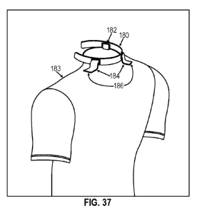
[0094] FIG. 37 is an illustration a system in which the collar shown in
FIG. 35 is
secured to a shirt shown in FIG. 36 and in which the straps are aligned with
the holes when the
collar is properly positioned about the neck of the subject. The straps on the
shirt pass through
the holes in the collar and are fastened to the body of the shirt in order to
secure the collar to the
shirt.
[0095] FIG. 38 illustrates another embodiment of the system in which the
straps are
adapted to pass over the collar and are fastened to the body of the shirt. The
collar in this system
is illustrated as lacking holes adapted to receive the straps; however, the
system may be effected
using any suitably designed collar, including a collar containing holes (but
in which the holes are
not used or are not aligned with the straps when the collar is properly
positioned about the neck
of the subject).
[0096] The drawings are described in greater detail in the description and
examples
below.
DETAILED DESCRIPTION
[0097] The details of some exemplary embodiments of the methods and
systems of the
present disclosure are set forth in the description below. Other features,
objects, and advantages
of the disclosure will be apparent to one of skill in the art upon examination
of the following
description, drawings, examples and claims. It is intended that all such
additional systems,
methods, features, and advantages be included within this description, be
within the scope of the
present disclosure, and be protected by the accompanying claims.
[0098] Before the present disclosure is described in greater detail, it is
to be understood
that this disclosure is not limited to particular embodiments described, and
as such may, of
course, vary. It is also to be understood that the terminology used herein is
for the purpose of
-18-
CA 02953130 2016-12-20
WO 2015/200672 PCT/US2015/037753
describing particular embodiments only, and is not intended to be limiting,
since the scope of the
present disclosure will be limited only by the appended claims.
[0099] When liquid in a tank or vessel experiences dynamic motion, a
variety of wave
interactions and liquid phenomena can exist. The oscillation of a fluid caused
by external force,
termed "sloshing", occurs in moving vessels containing liquid masses. This
sloshing effect can
be a severe problem in energy absorption, and thus, vehicle stability and
control. The present
disclosure encompasses methods and apparatus for reducing SLOSH effects in
living creatures,
and in particular in the intracranial and spinal regions of the animal or
human subject.
[00100] The mitigation of blast wave and collision damage is based largely
on the
principle of energy absorption of fluid-filled containers. As there becomes
more room for
movement of fluid within a vessel, more energy can be absorbed (SLOSH) rather
than
transmitted through the vessel. To reduce this energy absorption, one must
attempt to more
closely approximate elastic collisions. Elastic collisions are those that
result in no net transfer of
energy, chiefly, acoustic, kinetic, vibrational, or thermal (also stated as a
coefficient of restitution
(r) approximating 1.0). Various embodiments described below may locally alter,
elevate, or
temporarily maintain an altered physiology of an organism to reduce the
likelihood of energy
absorption through SLOSH whereby the coefficient of restitution (r) is
increased. The
coefficient of restitution (r) indicates the variance of an impacting object
away from being a
complete total elastic collision (an (r) of 1.0 = no energy transfer). Blast
or energy absorption in
an organism can be viewed as a collision of bodies and thus be defined by a
transfer of energies
through elastic or inelastic collisions. The mechanisms for biological fluids
and molecules to
absorb energy can thus be identified and the resultant means to mitigate that
absorption can be
achieved through several SLOSH reducing techniques. Dissipation of energies
post blast is also
potentiated through these techniques.
[00101] SLOSH absorption may be reduced by reversibly increasing pressure
or volume
within the organs or cells of the organism. Applying this concept to the
contents of the skull, the
intracranial volume and pressure can be reversibly increased by a device that
reduces the flow of
one or more of the cranial outflow vessels. One embodiment of such a device
would compress
-19-
CA 02953130 2016-12-20
WO 2015/200672 PCT/US2015/037753
the outflow vessels enough to cause an increase in venous resistance, yet not
enough to increase
an arterial pressure leading into the cranium above approximately 80 mm Hg.
[00102] Mitigating SLOSH by increasing the pressure of the fluid contents
of the brain
can significantly reduce the propensity for damage to the brain tissue or its
blood vessels by
reducing the compressibility of the brain. The reduction in compressibility
results in reduced
absorption of kinetic, acoustic, thermal, and vibrational energy by the brain.
[00103] Intracranial volume can also be reversibly increased by increasing
the pCO2 in the
arterial blood or by the delivery of one or more medicaments to facilitate an
increase in
intracranial volume or pressure including but not limited to Minocycline,
insulin-like growth
factor 1, Provera, and Vitamin A. Such techniques may be used in combination
with use of the
devices disclosed herein.
[00104] With respect to the inner ear, it is known that the cochlear
aqueduct is in direct
communication with the cerebrospinal fluid (CSF) and the vein of the aqueduct
drains directly
into the internal jugular vein (IJV). The venous blood empties either directly
into the inferior
petrosal sinus or internal jugular vein, or travels through other venous
sinuses via the vein of the
vestibular or cochlear aqueduct. Reduced outflow of the internal jugular would
necessarily
congest the cochlear vein and take up the compliance of the inner ear, thereby
improving elastic
collisions at the macroscopic, cellular, and molecular level and, thus,
reducing energy
impartation into these structures.
[00105] Approximately 30 ml (21%) of a total CSF volume of 140 ml resides
within the
spinal axis, and about one-third of the compliance of the CSF system has been
attributed to the
spinal compartment. As in the brain, increasing the pressure and volume of the
CSF within the
spinal compartment reduces the susceptibility of the spinal compartment to
concussive injuries
by increasing the elasticity of the contents of the spinal column, thereby
reducing the amount of
energy absorbed by the contents of the spinal column when subjected to a
concussive force.
[00106] With respect to ocular injuries, it is known that the woodpecker
has a "pectin
apparatus" that protects the globe of its eyeball from the 1200G impact of
pecking. The sole
purpose of the pectin apparatus appears to be to increase the volume and
pressure of the vitreous
-20-
CA 02953130 2016-12-20
WO 2015/200672
PCT/US2015/037753
humor inside the eyeball. The pectin apparatus is situated within the eyeball
and fills with blood
to briefly elevate intraocular pressure, thereby maintaining firm pressure on
the lens and retina to
prevent damage that might otherwise occur during the 80 million pecking blows
over the average
woodpecker's lifetime. While humans lack the pectin apparatus, it is possible
to increase
intraocular pressure by externally applying pressure on the external jugular
veins (EJV).
[00107] One
aspect of the present invention, therefore, encompasses a device that raises
intracranial volume and pressure and/or intraocular pressure when worn by a
subject animal or
human. The device is configured to apply pressure to the outflow vasculature
in the neck (e.g.,
one or more internal and/or external jugular vein), thus increasing
intracranial and/or intraocular
pressures and volumes in the wearer. In doing so, the device reduces energy
absorption by the
wearer due to concussive effects, thus reducing the likelihood of one or more
of brain, spine, and
eye damage from a concussive event. Devices of the instant invention could be
worn preferably
before, in anticipation of and during events with SLOSH and traumatic brain
injury risks.
[00108]
Safely and reversibly increasing cerebral blood volume by any amount up to 10
cm3 and pressure by any amount up to 70 mmHg would serve to fill up the
compliance of the
cerebral vascular tree and thus reduce the ability to absorb external energies
through SLOSH
energy absorption. With the application of measured pressure to the neck, the
cranial blood
volume increases rapidly and plateaus at a new higher level. Moyer et al
reported that cerebral
arterial blood flow was not affected by obstructing the venous outflow of
blood from the brain.
The blood volume venous pressure relationship shows a diminishing increase in
volume with
each increment of neck pressure over the range 40 to 70 mm of mercury. It is
of interest that the
cranial blood volume increases from 10 to 30 per cent (with this neck
pressure). Similarly, CSF
pressure also increases upon compression of the individual jugular veins.
Under the same neck
pressure, the average rise in CSF pressure is about 48%. These changes occur
very rapidly upon
initiation of pressure; jugular compression increases cerebral blood flow to a
new plateau in as
little as 0.5 seconds. Although lesser cranial pressure and volume increases
may still have
beneficial effects, it is intended that devices of the instant invention
increase cranial blood
volume by at least 3cm3 through an application of at least 5 mm Hg neck
pressure.
-21-
CA 02953130 2016-12-20
WO 2015/200672 PCT/US2015/037753
[00109] Devices of the present invention, therefore, may take many forms,
but share the
functional feature of constantly or intermittently applying pressure to one or
more veins in the
neck (specifically, but not limited to the internal and external jugular
veins, the vertebral veins,
and the cerebral spinal circulation, and most preferably, the interior jugular
vein) to restrict blood
flow exiting the brain. Thus, the instant devices include at least one
inwardly directed
protuberance that is inwardly directed and contacts the neck of the wearer of
the device, and at
least one means for applying pressure to the one or more protuberances such
that the
protuberances apply pressure to one or more veins in the neck, thereby
restricting blood flow
exiting the brain.
Inwardly Directed Protuberances That Contact the Neck of the Wearer
[00110] In some embodiments, the one or more inwardly directed
protuberances are
integral to the component of the device responsible for applying pressure to
the neck. In
alternative embodiments, the one or more inwardly directed protuberances are
distinct from the
component of the device responsible for applying pressure to the neck. Is to
be generally
understood that the protuberances may be any suitable shape, e.g., pointed or
round, and
comprising of any suitable material, such as defined by a rigid or semi-rigid
plastic body, a
thickened region of a collar, and the like.
[00111] In some embodiments, the protuberances may substantially be defined
by a
bladder, whereby pressure is exerted on the neck of the wearer when the
bladder is inflated or
filled. In some related embodiments, the bladder may contain reversibly
compressible foam that
is in fluid communication with the external atmosphere. In further related
embodiments, the
interior of the bladder is in fluid communication with the external atmosphere
via a pressure
release valve. In embodiments comprising a bladder, foam, and valve, these
components may be
configured so that the foam expands within the bladder, drawing air into the
bladder through the
pressure valve to inflate the bladder to a desired pressure. However, the
pressure release valve
may be configured to allow for release of air from the bladder upon an
application of pressure to
the device that may otherwise raise the amount of pressure applied to the neck
to an
uncomfortable or undesirable level. In other embodiments, the bladder may
contain a gas or
liquid and may be outfitted or configured to interface with a pump mechanism
such that the
-22-
CA 02953130 2016-12-20
WO 2015/200672 PCT/US2015/037753
pressure of the bladder may be user adjusted. The pump mechanism may be any
suitable pump
mechanism as would be understood in the art, such as e.g., a powered pump, or
a hand-
compressible pump whereby a liquid, air or a gas can be applied to the
bladder. In certain
embodiments the device may further comprise a pressure sensor operably linked
to the pump
mechanism or bladder whereby the degree of inflation may be regulated as to
the extent and
duration of the pressure applied to an underlying neck vein.
[00112] In some embodiments, the protuberance comprises a spring or
resilient
compressible material. In these embodiments, the spring or resilient
compressible material is
disposed within the protuberance such that application of the protuberance to
the neck at least
partially compresses the spring or resilient compressible material. The force
exerted by the at
least partially compressed spring or resilient compressible material ensures
that the protuberance
maintains a desired pressure on the neck.
[00113] In some embodiments, the device may comprise a resilient arcuate
band having a
general C, V, or U-shape. The band may be formed of a resilient spring-like
material whereby
the C, V, or U-shaped band is forced open as the device is applied. After
application of the
device, spring tension causes compression of the band, resulting in the mid-
point or bend-point
of the band to extend toward and apply pressure to the neck. Thus, in these
embodiments, the
mid-point or bend-point of the bands are the protuberances that contact the
neck of the wearer.
[00114] In some embodiments, at least a portion of an inwardly directed
surface of the one
or more protuberances may be coated with a suitable adhesive to facilitate
placement of the
protuberances on the neck, and prevent movement of the protuberance once in
place.
Additionally or in the alternative, in embodiments where the protuberances are
distinct from the
component of the device which applies pressure to the neck, at least a portion
of an outwardly
directed surface of the one or more protuberances may be coated with a
suitable adhesive. In
such embodiments, the design of the device may such that a protuberance may be
paced between
a component which applies pressure to the neck and the neck itself An
outwardly directed
surface of the protuberance would then contact an inwardly directed surface of
the pressure-
providing component of the device such that the adhesive on the outwardly
directed surface of
the protuberance would prevent movement of the protuberance once in place.
-23-
CA 02953130 2016-12-20
WO 2015/200672 PCT/US2015/037753
[00115] One exemplary embodiment of this type (discussed in greater detail
below)
comprises three pieces: two round or oval plastic protuberances (one for
application to either
side of the neck) and an elastic collar. The device could be applied by first
putting the collar
around the neck, and then by placing the plastic protuberances between the
collar and the neck at
the appropriate locations so as to apply pressure to the internal jugular vein
on either side of the
neck. As will be appreciated for this example, a mild adhesive coating on the
inwardly directed
and/or outwardly directed surfaces of the protuberances will assist in
preventing movement of
the protuberances once they are installed between the collar and the neck.
Alternately, if the
protuberances have an adhesive coating of sufficient strength at least on the
inwardly directed
surfaces, the protuberances may be placed on the appropriate locations on the
neck prior to
installation of the collar. In either case, the collar applies pressure to the
protuberances, which in
turn applies pressure to the neck veins.
[00116] In other embodiments of this type, two protuberances may be secured
to one
another with a tether of the appropriate length to act as an alignment and
spacing guide for
application on either side of the neck. In some embodiments, the tether may be
removable, so
that once the protuberances are applied to the neck, the tether may be pulled
or otherwise
removed, leaving the protuberances in place on the neck of the wearer.
[00117] In some embodiments, the protuberances are compressible pads or
solid forms
sized to apply pressure substantially only to the internal jugular vein.
Circumferential and Semi-Circumferential Collar Type Devices
[00118] In some embodiments, the device may be a circumferential or semi-
circumferential collar. A circumferential collar is a collar that encircles
the entire circumference
of the neck when the device is worn by an animal or human subject. A semi-
circumferential
collar is a collar that encircles a majority of the circumference of the neck
when the device is
worn by an animal or human subject. The portion of the circumference of the
neck that is not
encircled by a semi-circumferential collar may be disposed at any location
around the
circumference of the neck, so long as the encircled portion allows for
application of pressure on
inwardly directed protuberances specifically located in order to restrict
blood flow exiting the
brain. Typically, the open portion will be either located at the front of the
throat (e.g., in some
-24-
CA 02953130 2016-12-20
WO 2015/200672 PCT/US2015/037753
embodiments, a semi-circumferential collar may encircle the neck except an
area substantially
defined by laryngeal prominence, also known as the "Adam's apple"), or located
at the back of
the neck.
[00119] In embodiments where the device comprises a circumferential collar,
it is
contemplated that the applied pressure to the neck may be due to an internal
dimension of the
collar being less than the neck diameter. This difference in internal
dimension of the collar may
be achieved by any number of configurations dictated by the materials used to
construct the
collar. For instance, in a collar comprising inelastic materials, the collar
may be sized to apply
the appropriate pressure when worn by an individual. In these embodiments, the
size of the
collar may be such that the collar is tailored to an individual and thus
requires no adjustment for
fit. Alternatively, the size of the collar may be adjustable by any of a
number of means, some of
which are discussed further below. In some embodiments, the collar may
comprise an elastic
material such that the internal dimension of the elastic collar is expanded
when the collar is
worn, and the collar applies pressure to the neck of the wearer as a result of
compressive force
exerted by the expanded elastic material. Elastic materials may also confer
the benefit of
increased comfort for the wearer.
[00120] In embodiments where the device comprises a semi-circumferential
collar, it is
contemplated that the collar comprises a resilient arcuate band having a
general C, V, or U-
shape. In these embodiments, it is intended that the band extend a majority,
if not the entirety, of
the length of the collar. In these embodiments, the collar thus semi-rigidly
defines a C, V, or U-
shape that is expanded as the collar is applied to the neck of a wearer.
Spring tension from the
expanded resilient arcuate band causes a compressive force that keeps the
collar in place on the
neck and applies the intended pressure to the neck veins.
[00121] In these embodiments, at least one inwardly directed pad or form
may be disposed
at appropriate locations on opposing sides of the collar, such that the
inwardly directed pads or
forms are configured to contact the neck and apply pressure to a point above
the interior jugular
vein. In embodiments where the semi-circumferential collar is open at the
front of the throat, the
area of the neck not covered by the semi-circumferential collar may define a
region
approximating the laryngeal prominence, also known as the "Adam's apple." In
these
-25-
CA 02953130 2016-12-20
WO 2015/200672 PCT/US2015/037753
embodiments, the inwardly directed pad or forms disposed on opposing sides of
the collar may
be located at or near the terminal ends of the resilient arcuate band. In
embodiments where the
semi-circumferential collar is open at the back of the neck, the inwardly
directed pads or forms
may not be disposed near the terminal ends, but rather may be disposed much
closer to the mid-
point of the band.
[00122] In some embodiments where the device comprises a circumferential
collar or a
semi-circumferential collar that is open at the back of the neck, the device
may comprise a
laryngeal bridge that defines a cut-out at the front of the neck. The size and
shape of the
laryngeal bridge may be configured so as to minimize contact of the collar
with the laryngeal
prominence in order to make the collar more comfortable for the wearer. In
these embodiments,
the laryngeal bridge may be of any suitable material as to provide a rigid or
semi-rigid
continuation of the collar around the front of the neck. In some embodiments,
the laryngeal
bridge may comprise thick or reinforced textile material, plastic, metal, or
any combination
thereof
[00123] In some embodiments where the device comprises a circumferential
collar, the
device comprises two components: a front section comprising the one or more
inwardly directed
protuberances and a laryngeal bridge, and a back section comprising a length
of fabric
configured to be removably attached at either end to corresponding ends of the
front section. In
some embodiments, the length of fabric comprises an elastic material;
alternatively, the length of
fabric may comprise an inelastic fabric. Removable attachment of either end of
the front section
to the corresponding end of the back section may be by any suitable method
known in the art,
such as a hook and ladder attachment, a hook and loop attachment, a snap, a
button, a chemical
adhesive, or any of a number of attachment mechanisms that would be known to
one skilled in
the art. A device with removable attachment means could also have a breakaway
release
mechanism whereby the device can break open or apart at a predetermined force
to prevent the
device from inadvertently being snagged or compressing too tightly.
[00124] Many of the devices described herein are described as potentially
comprising an
elastic material. More particularly, it is intended that these devices may
comprise materials that
are elastically elongatable around the circumference of a subject's neck.
Elastic materials can be
-26-
CA 02953130 2016-12-20
WO 2015/200672 PCT/US2015/037753
any material which when stretched will attempt to return to the natural state.
Exemplary
materials may include one or more of textiles, films (wovens, non-wovens and
nettings), foams
and rubber (synthetics and natural), polychloroprene (e.g. NEOPRENE:),
elastane and other
polyurethane- polyurea copolymerss (e.g. SPANDEX , LYCRA ), fleece, warp knits
or narrow
elastic fabrics, raschel, tricot, milanese knits, satin, twill, nylon, cotton
tweed, yarns, rayon,
polyester, leather, canvas, polyurethane, rubberized materials, elastomers,
and vinyl. There are
also a number of elastic materials which are breathable or moisture wicking
which may be
preferable during extended wearing periods or wearing during periods of
exercise. As indicated
above, elastic materials may confer the benefit of increased comfort for the
wearer by providing
sufficient compressive pressure, yet remaining flexible to accommodate a full
range of motion
and/or muscle flex in the wearer.
[00125] In addition, a device constructed with an elastic material may be
partially
reinforced, coated, or otherwise include one or more protecting materials such
as Kevlar0 (para-
aramid synthetic fibers), Dyneema0 (ultra-high-molecular-weight polyethylene),
ceramics, or
shear thickening fluids. Such reinforced materials may confer the benefit of
increasing the
devices resistance to lacerations. As such, reinforced devices may provide the
user the added
benefit of protecting the neck from damage from lacerations.
[00126] In some embodiments, circumferential or semi-circumferential
collars may be
constructed with materials, elastic or otherwise, that are fire resistant.
[00127] The device may encompass horizontally, the entire neck or just
partially up and
down the neck. The width of the devices described herein may range from a mere
thread (at a
fraction of an inch) to the length of the exposed neck (up to 12 inches in
humans or greater in
other creatures), the length may range from 6 to 36 inches to circumnavigate
the neck. The
width of the compression device could be as small as 1/4 inch but limited only
by the height of
the neck in largest width, which would be typically less than 6 inches. The
thickness of said
device could range from a film being only a fraction of a millimeter to a
maximum of that which
might be cumbersome yet keeps ones neck warm, such as 2-3 inches thick.
[00128] One embodiment of the device may be pre-formed for the user in a
circular
construct. This one size fits all style can have a cinch of sorts that allows
one to conform the
-27-
CA 02953130 2016-12-20
WO 2015/200672 PCT/US2015/037753
device to any neck size. Alternatively the device may have a first end and a
second end which
are connected by a fastener. A fastener may be magnetic, a tack strip, a hook
and ladder
attachment, a hook and loop attachment, a ply strip, one or more slide
fasteners, one or more
zippers, one or more snaps, one or more buttons, one or more safety pin type
clasp mechanisms,
overlapping electrostatic contact materials, or any of a number of attachment
mechanisms that
would be known to one skilled in the art. A device with a fastener could have
a breakaway
release mechanism whereby the device can break open or apart at a
predetermined force to
prevent the collar from inadvertently being snagged or compressing too
tightly. One quick
release or automatic release embodiment would be the applying of small amounts
of hook and
ladder attachments within a circumferential ring which would shear apart upon
too much force
being applied to the device.
[00129] Another embodiment of the device could fasten such that the user
would be able
to pull one end of the collar (like a choker collar for a dog) and the force
exerted by the user
effectually decreases the length or circumference of the device. When the
desired neck
compression is no longer needed (such as between football plays) the user
could then release the
compression by a second gentle tug or by a separate release mechanism also
positioned on the
device.
[00130] Other fit adjustment systems may be used in the collar-type devices
described
herein. For example, in one embodiment, a pull-away cable-tie (e.g., Zip-tie )
type ratcheting
fit adjustment system may be included. This type of system may include one or
more pull-away
cable-ties configured to release from the collar when pulled at or above a
specific pressure, thus
ensuring that the collar is not over tightened. In alternate embodiments, a
rotating ratcheting fit
adjustment system may be included. In such embodiments, system may be designed
such that an
external tool is employed fit adjustment. Preferably, such systems utilize
elastic materials and or
an adjustable fastener system (as described above) such as a Velcro closure-
system to provide
a gross-fit of the device. The ratcheting adjustment system would then be used
for fine-
adjustments of the device specific for an individual wearer. As an alternative
to an external tool
system, rotating ratchet fit adjustment systems which include an integrated
adjustment dial, e.g.,
a BOAC) rotating ratchet fit adjustment system as described in U.S. Pat. No.
8,381,362 and U.S.
Pat. Pub. No. 2012/0246974.
-28-
CA 02953130 2016-12-20
WO 2015/200672 PCT/US2015/037753
[00131] In some embodiments, a circumferential or semi-circumferential
collar may
comprise a shape memory polymer. In such embodiments, the collar would be
applied to the
neck of a user and then the appropriate stimulus would be applied to the shape
memory polymer,
causing the collar to shrink to fit.
[00132] In some embodiments, a circumferential or semi-circumferential
collar may
comprise a bladder whereby the pressure exerted on the neck of the wearer by
the collar may be
adjusted by inflating or deflating the bladder. In some related embodiments,
the bladder may
contain reversibly compressible foam that is in fluid communication with the
external
atmosphere. In further related embodiments, the interior of the bladder is in
fluid
communication with the external atmosphere via a pressure release valve. In
embodiments
comprising a bladder, foam, and valve, these components may be configured so
that the foam
expands within the bladder, drawing air into the bladder through the pressure
valve to inflate the
bladder to a desired pressure. However, the pressure release valve may be
configured to allow
for release of air from the bladder upon an application of pressure to a
protuberance that may
otherwise raise the amount of pressure applied to the neck to an uncomfortable
or undesirable
level. In other embodiments, the bladder may contain a gas or liquid and may
be outfitted or
configured to interface with a pump mechanism such that the pressure of the
bladder may be user
adjusted. The pump mechanism may be any suitable pump mechanism as would be
understood
in the art, such as e.g., a powered pump, or a hand-compressible pump whereby
a liquid, air or a
gas can be applied to the bladder. In certain embodiments the device may
further comprise a
pressure sensor operably linked to the pump mechanism or bladder whereby the
degree of
inflation may be regulated as to the extent and duration of the pressure
applied to an underlying
neck vein. In some embodiments, the bladder is disposed to at least include a
portion of the
collar other than above a protuberance. In some embodiments, the bladder is
disposed through a
majority of the circumference of the collar.
[00133] In some embodiments, a circumferential or semi-circumferential
collar may
further comprise a pouch or pocket. This pouch or pocket may be externally
accessible, i.e.,
accessible while the collar is being worn, or only accessible when the collar
is removed. The
dimensions of such a pouch or pocket may be such that the pouch or pocket is
suitable to carry
-29-
CA 02953130 2016-12-20
WO 2015/200672 PCT/US2015/037753
one or more items useful for the treatment of TBI related calamities, such as
a material enabling
CO2 delivery, carbonic anhydrase tablets, methylene blue, DHA, smelling salts,
etc.
[00134] In some embodiments, a circumferential or semi-circumferential
collar may
further comprise an electrical circuit comprising a piezoelectric heat pump
configured to alter the
temperature of the inwardly directed surface of the collar. Such a heat pump
may be used to
either heat or cool the device, for example by as much as 70 from ambient
temperature.
[00135] In some embodiments, a circumferential or semi-circumferential
collar may
further comprise an electrical circuit configured to provide a therapeutic
electrical stimulation to
the neck of the wearer. For example, an electrical circuit may be configured
to provide
transcutaneous electrical nerve stimulation.
Non-Collar Type Devices
[00136] In some embodiments, the device may be a non-collar type device.
Non-collar
type devices are those that cover or encircle a minority of the circumference
of the neck when
the device is worn by an animal or human subject. However, the portion of the
circumference of
the neck that is covered or encircled by non-collar type devices must at least
include one or more
areas of the neck above a neck vein, as described above. As with collar-type
devices, non-collar
type devices also utilize inwardly directed protuberances to apply pressure to
the neck at specific
locations in order to restrict blood flow exiting the brain. Any of the
protuberances described
above may find use in non-collar type devices.
[00137] In some embodiments, the externally directed side of a protuberance
may be
covered by flexible material that extends beyond the area defined by the
protuberance. In these
embodiments, at least a portion of this extended inwardly directed surface
contacts the neck
when the device is in place. In some embodiments, the at least a portion of
the inwardly directed
surface of the flexible material that contacts the neck is coated with an
appropriate adhesive,
such that when applied to the neck, the flexible material holds the
protuberance in an appropriate
position and applies pressure to a neck vein. The flexible material may be
elastic or non-elastic.
The flexible material may be any suitable synthetic or natural woven or
textile material, or any
suitable plastic.
-30-
CA 02953130 2016-12-20
WO 2015/200672 PCT/US2015/037753
[00138] Such embodiments may comprise a pair of material/protuberance
combinations
for application to both sides of the neck. Some related embodiments may
comprise a pair of
material/protuberance combinations joined by a tether, as described above. The
tether may be of
appropriate length so as to serve as an aid to alignment and proper placement
of the
protuberances at the correct locations on the neck. In some embodiments, the
tether may be
removably attached to the pair of material/protuberance combinations so that
after placement of
the protuberances on either side of the neck, the tether is removed.
[00139] In some non-collar type devices, the device may comprise a
resilient arcuate band
having a general C, V, or U-shape. In these embodiments, it is intended that a
protuberance is
located at or near the terminus of each arm of the band, and that when the
device is in place, the
band extends around the front of the neck. In these embodiments, the band thus
semi-rigidly
defines a C, V, or U-shape that is expanded as the device is applied to the
neck of a wearer.
Spring tension from the expanded resilient arcuate band causes a compressive
force that keeps
the device in place on the neck and applies the intended pressure to the neck
veins via the
protuberances. In some embodiments, the resilient arcuate band is sized and
shaped such that it
does not cross the front of the neck in the general area of the laryngeal
prominence. Instead, the
band may cross the front of the neck at a position below the laryngeal
prominence.
Garments or Other Protective Gear Comprising Integral Protuberances
[00140] In yet other embodiments, it is envisioned that protuberances (as
described above)
may be incorporated into various articles of clothing and/or other protective
gear. Such garments
and/or other protective gear typically may be designed for specific purposes,
e.g., as part of a
military uniform, sporting apparel, neck guard for first responders, flame
retardant head gear for
automobile or motorcycle drivers or firefighters, etc. In any case,
protuberances may be
included at the appropriate positions in a portion of a garment or protective
gear that contacts the
neck of the wearer, i.e., the collar, with the collar providing compressive
force on the
protuberances. As such, any of the closing, alignment, or fitting means, or
any other optional
feature provided in regards to circumferential or semi-circumferential collar-
type devices may be
incorporated in garment and/or protective gear embodiments.
-31-
CA 02953130 2016-12-20
WO 2015/200672 PCT/US2015/037753
[00141] In one aspect, the invention provides a system having a garment and
a
circumferential or semi-circumferential collar, each adapted for use with the
other. In one
embodiment, the garment has a top portion adapted to receive the collar. For
example, the top
portion of the garment may have an extended flap which is designed to provide
a layer of fabric
between the subject's neck and the collar, wherein the extended portion of
that flap is folded
over, and optionally fastened, to conceal the collar and help hold the collar
in place. In another
embodiment, the top portion of the garment has a sleeve which is adapted to
receive the collar.
In another embodiment, the collar is place directly against the subject's skin
and the top portion
of the garment is adapted to conceal all or part of the collar. Optionally,
the inside of the
garment and the outside of the collar have a mutually engaging fastening means
in order to hold
the top portion of the garment in place against the collar. One such suitable
fastening means is a
hook-and-pile system (e.g., VELCRO ).
[00142] In another aspect, the top portion of the garment has integral
protuberances
permanently affixed therein. Optionally, the top portion of the garment
comprises a rigid or
semi-rigid member, similar to the stand-alone collar, adapted to apply neck
vein pressure via the
protuberances. Alternatively or in addition to the rigid member, the top
portion of the garment
may be fully circumferential with a closing and/or fitting mechanism adapted
to apply and
control neck vein pressure via the protuberances.
Visual or Tactile Alignment Aids
[00143] Any of the embodiments described above may further comprise one or
more
materials, and/or apply one or more construction methods, designed to provide
the user or a 3rd
party observer with a visual or tactile aid in determining proper alignment
and positioning of the
protuberances. For instance, a collar type device may include a small strip or
patch of a
contrasting or reflective material, or a material with a different texture, at
the mid-point of the
neck. Alternatively or in addition, similar visual or tactile cues may be
incorporated into any of
the above devices so as to provide an outward indication of the location of a
protuberance.
[00144] Further, any of the embodiments described above that utilize
elastic materials may
comprise a dual layered elastic material that exposes a change in graphic or
color when
sufficiently stretched to apply an appropriate force on an underlying
protuberance. In such
-32-
CA 02953130 2016-12-20
WO 2015/200672 PCT/US2015/037753
embodiments, the change in graphic or color may provide a visual cue to the
wearer or 3rd party
observer that the device is applying at least sufficient compressive force.
Incorporated Sensors or Other Electronic Systems
[00145] Any of the above devices may also have one or more monitoring,
recording,
and/or communicating devices attached or embedded. For example, the device may
comprise a
sensor capable of detecting one or more environmental parameters around the
wearer, one or
more physiological parameters of the wearer, or some combination thereof
Exemplary
environmental parameters that may be detected include time the collar has been
worn, barometric
pressure, ambient temperature, humidity, acceleration/decelration (i.e., G
forces), positionality
(upright/supine), etc. Physiological parameters that may be detected include
pulse, blood
pressure, plethysmography, dermal temperature, oxygen saturation,
carboxyhemoglobin level,
methemoglobin level, blood sugar, electrical flow, etc. of the human or animal
wearing the
device. Any of such sensors may be used to monitor some environmental or
physiological
characteristic or performance aspect of the wearer. Sensors capable of
detecting pulse, blood
pressure, and/or plethysmography may serve the additional or alternate purpose
of being used as
an alignment and/or fit aid, notifying the user when the protuberance is
properly placed over a
neck vein and is exerting an appropriate pressure so as to restrict blood
flow.
[00146] In some related embodiments, a device may further comprise an
electronic circuit
capable of providing visual, auditory, or tactile indicia of malfunction, or
an undesirable sensor
reading. For instance, an electronic circuit may be configured to vibrate the
collar when a pulse
or blood pressure sensor detects a reading that is either higher or lower than
a predetermined
value.
[00147] Additionally or in the alternative, any of the above devices may
comprise an
electronic circuit configured to transmit the location of the wearer. For
instance, any of the
above devices may comprise an electronic circuit configured to transmit the
GPS coordinates of
the wearer for tracking the location of the wearer, or for search and rescue
purposes.
-33-
CA 02953130 2016-12-20
WO 2015/200672 PCT/US2015/037753
[00148] Additionally or in the alternative, any of the above devices may
comprise an
electronic circuit configured to transmit and/or receive voice communications
between the
wearer and a third party.
[00149] In some embodiments, the output of such a sensor may be visually or
audibly
communicated to the user or a 3rd party by another component of the device,
e.g., an electronic
circuit configured to provide a visual or auditory indication (such as with an
LED, piezoelectric
speaker, etc.). In some embodiments, the device further comprises a
communication means such
that a signal from the sensor may be communicated to an external electronic
device, such as a
smartphone, laptop, or dedicated receiver.
[00150] These terms and specifications, including the examples, serve to
describe the
invention by example and not to limit the invention. It is expected that
others will perceive
differences, which, while differing from the forgoing, do not depart from the
scope of the
invention herein described and claimed. In particular, any of the functional
elements described
herein may be replaced by any other known element having an equivalent
function.
Exemplary Embodiments
[00151] Particular embodiments of a collar type device are illustrated in
FIGS. 1-3.
Referring to FIGS. 1(a)-(c), a compression collar 10 includes an elongated
strap 12 that may be
provided in various sizes to encircle the neck of the animal or human subject.
In one specific
embodiment the strap may be provided in standard lengths of 14, 16 and 18
inches to fit the
normal range of neck sizes for humans. The width in a specific example may be
about 1.5 inches
to fit within the anatomy of the neck below the laryngeal prominence. To
minimize the
prominence of the collar, the strap may have a thickness of about 0.12 inches.
The strap 12 may
be formed of a woven, breathable, dermatologically inert and non-irritating
material, such as
cotton or certain polyesters. Since the strap is intended to apply consistent
pressure to the
jugular vein of the subject the strap material is preferably generally
elastic, but formed of an
elastic material that will not permanently stretch appreciably over time. It
can be appreciated
that stretching the material so that the neutral length of the strap is longer
than its original
condition can render the strap 12 useless. On the other hand, the strap
material must be
sufficiently elastic or elastically elongatable to remain comfortable when
worn for a long period
-34-
CA 02953130 2016-12-20
WO 2015/200672 PCT/US2015/037753
of time, and to flex appropriately with the muscles of the neck. The effective
length of the strap
12 is made adjustable by the addition of adjustable engagement elements 16 and
18 at opposite
ends of the strap. For instance, in the embodiment shown in FIG. 1(a) the
latch element 16
defines a serrated channel 16a that receives the resilient prongs 18a of the
other element. The
prongs 18a are biased to provide an outward force against the channel 16a of
the latch to hold
the prongs at the location of a particular serration 16b. In the illustrated
embodiment, seven
serrations are depicted which provide seven locations for engagement of the
prongs 18a for fine
adjustment of the length of the collar. The two components 16, 18 may be sewn
onto the strap
12 or permanently affixed in a conventional manner sufficient so that the
engagement elements
will not pull free from the strap during use.
[00152] Two versions of the collar are depicted in FIGS. 1(a) and 1(b). The
version of
FIG. 1(a) is provided for a male human and includes a cut-out 14 at the
location of the laryngeal
prominence. The strap 12 of FIG. 1(b) does not include the cut-out and may be
typically
provided for female human subjects. The cut-out may have a width of about 1.5
inches and a
depth of about 0.5 inches to accommodate the typical laryngeal prominence. It
can be
appreciated that the collar 10 is engaged around the neck of the subject so
that the cut-out 14 is
below and sufficiently clear of the prominence to avoid any discomfort to the
subject.
[00153] In a further feature of the collars 10, 10', a pair of compressible
pads 20 are
provided spaced apart across the midline of the strap 12, 12'. The pads are
sized and located to
bear against the neck at the location of the jugular veins. In one embodiment
the pads are spaced
apart by about 2.5 inches, have a width/length dimension of1.0-1.5 inches and
a thickness of
about 0.04 inches. As shown in FIG. 1(c) the pads may be partially embedded
within the strap
12. The pads 20 may be formed of a breathable foam that exhibits good recovery
from
compression. The pads may be formed of a material capable of exerting
compression of 5-30
mm Hg when the collar is worn, such as a flexible polyurethane foam.
[00154] Additional embodiments of the compression collar are shown in FIGS.
2 and 3
that incorporate different engagement elements. For instance, the collar 30 of
FIG. 2
incorporates an array of snap pairs 36 at one end that engage a pair of snaps
38 at the opposite
end. The snap pairs 36 may be spaced at pre-determined intervals, such as at
1/4 inch spacings to
-35-
CA 02953130 2016-12-20
WO 2015/200672 PCT/US2015/037753
permit adjustment of the collar diameter when worn. The collar 50 in FIG. 3
incorporates a row
of hooks 56 at one end that engage a corresponding row of loops 58 at the
opposite end. The
embodiment of FIG. 3 illustrates that the engagement elements need not be
adjustable, although
adjustability is preferred. In the embodiment of FIG. 3 this adjustability may
be accomplished
by a VELCRO type connection between the strap 52 and the row of loops 58. In
particular, a
VELCRO type pad interface 59 may be used to mount the loops 58 to the strap
at different
positions along the length of the strap. In a further alternative, the VELCRO
interface may be
between the two ends with mating VELCRO type pads on each end.
[00155] In one aspect of the compression collars disclosed herein, the
engagement
elements are preferably configured to break loose or disconnect at a certain
load, to avoid the
risk of choking or damaging the subject's neck and throat if the collar is
snagged or grabbed.
Thus, the engagement elements 16, 18 of FIG. 1, the snaps 36, 38 of FIG. 2 and
the hook
attachment 59 of FIG. 3 can be calibrated to disconnect when the collar is
pulled with sufficient
force. In a further embodiment, the engagement elements, such as snaps 36, 38,
may be replaced
by magnets or a magnet array. The magnets are strong enough to maintain the
desired pressure
on the jugular veins when the collar is in use. The magnet strength may be
calibrated to break
loose at a certain load. The break-away feature may also be integrated into
the strap apart from
the engagement elements. For instance, the strap may incorporate a region
between a pad 20 and
an engagement element that has a reduced strength so that the strap tears
under a certain load.
Alternatively, a non-adjustable engagement may be provided in this region
calibrated to
disengage at a predetermined load.
[00156] In the embodiments of FIGS. 1 and 3, the jugular vein is compressed
by the pad
20. The pad has a predetermined thickness and compressibility. In an
alternative embodiment,
the pads are replaced by inflatable bladders 40, as shown in FIG. 2. In this
embodiment a fluid
line 46 connects the bladders to a pump 42 and a release valve 44. The pump 42
can be of the
type that is manually squeezed to draw atmospheric air into the bladders. A
one-way valve 43 is
provided in the fluid line 46 at the pump 42 to maintain the increasing air
pressure within the
bladders. The pump 42 may be constructed similar to a small engine primer
bulb. The pump
may be configured to be manually depressed while the collar is being worn. The
release valve
44 may be manually activated to relieve the bladder pressure. The release
valve may also be
-36-
CA 02953130 2016-12-20
WO 2015/200672 PCT/US2015/037753
configured to automatically vent when a certain pressure is reached to prevent
over-inflating the
bladders 40.
[00157] In an alternative embodiment the pump 42 may be a microfluidic pump
embedded
within the strap 32. The pump may be electrically powered by a battery mounted
within the
collar or may be remotely powered such as by an RF transmitter placed adjacent
the collar. The
pump may be remotely controlled by incorporating a transmitter/receiver within
the collar. The
receiver may transmit pressure data indicating the fluid pressure in the
bladders 40 and the
receiver can receive remotely generated commands to activate the pump 42 to
increase the
pressure to an appropriate value. It is further contemplated that the pump 42,
whether manually
or electrically operated, may include a pressure gage that is readable on the
outside of the collar
to assist in inflating the bladders to the desired pressure.
[00158] The illustrated embodiments contemplate a collar that completely
encircles the
neck of the subject. Alternatively the compression device may only partially
encircle the neck.
In this embodiment the device may be a resilient arcuate band having a general
C-shape. The
band may be formed of a resilient spring-like material with the compression
pads mounted to the
ends of the C-shape. The device would thus function like a spring clip to
exert pressure against
the jugular vein. The spring effect of the C-shape can also help hold the
device on the subject's
neck, preferably on the back of the neck for better anatomic purchase.
[00159] A compression collar 60, shown in FIG. 4, may incorporate a visual
compression
indicator that can be visualized when the collar is fitted on a user. The
collar 60 includes a strap
62 that may be configured like the straps 12, 32, 52 described above, and may
incorporate
compression pads 20, 40 arranged to apply pressure to the jugular vein when
the strap encircles
the neck of the subject. The strap 62 is elastic so that the strap must be
elongated or stretched
when worn to apply the desired pressure to the DV. The strap 62 includes an
array 65 of stripes
66, 67 of alternating colors. For example, the stripes 66 may be red (to
signify a no-go
condition) while the stripes 67 may be green (to signify a go condition). The
compression collar
60 further includes an overlay 70, shown in FIG. 5, which includes a number of
windows 72.
The stripes 66, 67 and windows 72 are in like numbers (four in the illustrated
embodiment), have
the same width and are spaced apart the same dimension. In one specific
embodiment the stripes
-37-
CA 02953130 2016-12-20
WO 2015/200672 PCT/US2015/037753
66, 67 have a width of 2 mm, while the windows 72 have a width of 2 mm and are
spaced apart
by 2 mm.
[00160] As shown in FIG. 6, the overlay 70 is fastened at one end 75 to the
strap 62. The
opposite end 76 is not fastened to the strap to thereby permit the strap to
stretch beneath the
overlay. In the embodiments described above the entire strap is elastically
elongatable. For the
compression indicator at least the portion of the strap in the region of the
overlay 70 must be
elastic and able to elongate or stretch relative to the overlay. The overlay
70 is affixed to the
strap 62 so that all or a substantial portion of the "no-go" stripes 66 are
visible in the windows 72
when the strap is in its neutral, unstretched configuration (i.e., before the
collar is fitted to the
subject), as shown in FIG. 7(a). When the collar is fastened around the
subject's neck it will
stretch and as it stretches the stripes 66, 67 advance relative to the windows
72 of the overlay 70.
Thus, as shown in FIG. 7(b), a portion of both stripes 66, 67 will be visible
through the
windows. When the strap is stretched a predetermined amount to apply the
desired pressure to
the IJV, the "go" stripes 67 will be fully or substantially visible in each
window 72, as shown in
FIG. 7(c). If the strap is stretched too much, the "no-go" stripes 66 will
again be visible in the
windows. The compression indicator achieved by the stripe array 65 and overlay
70 thus
provides a direct visual indicator as to whether the collar is applying the
desired amount of
pressure to the DV. The collar may be adjusted so that the "go" stripes 67 are
visible by
adjusting the engagement elements, or by using a collar having a different
starting length. For
instance, for the collar 30 of FIG. 2, a different row of snaps 36 may be
mated to the snaps 38 to
achieve the desired compression.
[00161] In the embodiment of FIGS. 4-7, the array 65 includes four sets of
parallel stripe
pairs 66, 67. However, other visual indicia in any number of pairs may be
utilized with
appropriate modifications to the windows 72 of the overlay. For instance, a
the array 65 may
include visual indicia "GO" and "NOGO" or other words suitable to convey when
the collar 60
is applying an appropriate amount of pressure to the IJV. Alternatively, the
array may include a
single indicia that is visible through a single window in the overlay when the
collar is properly
adjusted around the neck of the subject. The compression indicator is
preferably oriented on the
collar at a location that is visible to the subject when looking at a
reflective surface.
-38-
CA 02953130 2016-12-20
WO 2015/200672 PCT/US2015/037753
Alternatively, the indicia on the strap 62 may be a tactile indicator that can
be felt by the
subject's finger through the window(s) in the overlay.
[00162] Another aspect of the disclosure encompasses embodiments of a
method of
increasing the intracranial pressure of an animal or human subject comprising:
(i) encircling the
neck of an animal or human subject with a collar, wherein said collar has at
least one region
inwardly directed to contact the neck of an animal or human subject; (ii)
positioning the at least
one region inwardly directed to contact the neck on a region of the neck
overlying a neck vein
carrying blood from the intracranial cavity of the subject; and (iii) applying
pressure to the neck
vein by pressing the at least one region against the neck. In certain
embodiments, this
compression can be as much as 25 mm Hg without any side effects and without
impacting the
carotid artery. It is believed that pressures as high as 80 mm Hg can be
applied without
endangering the jugular vein or carotid artery. For many applications of the
method, the pressure
applied to the neck vein, or jugular vein, can be 3-15 mm Hg. Applying
pressure to the jugular
vein can increase ICP up to 30% above the baseline pressure to protect the
intracranial cavity
from blast-related SLOSH effects without any side effects.
[00163] In accordance with one embodiment of the method, a compression
collar, such as
the collars 10, 10', 30 and 50 are placed low on the neck of the subject and
more particularly
between the collar bone and the cricoids cartilage or laryngeal prominence.
This location is
distant from the carotid sinus which is higher on the neck, so application of
pressure to the neck
will not compress the carotid artery. In the case of a male subject, the cut-
out 14 of the strap 12
is positioned directly beneath the laryngeal prominence.
[00164] The collar may be pre-sized to the subject so that it automatically
delivers the
proper amount of compression when the ends of the collar are connected.
Moreover, as
explained above, the engagement elements (i.e., the latching elements 16, 18,
the snaps 36, 38,
the hooks 56, 58 or the VELCRO connection) may be configured to break away or
disengage if
the pressure exceeds a desired value. This break away feature may also be
applied with the
pump embodiment of FIG. 2 in which case the bladders 40 can be inflated until
the elements
become disengaged, at which point the valve 44 may be actuated to bleed off
some pressure from
the bladders prior to refitting the collar on the subject's neck. In the
alternative embodiment of
-39-
CA 02953130 2016-12-20
WO 2015/200672 PCT/US2015/037753
the pump discussed above in which the pump is provided with a pressure gage,
the bladders are
inflated to the desired pressure indicated on the gage. In most cases, the
desired compression
provided by the collar may be in the range of 15-20 mm Hg, although higher
pressures are well
tolerated and may be indicated for certain subjects.
[00165] It can be appreciated that the collar is only worn when the subject
may be exposed
to a concussive event, such as a blast during a military battle or hard
contact during a sporting
activity. Once exposure to such an event ceases the collar may be removed,
although it may be
beneficial to leave it in place until the subject is evaluated for concussive
related trauma.
[00166] Referring now to FIG. 13, a single unitary circumferential collar
100 is shown.
As the unitary circumferential collar 100 has no means of being opened for
placement on the
wearer, it is intended that such a collar is made of an elastic material that
allows the interior
dimension of the collar to expand sufficiently to pass over the head of the
wearer.
[00167] Referring now to FIG. 14, a circumferential collar type device 102
is shown with
pad-like protuberances 103, and an adjustable fastener 104 (such as a VELCRO
type-
connection). The adjustable fastener allows for proper fit across a range of
neck sizes. The
collar type device 102 may be made from elastic or inelastic materials.
[00168] Referring now to FIG. 15, a similar circumferential collar type
device 102 is
shown with pad-like protuberances 103, and an adjustable fastener 104 (such as
a VELCRO
type-connection). The adjustable fastener allows for proper fit across a range
of neck sizes. The
collar type device 102 may be made from elastic or inelastic materials, and
further comprises a
semi-rigid or rigid laryngeal bridge 105.
[00169] Referring now to FIG. 16, a circumferential collar type device 106
a first piece
(i.e., front section 107) and second piece (i.e., back section 108). The front
section 107 contains
two protuberances 103 each configured to apply pressure to a neck vein of a
wearer. The back
section 108 comprises a fabric collar section 109 configured to be removably
attached (such as
by VELCRO type-connections) at either end to corresponding ends 110 and 111
of the front
section 107. It is intended that the back section 108 may be made from elastic
or inelastic
-40-
CA 02953130 2016-12-20
WO 2015/200672 PCT/US2015/037753
materials. It is further intended that the front section 107 may further
comprise a semi-rigid or
rigid laryngeal bridge (not shown).
[00170] Referring now to FIG. 17 a circumferential collar type device 102
is shown with
pad-like protuberances 103, and an adjustable fastener 104 (such as a VELCRO
type-
connection). The adjustable fastener allows for proper fit across a range of
neck sizes. The
collar type device 102 may be made from elastic or inelastic materials. In
this embodiment, the
two pad-like protuberances 103 each comprise a bladder (not shown) and a
pressure release
valve 112 configured to apply pressure to a neck vein of a wearer.
[00171] Referring now to FIG. 18, a semi-circumferential collar 113 with a
front opening
is shown. As the semi-circumferential collar 113 is open in the front 114, it
is intended that the
collar 113 comprises a rigid or semi-rigid material, and that the collar 113
is worn by sliding the
collar onto the neck of the wearer from the back to the front.
[00172] Referring now to FIG. 19, a semi-circumferential collar 115 with a
back opening
116 is shown. As the semi-circumferential collar 115 is open in the back, it
is intended that the
collar 115 comprises a rigid or semi-rigid material, and that the collar 115
is worn by sliding the
collar onto the neck of the wearer from the front to the back.
[00173] Referring now to FIGs. 20A-B, exemplary embodiments that apply
pressure on
appropriate positions on the neck without the use of a circumferential collar
are shown. These
embodiments are typically worn as pairs, with a device worn on either side of
the neck. FIG.
20A shows that each device comprises a pad-type protuberance 103 covered by a
flexible
material 117 that extends beyond the area defined by the protuberance. If
these devices are used
without a collar, it is intended that at least a portion of the inwardly
directed surface 118 of the
material extending beyond the area defined by the protuberance is coated with
an appropriate
adhesive. An inwardly directed surface of the protuberance 103 may also be
coated with an
appropriate adhesive. In these embodiments, the flexible material 118 may be
elastic or
inelastic. FIG. 20B shows a similar embodiment that differs by employing a
resilient arcuate
band 119 having a general C, V, or U-shape to form a protuberance 120. As
discussed above,
the band may be formed of a resilient spring-like material whereby the C, V,
or U-shaped band is
straightened as the device is applied. After application of the device, spring
tension causes
-41-
CA 02953130 2016-12-20
WO 2015/200672 PCT/US2015/037753
compression of the band, resulting in the mid-point or bend-point of the band
to extend toward
and apply pressure to the neck. As shown in FIG. 20C, optionally, the pairs of
devices are
attached via a removable tether 121. The tether is used to facilitate the
application of the device
pairs to the neck of the subject and is sized appropriately to insure proper
spacing of the devices
such that the protuberances 103 or 120 are correctly positioned to overlie the
neck veins sought
to be occluded or partially occluded. The tether 121 is removed once the
devices are
appropriately placed and adhered to the subject's neck. The tether 121 may be
attached to the
devices using any appropriate reversible fastening system including snaps,
hooks, or a thinning
or scoring of tether material to facilitate detachment. In one embodiment, the
devices and tether
121 are reusable such that, after an initial use, the devices may be
reattached to the tether 121
suitable for a subsequent application.
[00174] FIG. 21 is an illustration of another embodiment of the present
invention that
applies pressure on appropriate positions on the neck without the use of a
circumferential collar.
The device shown in FIG. 21 is similar to those of FIGs. 20A-C, and
illustrates other
configurations of a removable tether 121 of the appropriate length between a
pair of devices 122.
Each device comprises a protuberance 103 and it is intended that one device
will be applied to
either side of the neck. The removable tether 121 aids in alignment and
spacing during
application of the devices 122 to the neck.
[00175] FIG. 22 is an illustration of another embodiment of the present
invention that
applies pressure on appropriate positions on the neck without the use of a
circumferential collar.
In this embodiment, the device comprises a U-shaped resilient band 123 with a
protuberance 103
disposed at or near each end. In some embodiments, the protuberances 103 may
be integral to
the resilient band 123. The embodiment shown in FIG. 22 is of an alternate
design, where the
protuberances 103 are integral into devices 122, which are attached at either
end of the resilient
band 123. The U-shaped resilient band 123 is of the appropriate size and
shape, and is
appropriately resistant to bending, such that when the band is bent open, the
protuberances 103
can be placed on the neck the appropriate locations and the band exerts
sufficient compressive
force so as to reduce venous blood flow from the head.
-42-
CA 02953130 2016-12-20
WO 2015/200672 PCT/US2015/037753
[00176] FIG. 23 is an illustration of a circumferential collar type device
of the present
invention comprising a pull-away cable-tie type ratcheting fit adjustment
system. In the shown
device, the pull-away cable-tie 124 is configured to release from the collar
125 when pulled at or
above a specific pressure, thus ensuring that the collar 125 is not over
tightened.
[00177] FIG. 24 is an illustration of a circumferential collar type device
of the present
invention comprising a rotating ratchet fit adjustment system and an external
adjustment tool. In
this embodiment, the fit of collar 125 is adjusted with an integral cable
system 126. An external
tool 127 is used to shorten or lengthen the integral cable 126, thereby
allowing for fine control of
fit adjustment.
[00178] FIG. 25 is an illustration of a circumferential collar type device
of the present
invention comprising a rotating ratchet fit adjustment system with an
integrated adjustment dial.
Similar to the embodiment described above, the fit of collar 125 is adjusted
with an integral
cable system 126. In this embodiment, however, an internal ratcheting dial 128
is used to
shorten or lengthen the integral cable 126, thereby allowing for fine control
of fit adjustment.
[00179] FIG. 26 is an illustration of circumferential collar type device of
the present
invention comprising one or more discernible graphic or tactile reference
points on an exterior
surface of the device to assist placement and/or alignment on the wearer. As
described above,
the graphic or tactile reference points may be of any suitable design and/or
material. In the
exemplary embodiments shown in FIG. 26, the graphic or tactile reference
points may be placed
so as to indicate the mid-point of the device for alignment at the center of
the front of the neck
(e.g., shown with fabric patch 130), indicate the location of the
protuberances (e.g., shown with
fabric patches 132), or both (shown with fabric trace 131).
[00180] FIG. 27 is an illustration of another embodiment of the present
invention wherein
the device 135 further comprises a sensor (not numbered) configured to detect
pulse, blood
pressure, or other indicia of proper placement and pressure of a protuberance
above a neck vein,
and means to transmit a signal from the sensor to an external device 136.
[00181] FIG. 28 is an illustration of another embodiment of the present
system wherein
one or more protuberances 103 are integral with a garment 137. The
protuberances 103 may be
-43-
CA 02953130 2016-12-20
WO 2015/200672 PCT/US2015/037753
incorporated into a portion of a garment 138 that covers a portion of the neck
of a wearer. In this
case, the protuberances 103 may be inflatable or non-inflatable and are
incorporated directly into
the neck opening of the garment itself, without the need for a circumferential
or semi-
circumferential collar to hold the protuberances 103 in place. Instead, the
neck opening of the
garment maintains the anatomical positioning of the protuberances over the
neck veins and
pressures the protuberances 103 into the neck veins to partially or completely
occlude venous
blood flow. Preferably, the portion of the garment 138 covering the portion of
the neck of the
wearer comprises an elastic material such that the collar of the garment
exerts sufficient pressure
on the protuberances 103 so as to reduce venous blood flow from the head.
While not intending
to be limiting, it is envisioned that garments designed for various
specialized purposes, such as
components of military uniforms or sporting apparel, may be constructed
according to these
embodiments. Optionally, the garment 137 is open at the laryngeal prominence
and the upper
portion of the garment is rigid or semi-rigid to exert pressure on the neck
veins via the
protuberances 103. Alternatively, the garment 137 covers the laryngeal
prominence (e.g., as a
turtleneck), wherein the upper portion of the garment is rigid or semi-rigid
to exert pressure on
the neck veins via the protuberances 103 or contains a closure device that,
when closed, is
capable of exerting pressure on the neck veins via the protuberances 103. For
example, the
garments may comprise a zipper on the front of the garment, wherein the in
garment is
configured such that the zipper, when fully closed ("zipped up") causes the
application of
pressure to the neck veins by the protuberances. Such a zippered garment may
comprise a
quarter zip, half zip, three-quarter zip, or fully zippered garment.
Alternatively, the neck
opening may be reversibly sized by closure mechanisms other than a frontal
zipper including, for
example, a zipper on the back of the garment or a strap or other closure
mechanism located only
on the neck opening. In another embodiment, the garment lacks any type of
closure mechanism
for sizing the neck opening. In this case, the neck opening may comprise an
elastic material that
may be expanded sufficiently to allow the subject's head to pass through the
neck opening when
the garment is being donned, but yet apply sufficient pressure to the neck
veins (via the
protuberances) when the garment is donned and the neck opening is normally
positioned about
the neck. In one embodiment, a garment of this type (with or without a
closure) is styled as a
turtleneck or mock turtleneck.
-44-
CA 02953130 2016-12-20
WO 2015/200672 PCT/US2015/037753
[00182] FIG. 29 is an illustration of another aspect of the present system
which is
comprised of a circumferential or semi-circumferential collar 140. In one
embodiment the collar
140 is a solid band. In one embodiment of the present system, the collar is
comprised of an inner
housing 141 and outer housing 142, internal band. In either embodiment, pads
143 may be
removeably attached to the ends of the collar 140 whereby the collar is sized
such that the pads
143 are spaced to be disposed above the one or more neck veins of the subject
when the collar
140 is worn by on the neck of the subject. In one embodiment the collar 140 is
configured to
apply pressure within a range of 5 mmHg to 80 mmHg on the one or more neck
veins. In one
embodiment the collar 140 is configured to apply pressure within a range of 5
mmHg to 25
mmHg on the one or more neck veins. In one embodiment, the one or more neck
veins comprise
the internal jugular vein and the external jugular vein. In one embodiment,
the system comprises
a plurality of pairs of pads 143. For example, the system may comprise a
collar 140 and three
pairs of pads wherein each pair of pads is differently sized or shaped in
order to provide a more
customized fit to the user. Differences among the pairs of pads may include
the shape or
dimension of the protuberance. For example, each pair of pads may comprise
protuberances
having different heights such that greater heights to apply increasing
pressures to the neck veins
and/or to account for individuals having a greater or lesser amount of
subcutaneous adipose
tissue overlying the neck veins. Alternatively or in addition, each pair of
pads may have a
different shape or differently-shaped protuberances, particularly in the
longitudinal direction
(i.e., directed around the circumference of the neck) in order to account for
anatomical variations
in the location of the neck veins of individuals having necks of similar
circumference. The
removable pads may be designed to attach to the collar by any appropriate
mechanism which
insures that the pads remain in place. For example, the ends of the collar may
be configured as a
tab and the pads may contain a slot which accepts the collar tab.
Alternatively, the collar may
contain a groove on the anterior-facing surface which accepts and holds the
pad in place.
[00183] In an alternative embodiment the pads 143, each pad comprises an
inflatable
bladder 144. In one embodiment, each pad of pads 143 is in fluid communication
with the other
pad of the pair. In one embodiment, a tube 145 allows fluid communication
between each of the
pair of pads 143. In one embodiment, the system further comprises a pump
element in fluid
communication with a bladder 144, whereby the fill level of the bladder 144
can be adjusted by
the subject. In one embodiment the collar 140 is comprised of a band which
provides the basic
-45-
CA 02953130 2016-12-20
WO 2015/200672 PCT/US2015/037753
force mechanism, the inner 141 and outer 142 housing is provided for comfort
of the subject.
The system can also include optional electronics 146 which can measure various
conditions of
the system such as the pressure on the subject or the pressure in the bladder
144.
[00184] In one embodiment for all aspects of the system the collar 140 is
encased in a
cover. In one embodiment the cover may be open at both ends. In one embodiment
the cover
may be closed at one end and open at the other end. In one embodiment the
cover may have a
closing mechanism at one or both ends to include a hook and pile or similar
system to close one
or both ends of the cover. The cover can also be completed closed. The cover
can also have
openings around the protuberances. The cover can be manufactured from one or
more of
textiles, films (wovens, non-wovens and nettings), foams and rubber
(synthetics and natural),
polychloroprene (e.g. NEOPRENE:), elastane and other polyurethane- polyurea
copolymerss
(e.g. SPANDEX , LYCRA ), fleece, warp knits or narrow elastic fabrics,
raschel, tricot,
milanese knits, satin, twill, nylon, cotton tweed, yarns, rayon, polyester,
leather, canvas,
polyurethane, rubberized materials, elastomers, and vinyl. The cover can also
be manufactured
from a moisture wicking fabric made from a polyester blend. The use of a non-
chaffing fabric
for the cover is also a consideration. The cover can be manufactured in a
variety of colors and
have a multitude of designs or logos imprinted on the cover.
[00185] FIG. 30 is an illustration of another aspect of the present system
which is
comprised of a garment 147, which contains a semi-circumferential flap 148
which is open at the
laryngeal prominence 149, wherein the flap contains a sleeve 150 which in one
embodiment is
sewn into the fabric of the garment 147 and is open at both ends of the
laryngeal prominence
149. In one embodiment, the flap 148 may be attached separately to the top of
the garment 147
at the opening for the neck. The system also includes a circumferential or a
semi-circumferential
collar to be worn on the neck of a subject which is designed to fit at least
partially within the
sleeve 150 of the garment 147. In this way various sized garments 147 can
accommodate
various neck sizes using variable sized collars. The garment 147 can be
comprised of various
elastic fabrics. Elastic materials can be any material which when stretched
will attempt to return
to the natural state. Exemplary materials may include one or more of textiles,
films (wovens,
non-wovens and nettings), foams and rubber (synthetics and natural),
polychloroprene (e.g.
NEOPRENE:), elastane and other polyurethane- polyurea copolymerss (e.g.
SPANDEX ,
-46-
CA 02953130 2016-12-20
WO 2015/200672 PCT/US2015/037753
LYCRA ), fleece, warp knits or narrow elastic fabrics, raschel, tricot,
milanese knits, satin,
twill, nylon, cotton tweed, yarns, rayon, polyester, leather, canvas,
polyurethane, rubberized
materials, elastomers, and vinyl. There are also a number of elastic materials
which are
breathable or moisture wicking which may be preferable during extended wearing
periods or
wearing during periods of exercise. As indicated above, elastic materials may
confer the benefit
of increased comfort for the wearer by providing sufficient compressive
pressure, yet remaining
flexible to accommodate a full range of motion and/or muscle flex in the
wearer.
[00186] FIG. 31 is an illustration of another embodiment of the present
system which is
comprised of a garment 151, which comprises a semi-circumferential flap 152.
In one
embodiment, the semi-circumferential flap 152 is further comprised of an upper
attachment
means 153 and a lower attachment means 154. The attachment means may be
comprised of a
hook and pile system, magnetic bands or other means used to hold connect the
upper and lower
portions of the flap 152. The flap 152 can be folded down with the upper
attachment means 153
and lower attachment means 154 in approximate alignment.
[00187] FIG. 32 is an illustration of another embodiment of the present
system which
comprised of a garment 155 and a semi-circumferential collar 156 wherein the
collar 156
comprises a plurality of protuberances 157, and wherein both the garment 155
and collar 156 is
open at the laryngeal prominence 158. In one embodiment the collar 156 is
affixed to the upper
portion of the garment 155 by an appropriate fastening system including, for
example, a hook-
and-pile system (VELCRO ), adhesive, etc. such that the collar 156 is
removeably affixed to
the garment 155. Optionally, the collar 156 may be fully circumferential
(i.e., not open at the
laryngeal prominence 158) and the garment 155 may be either open or closed at
the laryngeal
prominence 158.
[00188] FIG. 33 is an illustration of another aspect of the present system
which may be
used in any of the foregoing systems or as a stand-alone device. In this
system the functional
aspect of the collar 160 is semi-circumferential, comprising a plurality of
protuberances 162, and
open at the laryngeal prominence 161, and further comprises a flexible or
rigid strap 163 which
is affixed to one side of the collar 160. The strap 163 can be connected
across the laryngeal
prominence 161 and removeably attached to the opposite side of the collar 160
by a hook and
-47-
CA 02953130 2016-12-20
WO 2015/200672 PCT/US2015/037753
pile type or other quick-release connection means 164. The strap 163 may be
used to secure the
collar 160 about the neck of the subject either as a stand-alone device or in
conjunction with a
garment system described herein. In one embodiment, the strap 163, provides
the force which
causes the collar 160 to generate pressure on one or more of the neck veins.
In one embodiment
for this aspect of the system, the system further comprises a cover which
encases the collar 140
as previously disclosed.
[00189] FIG. 34 is an illustration of another aspect of the invention which
comprises a
collar, as described above, with a rigid bridge across the laryngeal
prominence and throat which
may be used, for example, in sports and other activities including ice hockey,
in which throat
protection is desired. In the illustrated embodiment, the collar 170 is fully
circumferential and
comprises protuberances 171, illustrated as pads or thickenings in the region
adapted to overly
the neck veins, rigid or semi-rigid side members 174, a back member 172, which
is optionally
made of an elastic material and is adapted to contact the back of the neck,
and a rigid front
member 173 which is adapted to protect the laryngeal prominence and/or throat
of the subject.
In accordance with the other aspects and principles described herein, the
protuberances 171 may
be inflatable or fixed, may comprise a rigid, semi-rigid, or memory foam
material, and may be
configured as a stud, pad, or other type of protuberance. The back member 172
is illustrated as a
elastic material which facilitates application of the collar 170 by stretching
over the subject's
head and/or applies force to the side members 174, thereby applying neck vein
pressure via the
protuberances 171. Alternatively, the back member 172 may have a detachable
closure
mechanism such as a hook-and-pile system, buckle, snap, latch, hinge and/or
other closure
and/or fitting device which facilitates collar 170 application by sliding
around the neck of the
subject from the front when in the open configuration followed by closure and
fitting using the
closure mechanism. In another embodiment, the back member 172 comprises a
ratcheting
tensioning device to adjust the circumference of the collar 170 when in place
on the neck. In
another embodiment, the back member 172 is rigid or semi-rigid and the rigid
front member 173
comprises a hinge and fastening mechanism (e.g., snap) such that the collar
170 is adapted to be
applied from the back of the neck toward the front. In another embodiment, the
rigid front
member 173 is fully detachable such that the collar 170 may be worn as a semi-
circumferential
configuration when the additional protection of the laryngeal prominence
and/or throat of the
subject is not desired. In another embodiment, a fit adjustment system (e.g.,
a ratcheting
-48-
CA 02953130 2016-12-20
WO 2015/200672 PCT/US2015/037753
tensioning device) is located on the rigid front member 173 instead of, or in
addition to, a fit
adjustment system on the back member 172. In this configuration, the fit
adjustment system
optionally may reduce the circumference of the collar 170 by moving the side
members 174 such
that they the ends are disposed closer to the laryngeal prominence. In one
embodiment, the side
members 174 and back member 172 contact the neck of the subject when the
device is worn, but
the front member 173 does not. In another embodiment, the back member 172 is
absent such
that the collar 170 encircles a majority of the neck with the discontinuous
region at the back of
the neck.
[00190] FIGS. 35-37 are illustrations of a garment system of the invention.
The system
contains at least a garment (e.g., shirt, jersey, jacket, etc.) and a
circumferential or semi-
circumferential collar constructed in accordance with the principles of the
invention. FIG. 35
illustrates a semi-circumferential collar 180, having protuberances shaped as
pads 181, adapted
for use in the system. The collar 180 has a plurality of holes 182 adapted to
receives securing
straps affixed to a garment. This collar 180 is shown as having three holes
182, however, any
convenient number of holes 182 may be present including, for example, 1, 2, 3,
4, 5, or more
holes 182. FIG. 36 illustrates a shirt 183 of the inventive system. The shirt
183 has a plurality
of straps 184 affixed about the neck opening 185. The straps 184 are
positioned to align with the
holes 182 (see, FIG. 35) and adapted to fit conveniently through the holes
182. In one
embodiment, the straps 184 and the shirt 185 have fasteners 186 so that the
end of the strap 184
may be secured to the body of the shirt 185. Any convenient fasteners 186 may
be used
including, for example, snaps, adhesives, or a hook-and-pile system (e.g.,
VELCRO ).
Optionally, the shirt comprises a rim 187 around the neck opening 185 such
that the rim 187
provides a layer of fabric between the collar 180 and the neck of the subject
when the collar 180
is properly positioned on the neck and secured to the shirt 183. FIG. 37
illustrates the assembled
system in which the collar 180 is secured to the shirt 183 using the straps
184 which are passed
through the holes 182, the loose ends of which are affixed to the body of the
shirt 183 using
fasteners 186.
[00191] FIG. 38 is an illustration of another garment system of the
invention. In this
embodiment, the collar 180 optionally may contain or lack holes 182. The
collar 180 is secured
to the shirt 183 using the straps 184 but the straps 184 do not pass through
holes 182. Instead,
-49-
CA 02953130 2016-12-20
WO 2015/200672 PCT/US2015/037753
the straps pass over the top of the collar 180 and the loose ends are fastened
to the body of the
shirt 183 with fasteners 186. In any of the embodiments illustrated in Figures
35-38, the straps
are generally attached at a first end about the neck opening of the garment
(i.e., from the neck
opening or just below the neck opening) and are reversibly attached at a
second end to the body
of the garment (i.e., below the neck opening). The attachment of the first end
of the straps about
the neck opening may be integral (i.e., sewn or otherwise permanently
attached) to the garment
or may be reversibly attached using any convenient fastener system such that
the straps may be
disengaged from the garment.
Example 1
[00192] Materials and Methods: Two groups of ten (total of 20) male Sprague-
Dawley
rats weighing between 350 and 400 grams were used. Animals were housed under
12 hour
light/12 hour dark conditions with rat chow and water available ad libitum.
[00193] Marmarou impact acceleration injury model in rats: Anesthesia was
induced and
maintained with isoflurane using a modified medical anesthesia machine. Body
temperature was
controlled during the approximately 10 min. procedures using a homeothermic
heating blanket
with rectal probe, and adequate sedation was confirmed by evaluation of
response to heel tendon
pinch. The animals were shaved and prepared in sterile fashion for surgery,
followed by
subcutaneous injection of 1% lidocaine local anesthetic into the planned
incision site. A 3 cm
midline incision in the scalp was made and periosteal membranes separated,
exposing bregma
and lambda. A metal disk 10 mm in diameter and 3 mm thick was attached to the
skull with
cyanoacrylate and centered between bregma and lambda.
[00194] The animal was placed prone on a foam bed with the metal disk
directly under a
Plexiglas tube. A 450-g brass weight was dropped a single time through the
tube from a height
of 2 meters, striking the disk. The animal was then ventilated on 100% oxygen
while the skull
was inspected, the disk removed, and the incision repaired. When the animal
recovered
spontaneous respirations, anesthesia was discontinued and the animal was
returned to its cage for
post -operative observation. Buprenorphine was used for post-operative
analgesia.
-50-
CA 02953130 2016-12-20
WO 2015/200672 PCT/US2015/037753
Example 2
[00195] Experimental protocol: This work involved two groups, each
consisting of 10
animals for a total of 20 animals. Two groups were utilized, a control injury
group and an
experimental injury group. In the experimental injury group the rats were
fitted with a 15 mm
wide collar, with two compressive beads designed to overlay the IJVs and was
tightened
sufficiently to provide mild compression of the veins without compromising the
airway. The
collar was then fixed in circumference with a Velcro fastener. The collar was
left in position for
three minutes prior to administrating experimental brain injury.
[00196] Assessment of Intracranial Reserve Volume Intracranial Pressure
(ICP)
Measurement: ICP was measured in five animals using the FOP-MW pressure sensor
(FISO
Technologies, Quebec, Canada) as described by Chavko, et al. The head of the
rat was shaved
and prepped in sterile fashion for surgery. The rat was fixed in a stereotaxic
apparatus
(mode1962; Dual Ultra Precise Small Animal Stereotaxic Instrument, Kopf
Instruments,
Germany) and a 3 cm mid-line incision in the scalp was made. Periosteal
membranes were
separated, exposing both bregma and lambda. A 2 mm burr hole was drilled 0.9
mm caudal from
bregma and 1.5 mm from the midline. The fiber optic probe was then inserted to
a depth of 3
mm into the cerebral parenchyma.
[00197] Intraocular Pressure (I0P) Measurement: IOP was measured in all
animals using
the TonoLab rebound tonometer (Colonial Medical Supply, Franconia, NH) as
described in the
literature, IOP measurements were taken after induction of anesthesia in all
animals and a second
time in the experimental group following application of the UV compression
device. Following
application of the IJV compression device in the experimental injury group,
IOP readings were
taken every 30 secs while the compression device was in place.
[00198] Tissue Preparation and Immunohistochemical Labeling: At 7 days post-
injury all
animals (n=20) were anesthetized and immediately perfused transcardially with
200 ml cold
0.9% saline to wash out all blood. This was followed by 4% paraformaldehyde
infusion in
Millings buffer for 40 mins. The entire brain, brainstem, and rostral spinal
cord were removed
and immediately placed in 4% paraformaldehyde for 24 hours. Following 24 hours
fixation, the
brain was blocked by cutting the brainstem above the pons, cutting the
cerebellar peduncles, and
-51-
CA 02953130 2016-12-20
WO 2015/200672 PCT/US2015/037753
then making sagittal cuts lateral to the pyramids. The resulting tissue,
containing the
corticospinal tracts and the mediallenmisci, areas shown previously to yield
traumatically injured
axons, was then sagitally cut on a vibratome into 50 micron thick sections.
[00199] The tissue underwent temperature controlled microwave antigen
retrieval using
previously described techniques. The tissue was pre-incubated in a solution
containing 10%
normal serum and 0.2% Triton X in PBS for 40 mins. For amyloid precursor
protein (APP)
labeling, the tissue was incubated in polyclonal antibody raised in rabbit
against beta APP (#51-
2700, Zymed, Inc., San Francisco, CA) at a dilution of 1:200 in 1% NGS in PBS
overnight.
Following incubation in primary antibody, the tissue was washed 3 times in 1%
NGS in PBS,
then incubated in a secondary anti-rabbit IgG antibody conjugated with Alexa
488 fluorophore
(Molecular Probes, Eugene, OR), diluted at 1:200 for two hours. The tissue
underwent a final
wash in 0.1M phosphate buffer, and then was mounted using an antifade agent
and cover-
slipped. The slides were sealed with acrylic and stored in the dark in a
laboratory refrigerator.
[00200] Fluorescent Microscopy and Image analysis: The tissue was examined
and
images acquired using a Olympus AX70 fluorescence microscope system (Olympus;
Tokyo,
Japan). Ten digital images were obtained from the tissue of each animal and
images were then
randomized. Individual injured axons were independently counted and data was
stored in a
spreadsheet (Microsoft Corp., Redmond, WA). Differences between group means
were
determined using paired t-tests and considered significant if the probability
value was less than
0.05.
[00201] Stereological Quantification of axonal injury: A stereo logical
method was used
to determine an unbiased estimate of the number of APP positive axons per
cubic mm in the
corticospinal tract and medial lemniscus. The optical fractionator technique
utilizing a
Stereoinvestigator 9.0 (MBF Bioscience, Inc., Williston, VT) and a Olympus
AX70 microscope
with 4x and 40x objectives was performed. Sagittal APP stained specimens were
examined with
low magnification and regions of interest were drawn incorporating the
corticospinal tract and
medial lemniscus. The software then selected random 50 micron counting frames
with depth of
15 microns, and APP positive axons were marked. The volume of the region of
interest (ROT)
was determined using the Cavalieri method, the volume of the sum of the
counting frames was
-52-
CA 02953130 2016-12-20
WO 2015/200672 PCT/US2015/037753
calculated, the sum total of injured axons within the counting frames was
calculated, and an
estimate of the number of APP positive axons per cubic mm was calculated.
Example 3
[00202] Volume Intracranial Pressure (ICP) Measurement: ICP was assessed
both prior to
and after application of the IJV compression device. The baseline ICP was
10.23 1.68 mm Hg
and was increased to 16.63 2.00 mm Hg following IJV compression (FIG. 8:
p<0.01).
Notably, this increase of greater than 30% from baseline occurred within
seconds following IJV
compression. Intraocular Pressure (lOP) Measurement: IOP measurements were
taken both
before and after application of the IJV compression device, similar to ICP
recordings. The
baseline IOP was 11.18 2.27 mm Hg and was elevated to 16.27 3.20 mm Hg
following IJV
compression (FIG. 9: p<0.01).
[00203] The increase of 31% seen in IOP following IJV compression is
strikingly similar
to that seen in ICP following IJV compression, both in magnitude and rapidity
of response (FIG.
10).
[00204] TBI- Impact Acceleration Model: None of the animals died from the
head trauma.
Animals tolerated collar application without any observed untoward effects for
the duration of
the experiment. Specifically, there were no outward or visible signs of
discomfort, intolerance,
or respiratory difficulty. All recovered without complication and exhibited
normal behavioral
and feeding habits up until the day of sacrifice. At necropsy, the brains were
grossly normal in
appearance.
[00205] Stereologic Analysis of APP Positive Axons: To determine the
density of injured
axons in the corticospinal tracts and medial lenmisci, the stereo logical
optical fractionator
method was used. Compared to the normal anatomy found in previous experiments
with sham
animals, control animals without the collar demonstrated focal labeling of APP
within many
swollen contiguous and terminal axon segments, consistent with impaired
axoplasmic transport
in traumatic axonal injury. Following microscopic digital image acquisition
from multiple areas
within the corticospinal tract and medial lenmisci from multiple tissue
slices, counting of APP
positive axons in animals who received the IJV compression collar demonstrated
much fewer
-53-
CA 02953130 2016-12-20
WO 2015/200672 PCT/US2015/037753
APP positive axons, at a frequency much more similar to sham animals, compared
to those
undergoing injury without UV compression (Figs. 4A and 4B). These abnormal
axons
demonstrated typical morphological characteristics of traumatic injury,
primarily swelling and
disconnection. By qualitative analysis, the experimental group showed (m sd)
13,540 9808
vs. 77,474 25,325 (p<0.01) APP positive axons/ mm3 in the control group
(FIG. 12).
Example 4
[00206] Two groups of 10 adult male Sprague-Dawley rats were subjected to
an impact
acceleration traumatic brain injury. Prior to the injury, the experimental
group had application of
a 15 mm wide cervical collar, which had two compressive beads over the
internal jugular veins
(IJVs). The control group had the experimental injury only. Intracranial
pressure (ICP) and
intraocular pressure (lOP) were measured before and after DV compression to
assess collar
performance. All rats were sacrificed after a 7-day recovery period, and
brainstem white matter
tracts underwent fluorescent immunohistochemical processing and labeling of
beta amyloid
precursor protein (APP), a marker of axonal injury. Digital imaging and
statistical analyses were
used to determine if IN compression resulted in a diminished number of injured
axons.
Example 5
[00207] All animals survived the experimental paradigm and there were no
adverse
reactions noted following application of the collar. In the experimental
group, DV compression
resulted in an immediate and reversible elevation of ICP and IOP, by
approximately 30%,
demonstrating physiologic changes secondary to collar application. Most
notably, quantitative
analysis showed 13,540 APP positive axons in the experimental group versus
77,474 in the
control group (p<0.0), a marked reduction of greater than 80%.
[00208] Using a standard acceleration-deceleration impact laboratory model
of mild TBI,
a reduction of axonal injury following IJV compression as indicated by
immunohistochemical
staining of APP was shown. IJV compression reduces SLOSH-mediated brain injury
by
increasing intracranial blood volume and reducing the compliance and potential
for brain
movement within the confines of the skull.
-54-
CA 02953130 2016-12-20
WO 2015/200672 PCT/US2015/037753
Example 6
[00209] Internal versus External Brain Protection: Compression of the IJV
for 3 min prior
to head trauma led to physiological alterations in intracranial compliance, as
evidenced by
modest increases in ICP and IOP, while simultaneously and markedly reducing
the pathologic
index of primary neuronal injury in the standardized rat model of TBI.
Reduction in brain
volume compliance could prevent the differential motions between the cranium
and the brain
that lead to energy absorption and neuronal primary and secondary injuries.
These pathological
changes include axonal tearing that disrupt axoplasmic transport resulting in
axonal swelling and
activation of the apoptotic cascades, as evidenced in this model by a
statistically significant
reduction in APP counts of injured axons.
[00210] In the animal model of the present disclosure, applying the collar
increased ICP
and IOP by 30% and 31%, respectively. The effect of compression ofjugular
veins on ICP is
clinically well known. The Queckenstadt test is used to indicate the
continuity of CSF between
the skull and spinal cord. In this test, ICP is increased by compression of
the IJVs while the CSF
pressure is measured in the spine through a lumbar puncture. Increases in ICP
have also been
shown to occur with placement of tight fitting neck stabilization collars that
likely compress the
IJVs. Compression of the IJVs, which can occur when wearing shirts with tight
collars or
neckties, has also been shown to increase IOP. Notably, only mild compressive
pressure is
required to partially occlude the IJVs as they are a low pressure system. As
the inflow of
cerebral arterial blood continues after partial cerebral venous outlet
obstruction, the intracerebral
and venous pressure increases until the jugular venous resistance is overcome
or the blood
drainage is redirected to other venous channels. In either case there is a
reduction in intracranial
compliance and a modest increase in ICP.
[00211] The immunohistochemical assay used in the studies of the present
disclosure is
specific for axonal damage and results in a reliable range of measured damaged
neurons. In
addition, the Marmarou model of acceleration-deceleration injury is an
accepted and well-studied
methodology by which to quantify the extent of TBI. The reduction in damaged
axons, as
evidenced by a marked reduction in APP counts, in the experimental group with
the IJV
compression device is highly statistically significant (p<0.01). Additionally,
the change in ICP
-55-
CA 02953130 2016-12-20
WO 2015/200672
PCT/US2015/037753
was measured after applying the collar in five rats. The results show that
every study rat had a
reduction in axonal injury greater than the 95% confidence interval of the
control group.
[00212] In a further aspect of the present invention it has been found that
applying
compression to the internal jugular vein not only reduces the risk of TBI, but
also the risk of
damage to the inner ear (specifically Noise Induced Hearing Loss or Blast
Induced Hearing
Loss), spinal cord and structures of the eye. With respect to the ear,
reducing IJV outflow will
congest the cochlear vein and thereby take up the compliance of the inner ear
or more
particularly the fluid within the inner ear. Since the auditory hair cells
react directly to the
vibrations in the cochlear fluid they are particularly susceptible to SLOSH
energy absorption.
Increasing the pressure of the fluid within the inner ear reduces the
compressibility of the fluid
within the inner ear structure so that blast energy is transmitted
mechanically through the inner
ear rather than absorbed by it in the form of vibration of the fluid. It is
noted that increase the
fluid pressure does not generally reduce transverse vibrations of the cochlear
duct so the
transmission of blast energy through the inner ear may still lead to
perforation of the eardrum.
But in many cases ruptured ear drums will heal or can be repaired. On the
other hand, SLOSH-
related damage to the fine auditory hair cells does not heal and cannot be
repaired.
[00213] With respect to the spinal cord, it has been found that applying
the IJV pressure
techniques described herein reduces the compliance of fluid along the spinal
axis and thus
reduces the risk of blast-related spinal injury. The spinal injury mode is
similar to the inner ear
damage mode in that the spinal cord tracts may be regarded as the sensitive
filaments in a fluid
environment. Fluid vibration due to SLOSH can damage and may even sever spinal
cord tissue.
Increasing the CSF pressure by compression of the DV according to the
procedure disclosed
herein will significantly reduce the CSF vibration due to blast energy.
Moreover, increasing the
CSF pressure increase the axial load-bearing capacity of the spinal column
which can reduce the
likelihood of collapse of the spinal column due to blast energy.
[00214] With respect to the structure of the eye, the injury mode is
similar to that of the
inner ear and spine in that vibrations (inelastic collisions) of the vitreous
humor can lead to
permanent damage to the internal structure of the eye. As demonstrated by a
woodpecker's
pectin apparatus's increasing intraocular volume and pressure which protects
the internal
-56-
CA 02953130 2016-12-20
WO 2015/200672
PCT/US2015/037753
structure of the eye; using the compression band to apply pressure to the IJV
as disclosed herein
the intra-ocular pressure can be increased 36-60%. Safely and reversibly
increasing CSF and
thereby intra-ocular pressure using the compression band disclosed herein can
prevent or at a
minimum significantly reduce the vibration and energy absorption of the
vitreous humor within
the eye, thereby reducing the risk of blast-related damage.
[00215] Finally, as discussed above, the concussive events leading to TBI,
has also been
found to be a leading cause of anosmia (loss or impairment of olfactory
function, i.e., sense of
smell). Increasing intracranial pressure as described above can reduce the
risk of TBI and the
associated impairment of olfactory function. In the case of Breecher or bomb-
sniffing dogs the
collar may be sized to fit the neck of the animal and the pressure adjusted to
account for the
greater thickness of the neck at the IJV over that of a human subject.
[00216] The foregoing description addresses blast-related traumatic
injuries to the
intracranial cavity, such as TBI, and injuries to the inner ear, spinal cord
and ocular structure.
The compression devices disclosed herein may thus be worn by military
personnel during battle
and removed when not in combat. Although certainly less dramatic, certain
sports can expose
the intracranial cavity to concussive forces that create the risk of these
same traumatic injuries,
most notably football. The compression collar disclosed herein would be worn
by the sports
participant in the field of play as well as a multitude of industrial or other
potential TBI risky
avocations or professions. The embodiments of the collar disclosed herein are
relatively non-
intrusive and the "break away" feature described above eliminates the risk of
the collar being
inadvertently pulled.
-57-