Note: Descriptions are shown in the official language in which they were submitted.
CA 02953312 2016-12-21
WO 2015/199538 PCT/NL2015/050462
Title: A method for driving a light source, a driver system to drive a light
source and a
luminaire comprising said light source and driver system
The invention relates to a method for driving a light source, a driver system
to drive a light
source and a luminaire comprising a light source and a driver system to drive
the light
source, wherein the method, driver system and luminaire are in particular used
for
transmitting code using light emitted by the light source.
Light sources are used everywhere to produce light. Examples are
indoor/outdoor lamps,
TVs, traffic signs, commercial displays, car headlights/taillights, etc. a
code, i.e. digital
information, may be incorporated into the emitted light by modulating the
light source,
turning them on and off. This principle may be referred to as Visible Light
Communication or
VLC. When the modulation is fast enough, i.e. turning the light source on and
off is done
rapidly, the incorporation of digital information into the emitted light is
unperceivable to the
human eye.
Hence, VLC uses the phenomenon that if a frequency of an intermittent light
stimulus is
above a so-called flicker fusion threshold, the intermittent light stimulus
appears to be
completely steady to the average human observer. However, as the ability to
detect flicker is
dependent amongst other on physiological factors of the human observer such as
age and
fatigue, there is still a high risk of a human observer detecting flicker in
current VLC systems.
Further, even if no flicker is observed, the modulation of the light source
might cause
nausea.
Besides the negative effects on human observers, the modulation of the light
source might
interfere with optical read-out apparatus, e.g. bar-code readers, smartphone
cameras, etc.,
which receive the light emitted by the light source while detecting other
codes and
information such as bar codes.
Hence, it is an object of the invention to reduce one or more of the
abovementioned
negative effects of the modulation of the light source in VLC.
This object is achieved by providing a method for driving a light source,
wherein said method
comprises the following steps:
a. providing a code to be transmitted by the light source;
1
CA 02953312 2016-12-21
WO 2015/199538 PCT/NL2015/050462
b. converting the code into a sequence of different current levels, which
current
levels are maintained for a predetermined period of time; and
c. providing the sequence of different current levels to the light source such
that
the light source emits light at the different intensity levels,
wherein driving the light source is carried out using a set-point update rate
having a
set-point update period,
characterized in that
transitions between the different current levels take more than one set-point
update
period.
In accordance with the present invention, a light source is driven by means of
using
set-points, whereby the set-points are provided at a set-point update rate.
This update rate
may be fixed or predetermined or may be varied when driving the light source.
Typically, a
set-point is updated after a set-point update period has lapsed. Such a set-
point update
period may also be fixed or may be varied. Because the generation of
consecutive set-
points may require some processing time, often a minimal set-point update
period is applied.
In accordance with the present invention, a transition between different
current levels is
applied gradually, i.e. spanning more than one set-point update period.
In an embodiment, such a transition from one current level to another,
different, current level
includes using at least one intermediate set-point value in a range between,
but not
including, a first set-point value corresponding to the one current level and
a second set-
point value corresponding to the other current level.
An advantage of spreading the transition over more than one set-point update
period
is that an average slope of the current during the transition from one current
level to another
current level is reduced compared to the traditional transitions which are
carried out in a
single set-point update period. Reducing the average slope has the advantage
that the
change in intensity level of the emitted light is less fast resulting in less
flicker being
perceived by a human observer. Reducing the average slope and thus obtaining a
less fast
change in intensity level of the emitted light may further be advantageous in
reducing the
interference with optical read-out apparatus as for instance the auto-
calibration of the
apparatus may now be able to follow the environmental light change fast enough
and/or the
apparatus is able to obtain an image with an improved focus.
Limiting the slope of the current, i.e. spreading the transition over more
than one set-point
update period, is contradictory to the usual way of driving a light source in
which it is the aim
to switch between different current levels as fast as possible, such that the
resulting
waveform resembles a square waveform as much as possible.
2
CA 02953312 2016-12-21
WO 2015/199538 PCT/NL2015/050462
In an embodiment, only two different current levels are used, which two
different current
levels are alternated, and wherein the frequency with which the two different
current levels
are alternated is varied to form the code. In other words, the frequency with
which the two
different current levels are alternated needs to be analysed in order to
obtain the code
contained in the modulated light. The duty cycle of the waveform may be
constant
throughout sending the code in order to set the average light intensity
emitted by the light
source at a desired level.
In an alternative embodiment, three or more different current levels are used,
wherein a
substantially fixed frequency is used to alternate between different current
levels, and
wherein the order of the three or more different current levels forms the
code. In other
words, the shape of the waveform needs to be analysed to obtain the code
contained in the
modulated light.
In an embodiment, the average intensity of the emitted light is determined by
the duty cycle
of the modulated light source. Hence, adjusting the duty cycle of the
modulated light source
the average intensity of the by the light source emitted light can be
adjusted.
In an embodiment, the average intensity of the emitted light is monitored and
the duty cycle
is adapted to compensate for deviations from a desired average intensity.
In an embodiment, the code is converted into a sequence of different non-zero
current
levels. Hence, a zero current level is not used to drive the light source.
This will prevent the
intensity of the light source from dropping to zero (dark), so that less
flicker is perceived.
Further, as the light source is always emitting light at some non-zero
intensity, there is
always light available for other optical read-out devices to perform their
read-out function.
Hence, the risk of interference is reduced. Using a non-zero current level
will usually result in
a reduction of the absolute value of the difference between the different
current levels,
which also aids in reducing the risk of flicker and interference.
In an embodiment, the frequency with which is alternated between different
current levels is
above 120Hz, preferably above 150Hz and more preferably above 200Hz.
In an embodiment, a sequence of codes is transmitted by the light source,
wherein in
between the transmittal of the respective codes a constant current is provided
to the light
source for a predetermined period of time. This is especially beneficial when
the transmitted
3
CA 02953312 2016-12-21
WO 2015/199538 PCT/NL2015/050462
code is relatively short. The sequence of codes may be a sequence of identical
codes that
are repeated over and over again, for instance when the code comprises
information about
the location of a light source within a building, but the codes may also vary
when there is
more interaction.
The invention also relates to a driver system comprising a power source, a
light driver
converting the energy from the power source into a form that is suitable to be
supplied to a
light source, and a control unit to control the amount of energy outputted by
the light driver,
wherein the control unit is configured to carry out the method according to
the invention
using the light driver and the modulator. In an embodiment, the driver system
comprises a
modulator to modulate the energy outputted by the light driver under control
of the control
unit, wherein the control unit is configured to carry out the method according
to the invention
using the light driver and the modulator.
The invention further relates to a luminaire comprising a light source and a
driver system
according to the invention.
The invention will now be described in a non-limiting way by reference to the
accompanying
drawings in which like parts are indicated by like reference numerals, and in
which:
Fig. la depicts schematically a room in which visible light communication
is used;
Fig. lb depicts schematically a sequence of current levels that are
maintained for
predetermined periods of time, representing a code;
Fig. 2a depicts a diagram representing prior art modulation of the
light source;
Fig. 2b depicts a diagram including an array of set-points to obtain a
current
modulation as applied in the prior art.
Fig. 3 depicts a diagram representing modulation of the light source
according to an
embodiment of the invention; and
Fig. 4 depicts schematically a luminaire according to an embodiment of
the
invention.
Fig. la depicts schematically a room RO with two overhead luminaires LU, each
luminaire
comprising a light source and a driver system, to emit light L for
illuminating the room RO.
Fig. la further depicts a human observer HO positioned inside the room RO and
holding an
electronic apparatus EA such as a smartphone.
4
CA 02953312 2016-12-21
WO 2015/199538 PCT/NL2015/050462
When the luminaires LU are used in a traditional manner, they emit a constant
intensity level
or the light sources are modulated at a fixed frequency, which frequency is
preferably high
enough to be unperceivable by the human observer HO, e.g. above 120Hz,
preferably
above 150Hz and more preferably above 200Hz. However, the luminaires LU may
have an
additional function to emit a code that is still unperceivable by the human
observer HO, but
can be detected by the electronic apparatus EA. Incorporating a code into the
emitted light
can be done by varying the modulation of the light source. For instance, the
modulation
frequency may be varied between a high frequency and a low frequency, wherein
the low
frequency represents a digital zero or "0" and the high frequency represents a
digital one or
"1", so that a digital binary code may be obtained and broadcasted by the
luminaires by
appropriate switching between the low and high modulation frequencies. This
additional
function is usually referred to as Visible Light Communication and will be
abbreviated to VLC
from now on.
The electronic apparatus EA comprises a camera or other optical detection
device to be able
to receive the light L from the luminaires and determine the code contained in
the light L. A
known mechanism is to use a roller-shutter mechanism converting the emitted
light in an
image of dark and bright lines that can be processed by a processor of the
electronic
apparatus to determine the code contained in the image.
Once the code is received and determined by the electronic apparatus EA, the
code may be
used by the electronic apparatus to inform the human observer HO, for instance
about its
location inside the room RO. For this purpose the electronic apparatus
contains dedicated
software or communicates with another device containing a dedicated piece of
software and
using the code to transmit information to the human observer HO, e.g. by using
a display on
the electronic apparatus EA.
Figure lb schematically shows a particular sequence of different current
levels, each current
level being maintained for a predetermined period of time, such sequence e.g.
representing
a particular code or message which may be retrieved by an electronic apparatus
such as
apparatus EA shown in Figure la. The sequence as shown in Figure lb consists
of a
sequence of current levels 11,12 (equal to zero), 13 and 14 which are
maintained respectively
for periods T1, T2, T3 and T4. Such a sequence may e.g. represent one or more
characters
of a message or code. In order to generate such a sequence of current levels,
a driver
system of a luminaire typically generates a sequence or array of set-points,
representing the
desired current. By such a variation of the current set-point, also referred
to as modulation of
the current, different intensity levels are generated, which may be observed
by an electronic
5
CA 02953312 2016-12-21
WO 2015/199538 PCT/NL2015/050462
apparatus such as apparatus EA of Figure la. Typically, the rate at which a
set-point can be
updated or regenerated is limited by the processing speed of the driver
system.
Fig. 2a depicts a diagram representing prior art modulation of a light source.
A driver system
driving the light source may be characterized in that it defines a set-point
update rate with a
corresponding set-point update period At, which is, in an embodiment, the
smallest time
period possible to change from a first set-point value to a second set-point
value. Within the
meaning of the present invention, said smallest time period possible may also
be referred to
as the minimal set-point update period. In digital systems, the set-point
update rate may be
determined by the sample rate and/or clock rate of a respective control unit.
In such
systems, the set-point update period may be a fixed, predetermined or
predefined period. In
analog systems, the set-point update period may e.g. correspond to a minimum
settling time
period required to change from one set-point to another.
The diagram depicts a generated set-point SP for the current through the light
source, said
set-point SP alternating between a nominal set-point value Nsp and a zero (0)
value. The
set-point SP is thus an ideal square waveform. The driver system trying to
follow the current
set-point SP will in practice obtain a current waveform OW through the light
source
alternating between a nominal current !nom corresponding to the nominal set-
point value
Nsp and a zero (0) value. Hence, in practice the driver system will not output
an ideal square
waveform as the current requires a certain period of time to settle, which
period of time to
settle is preferably smaller than the set-point update period in digital
systems. Not shown in
Fig. 2a is that the static part of the current waveform OW may have some
ripple due to
electronic phenomena such as hysteresis of an inductor.
In the prior art, in order to get as close as possible to the ideal square
waveform, the set-
point is changed from zero to Nsp as fast as possible, i.e. the transition
between the current
levels zero and !nom, or in general between a first current level which is to
be maintained for
a first period and a second, different, current level, which is to be
maintained for a second
period, takes at most a single set-point update period At. When using this
waveform in VLC,
human observers might still perceive flicker or nausea may be caused and/or
the VLC
interferes with other optical read-out devices, e.g. bar code readers.
In the prior art, a transition from a first current level to a second,
different current level is thus
realised by changing the set-point from one value corresponding to the first
current level to
another value corresponding to the second current level, within one set-point
update period
At. This is illustrated in Figure 2b.
6
CA 02953312 2016-12-21
WO 2015/199538 PCT/NL2015/050462
Figure 2b schematically depicts an array of set-points 200 as applied in the
prior art for the
transition from a current level equal to zero, to a current level equal to
!nom and back to a
current level equal to zero. The set-points as schematically indicated by the
arrows 210, 212
(arrows 212 representing a set-point value equal to zero) are spaced apart
over a period
equal to the set-point update period At as shown in Figure 2a.
The dotted graph SP shows, as in Figure 2a, the envelope of the array of set-
points as
applied, whereas graph OW shows the corresponding current waveform OW through
the
light source alternating between a nominal current !nom corresponding to the
nominal set-
point value Nsp and a zero (0) value.
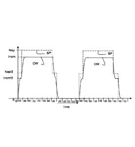
Fig. 3a depicts a diagram representing modulation of a light source in
accordance with the
invention. A driver system according to the invention and driving the light
source is
characterized in that it defines a set-point update rate with a corresponding
set-point update
period At, which is the smallest time period possible between different set-
point values. The
set-point update period At may for instance be 26ps, which has the advantage
that it is
compatible with 50Hz, 60Hz and high speed (3.3ms) video cameras.
When a code is to be emitted by the light source, the code is converted into a
sequence of
different current levels, which current levels are maintained for a
predetermined period of
time. In this example, the current levels making up the code are the !nom
value and the zero
(0) value which correspond to the nominal set-point value Nsp and the zero (0)
value,
respectively.
In accordance with the present invention, care is taken to realise a gradual
change between
a first current level and a second, different, current level, thereby making
use of one or more
intermediate set-point values in a range between, but not including, a first
set-point value
(associated with or corresponding to the first current value) and a second set-
point value
(associated with or corresponding to the second current value).
As shown in Figure 3a, the set-point SP generated makes use of an intermediate
level of
value 0.5Nsp for one set-point update period At when switching between the Nsp
value and
the zero value. As a result thereof the transitions between different current
levels making up
the code take more than one set-point update period At, so that the average
slope during
the transition is less steep than in the prior art method of modulating the
light source as for
instance shown in Fig. 2a or 2b. Comparing Figures 2b and 3a, it takes the
current CW in
Figure 3a approximately two times the set-point update period At to reach the
nominal value
!nom, whereas in Figure 2b, the nominal value is reached after approximately
one set-point
update period At.
7
CA 02953312 2016-12-21
WO 2015/199538 PCT/NL2015/050462
Figure 3b schematically shows an array of set-points 300 as may be applied in
an
embodiment of the present invention to realise the current transition as shown
in Figure 3a.
The set-points as schematically indicated by the arrows 310, 312 (arrows 312
representing a
set-point value equal to zero) are spaced apart over a period equal to the set-
point update
period At as shown in Figure 3a.
The dotted graph SP shows, as in Figure 3a, the envelope of the array of set-
points as
applied, whereas graph OW shows the corresponding current waveform OW through
the
light source alternating between a nominal current !nom corresponding to the
nominal set-
point value Nsp and a zero (0) value. In contrast to the array of set-points
as shown in
Figure 2a, the array of set-points 300 does not change from a value equal to
zero to a value
equal to Nsp instantaneously but, in the embodiment as shown, there is an
intermediate set-
point value Nsp/2 applied at instances t = 0 and t = t1, thereby realising a
more gradual
change in current I when the current is to change from I = 0 to I = !nom.
As the intensity of the emitted light changes more gradually, the chance of a
human
observer perceiving the intensity change as flicker is reduced. Further, other
optical read-out
devices such as a bar code scanners have more time to adapt itself to the
changing
intensity, thereby reducing the interference with these devices.
As the transitions between different current levels take more time, they also
have a larger
impact on the average intensity emitted by the light source. When only two
different current
levels are used, the impact of the transitions on the intensity is the same
each time, so that a
constant compensation factor can be used to adapt the predetermined time a
current level is
maintained in order to obtain a desired average intensity level. Hence, the
duty cycle may be
adjusted to compensate for deviations from a desired average intensity.
When more than two different current levels are used to form the code, the
impact of the
transitions on the intensity becomes dependent on the change between current
levels. In
such a case, compensation may be done over multiple pulses.
In an embodiment, it is possible to make an accumulative buffer to keep track
of the intensity
level during transitions and the deviations from the ideal square wave form,
so that the value
of the buffer can be used to compensate the predetermined periods a current
level is
maintained for the observed deviations, e.g. by adjusting the duty cycle.
Fig. 4 depicts schematically a luminaire LU according to an embodiment of the
invention.
The luminaire LU comprises a driver system DS and a light source LS. Input to
the driver
8
CA 02953312 2016-12-21
WO 2015/199538 PCT/NL2015/050462
system is energy I which may come from mains and is rectified by a power
source PS, but
the power source PS may also be a battery, so that no external input I is
required. An output
of the power source PS is fed to a light driver LD where for instance
filtering may take place
and where energy is outputted in a form, for instance a current, that is
suitable to drive the
light source.
The driver system DS of Fig. 4 further comprises a control unit CU and a
modulator M,
wherein the modulator M is configured to modulate the energy provided to the
light source.
The modulator may e.g. be configured to modulate a current as provided to the
light source,
thereby e.g. providing a sequence of different current levels that are
maintained during
different periods. In an embodiment, the modulator M may be configured to
provide in a
nominal current level and a zero current level. In such embodiment, the
modulator M thus
acts like an on/off switch. As schematically shown in Figure 4, the modulator
M and the light
driver LD are controlled by the control unit CU so that a predetermined
waveform of energy
is provided to the light source to illuminate the surroundings and for VCL.
The control unit is configured to carry out the method according to the
invention, so that the
control unit determines the different current levels and periods of time these
different current
levels need to be maintained in order to transmit a code using the light
source, wherein the
control unit ensures that the transition between different current levels
takes more than one
set-point update period thereby reducing the risk of flicker being perceived
by a human
observer and/or the risk of interference with other optical read-out devices.
As such, the
control unit may be configured, in an embodiment, to determine an array of set-
point values,
the array of set-point values providing in a gradual change between different
current levels
which form the code and provide the array of set-point values to the light
driver LD or the
light driver LD and the modulator M. In an embodiment, the control unit may be
configured to
receive a signal representative of the code to be transmitted by the light
source and convert
the code into a sequence of different current levels, which current levels are
maintained for
a predetermined period of time. In such embodiment, the control unit CU may
further be
configured to control the light driver or the light driver and the modulator
to provide the
sequence of different current levels to the light source LS such that the
light source emits
light at the different intensity levels. In accordance with the present
invention, the array of
set-point values are used at a set-point update rate having a set-point update
period, the
sequence of consecutive set-point values of the array of set-points being such
that
transitions between the different current levels take more than one set-point
update period.
As required, detailed embodiments of the present invention are disclosed
herein;
however, it is to be understood that the disclosed embodiments are merely
exemplary of the
invention, which can be embodied in various forms. Therefore, specific
structural and
9
CA 02953312 2016-12-21
WO 2015/199538 PCT/NL2015/050462
functional details disclosed herein are not to be interpreted as limiting, but
merely as a basis
for the claims and as a representative basis for teaching one skilled in the
art to variously
employ the present invention in virtually any appropriately detailed
structure. Further, the
terms and phrases used herein are not intended to be limiting, but rather, to
provide an
understandable description of the invention.
The terms "a" or "an", as used herein, are defined as one or more than one.
The term
plurality, as used herein, is defined as two or more than two. The term
another, as used
herein, is defined as at least a second or more. The terms including and/or
having, as used
herein, are defined as comprising (i.e., open language, not excluding other
elements or
steps). Any reference signs in the claims should not be construed as limiting
the scope of
the claims or the invention.
The mere fact that certain measures are recited in mutually different
dependent
claims does not indicate that a combination of these measures cannot be used
to
advantage.
The term coupled, as used herein, is defined as connected, although not
necessarily
directly, and not necessarily mechanically.
A single processor or other unit may fulfil the functions of several items
recited in the
claims.
10