Note: Descriptions are shown in the official language in which they were submitted.
SYSTEM AND METHODS FOR FABRICATING BORON NITRIDE
NANOSTRUCTURES
[0001]
STATEMENT OF GOVERNMENT SUPPORT
100021 This invention was made with government support under Contract No. DE-
ACO2-
05CH11231 awarded by the U.S. Department of Energy and Grant No. EEC-0832819
awarded
by the National Science Foundation. The government has certain rights in this
invention.
TECHNICAL FIELD
100031 This disclosure relates generally to boron nitride (BN) nanomaterials
and more
particularly to systems and methods for fabricating boron nitride
nanostructures.
BACKGROUND
100041 Boron nitride nanotubes (BNNTs), first synthesized in 1995 by Zettl and
collaborators, are wide-bandgap structural analogs to carbon nanotubes.
Importantly, the special
chemical, optical, thermal, and radiation-absorption properties of BNNTs make
them superior to
their carbon counterparts for many applications. Theoretical and experimental
studies
demonstrate that the electronic energy bandgap is ¨5eV, independent of tube
diameter and chirality,
but can be tuned by the application of transverse electric fields. A host of
other BNNT
properties have been considered, including tunable thermal conductivity,
piezoelectricity,
biocompatibility, hosts for silocrystal structures, electron field emission,
water purification, and
reinforcements for structural composites, to name just a few.
1
Date recue / Date received 2021-12-13
CA 02953492 2016-12-22
WO 2015/200496 PCMJS2015/037448
SUMMARY
[0005] A variable pressure (e.g., to 10 atmospheres), powder/gas/liquid
injection inductively
coupled plasma system has been developed and used to produce high quality
boron nitride
nanotubes (BNNTs) at continuous production rates of about 35 g/hour. Under
suitable
conditions, collapsed boron nitride nanotubes (i.e., nanoribbons), closed
shell boron nitirde
capsules (i.e., nanococoons), and nanosheets are also obtained. The process is
adaptable to a
large variety of feedstock materials.
[0006] One innovative aspect of the subject matter described in this
disclosure can be
implemented in a method including generating a directed flow of plasma. A
boron-containing
species is introduced to the directed flow of the plasma. Boron nitride
nanostructures are formed.
In one embodiment, the boron nitride nanostructures are formed in a chamber.
[0007] Another innovative aspect of the subject matter described in this
disclosure can be
implemented in a method including generating a directed flow of plasma using
nitrogen gas. A
boron-containing species is introduced to the directed flow of the plasma. The
boron-containing
species consists of boron powder. Boron nitride nanostructures are formed in a
chamber, with a
pressure in the chamber being about 3 atmospheres or greater.
[0008] Another innovative aspect of the subject matter described in this
disclosure can be
implemented in a system including a chamber and an inductively coupled plasma-
generating
torch attached to the chamber. The system is configured to: (a) generate a
directed flow of
plasma with the inductively coupled plasma-generating torch using nitrogen
gas, a pressure in
the chamber being about 3 atmospheres or greater; (b) introduce a boron-
containing species to
the directed flow of the plasma; and (c) form boron nitride nanostructures in
the chamber.
[0009] Details of one or more embodiments of the subject matter described
in this
specification are set forth in the accompanying drawings and the description
below. Other
features, aspects, and advantages will become apparent from the description,
the drawings, and
the claims. Note that the relative dimensions of the following figures may not
be drawn to scale.
BRIEF DESCRIPTION OF THE DRAWINGS
[0010] Figure 1 shows an example of a cross-sectional schematic
illustration of an Extended
Pressure Inductively Coupled (EPIC) synthesis system.
2
CA 02953492 2016-12-22
WO 2015/200496 PCMJS2015/037448
[0011] Figure 2 shows an example of a flow diagram illustrating a method
for fabricating
boron nitride nanostructures.
[0012] Figures 3A-3C show examples of SEM images of as-synthesized BNNTs
obtained
from fibril-like material near the center of the chamber.
[0013] Figure 4A and 4B show example of high resolution TEM images of BNNTs
produced
by EPIC synthesis.
[0014] Figure 5 shows an example of electron energy loss spectroscopy
(EELS) for a BNNT
produced by EPIC synthesis.
[0015] Figure 6 shows an example of a Raman spectrum of a BNNT produced by
EPIC
synthesis.
[0016] Figure 7A shows an example of a TEM image of boron nitride
nanococoons, filled
with boron.
[0017] Figure 7B shows an example of a TEM image of a twisted boron nitride
nanoribbon
derived from a flattened BNNT.
DETAILED DESCRIPTION
[0018] Reference will now be made in detail to some specific examples of
the invention.
Examples of these specific embodiments are illustrated in the accompanying
drawings. While the
invention is described in conjunction with these specific embodiments, it will
be understood that
it is not intended to limit the invention to the described embodiments. On the
contrary, it is
intended to cover alternatives, modifications, and equivalents as may be
included within the
spirit and scope of the invention as defined by the appended claims.
[0019] In the following description, numerous specific details are set
forth in order to
provide a thorough understanding of the present invention. Particular example
embodiments of
the present invention may be implemented without some or all of these specific
details. In other
instances, well known process operations have not been described in detail in
order not to
unnecessarily obscure the present invention.
[0020] Various techniques and mechanisms of the present invention will
sometimes be
described in singular form for clarity. However, it should be noted that some
embodiments
include multiple iterations of a technique or multiple instantiations of a
mechanism unless noted
otherwise.
3
CA 02953492 2016-12-22
WO 2015/200496 PCMJS2015/037448
INTRODUCTION
[0021] An unfortunate constraint that has severely limited the scientific
study and industrial
application of BNNTs and related BN-based nanostructures (e.g., such as BN
nanoribbons
(BNNRs), BN nanococoons (BNNCs). and BN nanosheets) is the general lack of
availability of
the synthesized materials. The original arc-plasma synthesis method of BNNTs
has seen some
refinements, but generally it is not readily scalable. Other synthesis methods
have been
advanced, including laser vaporization, chemical vapor deposition, plasma
torch, ball milling and
annealing, and templated conversion. Another technique in BNNT synthesis is
the use of a laser
ablation technique to create small-wall-number, highly crystalline, and high
aspect ratio pure
BNNTs. Unfortunately, this laser-vaporization method suffers from low energy
efficiency as
well as limited throughput (approximately 100 mg/hour).
SYSTEM AND METHODS
[0022] The operation of a high-throughput, scalable BN nanostructure
synthesis process
whereby precursor materials are directly and continuously injected into a high-
temperature,
Extended Pressure Inductively Coupled (EPIC) plasma synthesis system is
described herein. The
EPIC synthesis system is versatile in terms of synthesis parameters and allows
for the injection
of fluids (e.g., gases or liquids) and solids (e.g., powders) directly into a
variable-power plasma
plume. In addition, the high-pressure capability of the plasma (e.g., up to 10
atm) allows for
shifts in chemical reactions. The system can be operated in a near-continuous
fashion and thus
far has achieved a record output of over 35 g/hour for pure, small diameter,
few wall, highly
crystalline BNNTs.
[0023] Inductively coupled thermal plasma systems typically operate at
reduced pressure
(e.g., I atmosphere and below). Further, inductively coupled thermal plasma
systems typically
operate using argon (A r) gas to generate a plasma, as it has been thought
difficult to maintain a
plasma in such a system with nitrogen (N2) gas. Nitrogen is a diatomic gas,
while a more
conventional plasma gas, such as argon, is monoatomic. Plasmas are generally
more difficult to
maintain with diatomic gasses in part because of the dissociation energy of
the diatomic gas. No
commercial system existed that was capable of operating within the parameter
ranges described
4
CA 02953492 2016-12-22
WO 2015/200496 PCMJS2015/037448
herein (e.g., including high pressure, pure nitrogen operation). Therefore, a
suitable EPIC
synthesis system was designed and built.
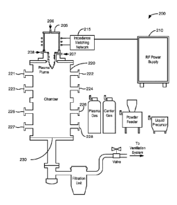
[0024] Figure 1 shows an example of a cross-sectional schematic
illustration of an Extended
Pressure Inductively Coupled (EPIC) synthesis system 200 for scaled synthesis
of BNNTs and
related materials. An inductively coupled plasma-generating torch 205, driven
by a power supply
210 and a matching network 215, is attached to a chamber 220. In some
embodiments, the
inductively coupled plasma-generating torch 205 is powered with a power supply
210 that is an
AC power supply. In contrast, a DC arc plasma torch is powered with a DC power
supply. In
some embodiments, an inductively coupled plasma is advantageous in the
fabrication of boron
nitride nanomaterials, because of the larger plasma volume, the low plasma gas
velocity, and the
longer reaction time associated with an inductively coupled plasma. Due to the
absence of
electrodes in an inductively coupled plasma-generating torch, an inductively
coupled plasma-
generating torch may be relatively maintenance free and does not introduce
contamination from
electrodes in the materials being fabricated; a DC arc plasma torch does have
electrodes. Further,
an inductively coupled plasma-generating torch may offer greater flexibility
in the control of the
operating parameters compared to a DC arc plasma torch.
[0025] For example, for a laboratory-scale embodiment of the system 200,
the power supply
210 may be a 60 kW, 7 MHz power supply and the chamber 220 may have a 15
centimeters (cm)
inner diameter and be 112 cm long. All of the experiments described in the
EXAMPLES section
were performed with such a laboratory-scale embodiment. A larger system,
including a larger
chamber and a more powerful power supply, may be used in an industrial
implementation of an
EPIC synthesis system.
[0026] In some embodiments, the plasma-generating torch 205 includes a
plasma chamber of
a dielectric material (e.g., a high-temperature dielectric material). In some
embodiments, the
dielectric material of the plasma chamber comprises quartz or alumina (i.e.,
aluminum oxide). In
some embodiments, the plasma chamber is a composite structure, with an inner
water-cooled
porous structure surrounded by an alumina cylinder. In some embodiments, coils
configured to
be driven by a radio frequency signal are wrapped around the plasma chamber.
[0027] In some embodiments, the plasma-generating torch 205 includes
several ports for the
introduction of materials. Ports 206, 207, and 208 in the plasma-generating
torch 205 may be
used for injection of plasma gas and/or feedstock near the plasma plume. For
example, the
CA 02953492 2016-12-22
WO 2015/200496 PCMJS2015/037448
plasma gas (e.g., nitrogen or a mixture of nitrogen and argon) can be
introduced at the port 206,
and boron feedstock (e.g., boron powder, boron nitride, boron carbide, boron
trioxide, boric acid,
or a mixture of carbonaceous material and an oxide of boron) can be injected
into the plasma
plume via the port 207. Other modes of operation are possible, such as co-
injection of the plasma
gas and boron feedstock through the port 206, or introducing the plasma gas
through the port 208
where the gas first swirls upward along the inner wall of the torch body and
then back down the
center. Powder feedstock can be input using a commercial powder feeder using a
carrier gas,
while liquids/gases can be directly injected.
[0028] Several access ports in the chamber 220 may provide access to the
interior of the
chamber 220. For example, access ports 221-228 may be used for diagnostics
(e.g., such as
optical monitoring of the reaction), for the insertion of quench modifiers
(e.g., such as wires or
meshes), or for pressure-assisted purging of synthesized material. In some
embodiments, the
chamber 220 may include fewer access ports, more access ports, or no access
ports.
[0029] In some embodiments, due to the flow of nitrogen or other gasses
used to generate a
plasma with the plasma-generating torch 205, the chamber 220 includes a port
230 though which
gasses may be vented. Fixtures (e.g., a valve, a needle valve, or a gas
metering device) associated
with the port 230 may be adjusted to maintain a desired pressure in the
chamber 220.
[0030] In some embodiments, the system 200 (e.g., the power supply 210, the
plasma-
generating torch 205, and the chamber 220) may be actively cooled when in
operation to allow
for continuous operation and to aid in ensuring suitable thermal quench
gradients within the
chamber 220. In some embodiments, the system 200 may be water-cooled.
[0031] In some embodiments, synthesized material can be collected manually
from the
opened chamber 220. In some embodiments, synthesized material can be collected
via an in-situ
pressure-purge extraction cycle, which may afford near-continuous (i.e.,
rather than batch)
operation. For example, additional vessels may be attached to ports 221-228
with valves
between these vessels and the chamber 220. By pressuring and/or evacuating
these vessels, the
synthesized material can be driven from the main chamber 220 by opening the
valves and
forcing the synthesized material into various vessels for collection. In some
embodiments, the
synthesized materials can be collected on, for example, a wire or wire mesh
that is introduced
into the chamber through one of the ports (221-228) and out of the chamber
through another port
(221-228) to a vessel where it can be collected.
6
CA 02953492 2016-12-22
WO 2015/200496 PCMJS2015/037448
[0032] The power density and volume of the plasma plume, which have bearing
on the
temperature, residence time of precursor materials, and quench rates in the
reaction zone, can be
modified at a given pressure by varying the input power and gas flow rates.
Quench rates may be
further adjusted by varying the cooling of the chamber 220 by adjusting the
cooling water
flow rate) or by lining the interior wall of the chamber 220 with thermal
blankets (e.g., in some
runs described in the EXAMPLES section, carbon felt of about 1.3 cm thickness
was used). For
a typical run described in the EXAMPLES section, the plasma gas was pure N2
injected into port
206, and the boron feedstock was pure boron powder or hexagonal boron nitride
(hBN) powder
injected via a powder feeder and pure N., carrier gas into port 207.
[0033] In some embodiments, an EPIC synthesis system also includes a system
controller
having instructions for controlling process operations in accordance with the
disclosed
embodiments. The system controller may include one or more memory devices and
one or more
processors configured to execute the instructions so that the system will
perform methods in
accordance with the disclosed embodiments. Machine-readable media containing
instructions for
controlling process operations in accordance with the disclosed embodiments
may be coupled to
the system controller.
[0034] All of the methods described herein can be performed using the
system 200 or similar
embodiments of the system 200.
[0035] Figure 2 shows an example of a flow diagram illustrating a method
for fabricating
boron nitride nanostructures. Starting at block 110 of the method 100 shown in
Figure 2, a
directed flow of plasma is generated.
[0036] In some embodiments, the directed flow of the plasma is generated
using a plasma-
generating torch. A plasma-generating torch may also be referred to as a
plasma arc or a plasma
gun. In some embodiments, the plasma-generating torch is an inductively
coupled plasma-
generating torch. In some embodiments, the plasma-generating torch is powered
with a radio
frequency (RF) power supply (e.g., a RF power supply with a power of about 60
kilowatts (kW)
and a frequency of about 7 Hz). For example, to generate a directed flow of
plasma with the
laboratory-scale embodiment of the EPIC synthesis system, the nitrogen flow
rate may be about
25 liters per minute (liters/min) to about 75 liters/min, about 40 liters/min
to about 60 liters/min,
or about 50 liters/min, and the RF power may be about 40 kW to about 50 kW.
7
CA 02953492 2016-12-22
WO 2015/200496 PCMJS2015/037448
[0037] In some embodiments, nitrogen, argon, hydrogen, or mixtures thereof
are used to
generate the directed flow of the plasma. In some embodiments, nitrogen (i.e.,
nitrogen gas) is
used to generate the directed flow of the plasma. In some embodiments,
nitrogen gas only is used
to generate the directed flow of the plasma. In some embodiments,
substantially nitrogen gas
(i.e.., nitrogen gas that may include impurities, such as water) only is used
to generate the
directed flow of the plasma. In some embodiments, at least 50% of the gas used
to generate the
plasma is nitrogen gas. In some embodiments, at least 90% of the gas used to
generate the
plasma is nitrogen gas. In some embodiments, at least 95% of the gas used to
generate the
plasma is nitrogen gas.
[0038] At block 120, a boron-containing species is introduced to the
directed flow of the
plasma. In some embodiments, the boron-containing species includes hexagonal
boron nitride
powder. In other embodiments, the boron-containing species does not include
hexagonal boron
nitride powder. In some embodiments, the boron-containing species includes
boron powder. In
some embodiments, the boron-containing species includes only boron powder. In
some
embodiments, the boron-containing species includes amorphous boron powder or
only
amorphous boron powder. In some embodiments, the boron-containing species
includes
crystalline boron powder or only crystalline boron powder.
[0039] Other precursors also can be used to fabricate boron nitride
nanostructures. For
example, in some embodiments, the boron-containing species comprises an oxide
of boron or an
acid of boron. In some embodiments, the oxide of boron is selected from a
group consisting of
boron trioxide (B203) and diboron dioxide (B202). In some embodiments, the
acid of boron
comprises boric acid (H3B03). In some embodiments, the boron-containing
species as a gas,
such as diborane gas or boron trichloride gas.
[0040] In some embodiments, the boron-containing species comprises a powder
and is
introduced to the directed flow of the plasma using a carrier gas. In some
embodiments, nitrogen
is used as the carrier gas. Both the nitrogen in the directed flow of the
plasma and the nitrogen in
the carrier gas may react with boron from the boron-containing species to form
boron nitride
nanostructures.
[0041] In some embodiments, blocks 110 and 120 may be considered to occur
simultaneously. For example, when the boron-containing species and the gas
used to generate the
directed flow of the plasma (i.e., the plasma gas) are fed into the plasma-
generating torch 205
8
CA 02953492 2016-12-22
WO 2015/200496 PCMJS2015/037448
simultaneously through the same port, the directed flow of the plasma may be
generated as the
boron-containing species are introduced to the directed flow of the plasma.
[0042] At block 130, boron nitride nanostructures are formed. In some
embodiments, the
boron nitride nanostructures form due to cooling of the directed flow of the
plasma. In some
embodiments, the boron nitride nanostructures form in a chamber, such as
chamber 220
described above. In some embodiments, boron nitride nanostructures form on the
interior walls
of the chamber. In some embodiments, boron nitride nanostructures form
throughout the
chamber. In some embodiments, the materials are collected on a removable
jacket inside the
chamber. In some embodiments, the materials are collected using the methods
described above
(e.g., opening the chamber or an in-situ pressure-purge extraction cycle). In
some embodiments,
the boron nitride nanostructures comprise or are selected from a group
consisting of nanotubes,
nanoribbons, nanococoons (e.g., closed shell capsules of boron nitride), and
nanosheets. A boron
nitride nanoribbon may be defined as one-dimensional sheet of boron nitride
having nanometer
scale dimensions in thickness and width and a length on the order of microns.
A boron nitride
nanosheet may be defined as a hexagonal boron nitride crystal having
dimensions along the c-
axis of the crystal of about 50 nm to 150 nm, about 100 nm, or less than about
1 micron, and
having dimensions along the a-axis and the b-axis of the crystal on the order
of microns.
[0043] In some embodiments, a pressure (e.g., a nitrogen pressure) in the
chamber is about
0.5 to about 1.5 atmosphere (atm), for example about 1 atm. A nitrogen
pressure of about 0.5 to
about 1.5 atm may aid in the formation of boron nitride nanococoons (i.e., a
shell of boron
nitride surrounding a boron particle or a boron nitride nanostructure
surrounding a boron
particle). In some embodiments, a pressure (e.g., a nitrogen pressure) in the
chamber is about 1.5
to about 2.5 atm, for example about 2 atm. A nitrogen pressure of about 1.5 to
about 2.5 atm may
aid in the formation of boron nitride nanoribbons (i.e., a collapsed boron
nitride nanotube,
flattened into a ribbon or sheet of boron nitride). As the plasma-generating
torch used to generate
the directed flow of the plasma may enclose a portion of the chamber, the
pressure (e.g., the
nitrogen pressure) may be at these pressure levels during blocks 110, 120. and
130 of the method
100.
[0044] In some embodiments, a pressure (e.g., a nitrogen pressure) in the
chamber is about 3
atm or greater. In some embodiments, a pressure (e.g., a nitrogen pressure) in
the chamber is
between 3 atm and 100 atm. In some embodiments, a pressure (e.g., a nitrogen
pressure) in the
9
CA 02953492 2016-12-22
WO 2015/200496 PCMJS2015/037448
chamber is between 3 atm and 10 atm. A nitrogen pressure of about 3 atm or
greater may aid in
the formation of boron nitride nanotubes. In some embodiments, a pressure
(e.g., a nitrogen
pressure) in the chamber is between 1 atm and 100 atm. In some embodiments, a
pressure (e.g., a
nitrogen pressure) in the chamber is between 2 atm and 10 atm. As the plasma-
generating torch
used to generate the directed flow of the plasma may enclose a portion of the
chamber, the
pressure (i.e., the nitrogen pressure) may be at these pressure levels during
blocks 110, 120, and
130 of the method 100.
[0045] In some embodiments, a percentage of the boron nitride
nanostructures that are
nanotubes is about 90% or greater. For example, when the pressure in the
chamber is about 3 atm
or higher, nanotubes may comprise about 90% or more of the boron nitride
nanostructures.
Pressures above about 3 atm may generate larger percentages of boron nitride
nanotubes. In
some embodiments, a percentage of the boron nitride nanostructures that are
nanotubes is about
50% or greater.
[0046] In some embodiments, a catalyst may be used to fabricate the boron
nitride
nanostructures. For example, a catalyst may be introduced to the directed flow
of the plasma at
block 120. Generally, a catalyst is a substance that may be used to increase
the rate of a chemical
reaction without being consumed by the reaction. Some metal catalysts that
have been used to
fabricate boron nitride nanostructures include magnesium and tungsten; these
catalysts are
generally present in small amounts. For example, a catalyst may be present in
an amount of less
than about 1%, by atomic ratio, of boron and nitrogen. In some embodiments,
hydrogen may be
used to aid in the formation of boron nitride nanostructures; hydrogen may be
considered a
catalyst in these instances. For example, hydrogen, in part, may be used to
generate the plasma,
and may also serve to aid in the formation of boron nitride nanostructures. In
some
embodiments, hydrogen may be introduced to the directed flow of the plasma.
[0047] In some embodiments, boron nitride nanostructures are formed without
the use of a
catalyst. In some embodiments, boron nitride nanostructures are formed without
the use of a
metal catalyst. In some embodiments, boron nanostructures are formed without
the use of
hydrogen. For example, pressures of 1 atm or greater when forming boron
nitride nanostructures
may obviate any need to use a catalyst or hydrogen in a boron nitride
nanostructure fabrication
process.
CA 02953492 2016-12-22
WO 2015/200496 PCMJS2015/037448
[0048] In some embodiments, the chamber is actively cooled during blocks
110, 120, and
130. For example, the chamber may be actively cooled using water. In some
embodiments, the
amount that the chamber is cooled can be adjusted to adjust the cooling rate
of the directed flow
of the plasma. In some embodiments, the cooling rate of the directed flow of
the plasma
determines, in part, the type of boron nitride nanostructures that are formed.
[0049] In some embodiments, a structure may be placed in the chamber such
that the
directed flow of the plasma impinges the structure. This may cool the plasma
rapidly and allow
for the synthesis of desired boron nitride nanostructures. Also, boron nitride
nanostructures may
form on the structure. For example, the structure may include surfaces, wires.
meshes, or screens
positioned in the chamber so that the directed flow of the plasma impinges the
structure. In some
embodiments, the structure may be actively cooled while performing the method
100. For
example, the structure may be actively cooled with water.
[0050] In some embodiments, the method further comprises introducing a
carbon-containing
species to the directed flow of the plasma. In some embodiments, the carbon-
containing species
is selected from a group consisting of amorphous carbon, carbon black.
graphite, carbon
nanotubes. graphene, and graphite oxide. In some embodiments. the carbon-
containing species
are used when the boron-containing species comprises an oxide of boron or an
acid of boron.
[0051] In some embodiments using a carbon-containing species, the directed
flow of the
plasma is generated with nitrogen, argon, hydrogen, and mixtures thereof. In
some
embodiments, the directed flow of the plasma is generated with nitrogen (i.e.,
nitrogen gas). In
some embodiments, the directed flow of the plasma is generated with nitrogen
gas only. In some
embodiments, the directed flow of the plasma is generated with substantially
nitrogen gas (i.e.,
nitrogen gas that may include impurities) only.
[0052] In some embodiments, the boron-containing species and the carbon-
containing
species are introduced to the directed flow of the plasma as a mixture. For
example, the mixture
of the boron-containing species and the carbon-containing species could be
introduced to the
directed flow of the plasma through one of the ports 206, 207, or 208 of the
plasma-generating
torch 205 of the system 200. In some embodiments, the boron-containing species
and the carbon-
containing species are physically separated from one another when introduced
to the directed
flow of the plasma. That is, the boron-containing species and the carbon-
containing species are
not a mixture when each species is introduced to the directed flow of the
plasma. For example,
11
CA 02953492 2016-12-22
WO 2015/200496 PCMJS2015/037448
one of the species could be introduced to the directed flow of the plasma
through the port 206,
and the other of the species could be introduced to the directed flow of the
plasma through the
port 207 of the plasma-generating torch 205 of the system 200.
[0053] In some embodiments, when the boron-containing species comprising an
oxide of
boron or an acid of boron and the carbon-containing species are introduced to
the directed flow
of the plasma, a catalyst is also introduced to the directed flow of the
plasma. In such
embodiments, a catalyst is used to fabricate the boron nitride nanostructures.
In some
embodiments, the catalyst comprises magnesium (Mg), iron (Fe), nickel (Ni),
cobalt (Co),
yttrium (Y), lithium (Li), copper (Cu), lithium oxide (Li0), and/or calcium
oxide (CaO). In some
embodiments, the catalyst is mixed with the boron-containing species, the
carbon-containing
species, or both. In some embodiments, the catalyst is not mixed with the
boron-containing
species or the carbon-containing species when it is introduced to the directed
flow of the plasma.
In some embodiments, when the boron-containing species comprising an oxide of
boron or an
acid of boron and the carbon-containing species are introduced to the directed
flow of the
plasma, a catalyst is not introduced to the directed flow of the plasma. In
such embodiments, a
catalyst is not used to fabricate the boron nitride nanostructures.
[0054] While not wanting to be bound by any theory, the reaction when the
boron-containing
species comprising an oxide of boron or an acid of boron and the carbon-
containing species are
introduced to the directed flow of the plasma is:
3C + B203+ N2 ¨> 2BN +3C0.
[0055] Other compositions of nanostructures may also be fabricated using
the EPIC
synthesis system 200 and other embodiments of the method 100. For example,
boron carbon
nitrogen (B,CyN,) nanostructures (including nanotubes, nanoribbons,
nanococoons, and
nanosheets) may be fabricated using a method similar to the method 100 by
adding a carbon-
containing species to the directed flow of the plasma. In some embodiments,
transition metals
(e.g., iron, nickel, and copper) may be used as a catalyst in the formation of
RCN nanostructures.
In some embodiments, BCN nanostructures may be formed without the use of a
catalyst.
EXAMPLES
[0056] The following examples are intended to be examples of the
embodiments disclosed
herein, and are not intended to be limiting.
12
CA 02953492 2016-12-22
WO 2015/200496 PCMJS2015/037448
[0057] Methods of fabricating BNNTs with a laboratory-scale EPIC synthesis
system can
generate high quality materials at production rates of about 35 g/hour. In the
examples below, no
quench wires or screens were used, the plasma gas was pure nitrogen injected
via the port 206 of
the system 200 shown in Figure 1, and the boron feedstock was either hexagonal
BN (hBN)
powder (e.g., -325 mesh) or amorphous boron powder (e.g., -325 mesh) delivered
by a nitrogen
carrier gas. The process was performed without use of a catalyst. Both types
of boron feedstock
successfully produced BNNTs (and with suitable parameter adjustment, other BN
nanomaterials). A higher conversion rate was achieved with amorphous boron
powder.
Nitrogen as the carrier gas (e.g., at about 2 liters/min to 5liters/min) was
used to propel the
powder radially into the plasma plume via port 207 of the system 200 near the
torch nozzle at
pressures varying from about 14.7 psia to 75 psia (psi absolute), with boron
injection rates of
about 100 mg/min to 1700 mg/min. Nitrogen flowing at about 50 liters/min
served as the plasma
gas with the plasma power maintained at about 40 kW to 50 kW. Experiments were
typically of
duration of about ten minutes to one hour.
[0058] With amorphous boron at 246 mg/min, carrier gas N, at 2.5 1/m,
plasma gas N, at 50
1/m, and 40 kW plasma at 30 psia, the EPIC synthesis system immediately
generated fibrous,
light-colored, cotton-candy web-like material which soon occupied the entire
cross-sectional area
of the chamber. The material initially accumulated in the upper half of the
chamber (i.e., near the
torch hot zone), and, as the run continued, the chamber got successively
packed, filling a volume
of 10 liters (i.e., half the total chamber volume) in approximately 30
minutes. In conjunction
with fibrils packing the interior volume of the chamber, the chamber walls
typically also became
coated in a similarly light colored material, which was easily peeled off as a
continuous felt-like
film. Often the fibril and felt materials had an overall light grayish color,
which on closer
inspection revealed itself as pure-white cottony patches dispersed among
grayish material.
Compressed BNNT fibril material (e.g., from a 15 minute synthesis run) filled
a one-liter glass
jar. The material was composed largely of double-wall BNNTs.
[0059] The fibril cotton-candy-like and felt-like sheet material was
characterized. Over a
broad range of synthesis conditions, both were composed predominantly of pure
BNNTs with
wall number ranging from two to six, with the most common being double¨wall
tubes of outer
diameter ¨4 nm similar to those observed using other BNNT synthesis
techniques. The grayish
13
CA 02953492 2016-12-22
WO 2015/200496 PCMJS2015/037448
color originated from dark specks of unreacted boron not incorporated into the
pure-white (or
rather transparent) tubes, and could be removed by treatment in a nitric acid
solution.
[0060] For the boron nitride material characterized in Figures 3-6, the
following parameters
were used to generate the material: amorphous boron at150 mg/min; carrier gas
N2 at 2.5 1/m;
plasma gas N2 at 50 Um; 40 kW plasma at 45 psia.
[0061] The nanoscopic morphology and purity of the BNNT-containing material
were
observed using scanning electron microscopy (SEM) with energy dispersive x-ray
analysis
(EDAX) capability and transmission electron microscopy (TEM, operating at 80
kV). Element-
sensitive electron energy loss spectroscopy (EELS) was performed using a TEM
operated at
200kV. Raman spectra were collected on a spectrometer using a 514 nm
excitation laser.
[0062] Figures 3A-3C show characteristic SEM images of the fibril-like
material removed
from the center of the chamber. The low-density spongy material consisted of
millimeter to
centimeter (or longer) whispy fiber bundles, with rough macroscopic alignment
of the fibrils
(Figure 3A). At higher magnification (Figures 3B and 3C) the fibrils are seen
to be composed of
individual nanotubes (identified as pure BNNTs). This and related imaging
shows that the tubes
have lengths exceeding tens of microns. At the zoomed in scale (Figure 3C) the
origin of the
grayish patches of the bulk material was revealed as unreacted nanoscale
particles of solid boron
(identified by EDAX) interspersed among the pure tubes and fibrils.
[0063] High resolution TEM images of individual BNNTs within the fibrils
are presented in
Figures 4A and 4B. Figure 4A shows a typical BNNT bundle (e.g., in this
micrograph, double-
wall BNNTs), while Figure 4B shows details of individual tubes. In Figure 4B,
tubes with wall
number, n, ranging from two to six are shown, with outer diameters, indicated
by d, spanning 4
nm to 6 nm. The TEM analysis verified the hollow, tubular nature of the BNNTs.
Counting tubes
in multiple TEM sessions showed that the majority of the BNNTs were double
walled (70%)
with the next most predominant being triple walled (20%); this 90%
distribution has diameters
ranging from 2 rim to 6 nm. The majority of the remaining 10% of the BNNTs
were multiwall
nanotubes with wall number n>3, with only a very sparing amount of n=1
nanotubes. The multi-
wall BNNTs were generally highly crystalline with straight walls with no
"bamboo" or "Dixie-
cup" like defects. The high crystallinity of the as-synthesized BNNTs was
reconfirmed in
selected area electron diffraction. The structural quality of the tubes was
significantly higher than
14
CA 02953492 2016-12-22
WO 2015/200496 PCMJS2015/037448
that seen for most other BNNT synthesis techniques and is comparable to that
for BNNTs
produced by the laser vaporization method.
[0064] Figure 5 shows an EELS spectrum from a BNNT collected from the
fibril region.
Prominent boron and nitrogen peaks with sp2-hybridization signatures were
clearly observed,
yielding an atomic B/N ratio of 1.0/0.8, in agreement (considering
experimental uncertainties)
with the expected 1/1 atomic ratio for pure BNNTs. Figure 6 shows a Raman
spectrum for a
BNNT, again collected from the fibril, chamber-center region. The peak at 1367
cm-I is
attributable to the E2g vibration mode of sp2-bonded BNNTs. The sharpness of
the peak (FWHM
is 11 cm-I) indicates highly crystalline "graphitic" BN.
[0065] The EPIC synthesis system displays great versatility for tuning
synthesis conditions.
Variable pressure, carrier gas, feedstock type, and injection rate of the
feedstock all provide for a
unique environment to grow not only high quality high aspect ratio BNNTs, but
also other BN-
based nanostructures. The experimental conditions under which various BN
nanomaterials are
synthesized can also elucidate the ways in which the nanostructures are
formed. By tuning the
reaction parameters, various forms of BN nanostructures can be targeted.
[0066] For BNNTs synthesis from pure boron and nitrogen, the overall
reaction is
2B +N2 2BN
This reaction rate is expected to increase under high pressure of nitrogen,
and indeed that is what
was observed with the EPIC synthesis system. At 1 atm pressure, while some
BNNTs were
formed, there was also a considerable amount of boron that has not completely
reacted with
nitrogen to form BN. In this case there can be a shell, or nanococoon, of BN
around the boron
particles. Figure 7A shows examples of boron-filled BN nanococoons so produced
with no post-
processing. For the material in Figure 7A, the following synthesis conditions
were used:
amorphous boron at 150 mg/min, carrier gas N2 at 2.5 1/m, plasma gas N2 at 50
1/m, and 40 kW
plasma at 25 psia.
[0067] At pressures above 2 atm, the concentration of these nanococoons
began to decrease
and, at 3 atm and above, they composed a very small fraction of the resulting
product. While this
indicates that high pressure nitrogen environments can assist high purity BNNT
synthesis, it also
hints at the mechanism of BNNT formation: as boron is injected into the plasma
plume, it
becomes a molten droplet. The surface of this droplet reacts with the nitrogen
while within and
as it exits the plasma plume. Higher pressure of nitrogen increases the energy
density of the
CA 02953492 2016-12-22
WO 2015/200496 PCMJS2015/037448
plasma plume and the collision rate of nitrogen atoms with the boron droplet,
and thereby shifts
the reaction toward BN in Equation 1. When the nitrogen pressure is relatively
low, the boron
does not react completely, thus enabling BN nanococoons. As the nitrogen
pressure increases,
the boron droplet completely reacts forming mostly BNNTs. Hence, the EPIC
synthesis system
allows tailoring of BN-based nanoparticle growth, and thereby various forms of
non-nanotube
BN nanostructures can be produced in significant quantities (though in
preliminary studies, not
yet exclusively).
[0068] Along similar lines, under appropriate synthesis conditions the EPIC
synthesis system
can also form a large fraction of collapsed BNNTs. For carbon nanotubes, it
has been shown that
for some types of nanotubes (e.g., few enough wall number and large enough
diameter), the
more stable configuration for a nanotube is not the conventional "inflated"
tube of circular cross-
section, but rather a "collapsed" or flattened tube where the tube now
resembles more a ribbon.
Collapsed carbon nanotube ribbons have been experimentally observed. Previous
efforts have
examined deformed BN nanostructures by high temperature metal-catalyzed
reactions of
BNNTs, and alkali-driven "unzipping" of BNNTs has yielded BN-based ribbons,
but edge-free
flattened-BN ribbons derived from unadulterated collapsed BNNTs have not been
previously
reported. These structures are of interest as the flattening is predicted to
dramatically alter the
electronic structure of the tube, allowing band gap engineering, and
mechanically-modulated
optoelectronic devices.
[0069] Figure 7B shows a high-resolution TEM image of a collapsed BNNT,
flattened into a
twisted ribbon, produced by EPIC synthesis with no post-processing. For the
material in Figure
7B, the following synthesis conditions were used: amorphous boron at 150
mg/min, carrier gas
N2 at 2.5 1/m, plasma gas N2 at 50 Um, 40 kW plasma ramped from 15 to 45 psia.
CONCLUSION
[0070] In summary, a versatile, scalable, high-throughput synthesis method
for the
production of highly-crystalline, low-wall-number, high aspect ratio BNNTs has
been
demonstrated. The direct-injection EPIC synthesis system allows for a wide
range of synthesis
parameters, including catalyst-free BNNT production at a rate thus far of
about 35 g/hour, nearly
300 times the production rate of the laser vaporization method. Additional BN-
based
nanostructures such as nanococoons and collapsed-tube nanoribbons are
accessible. The EPIC
16
synthesis method should find further application in other synthesis
challenges, for example alloy
BõCyNz nanotubes, and importantly other nanostructures containing elements in
addition to or
other than boron and nitrogen.
100711 In the foregoing specification, the invention has been described with
reference to
specific embodiments. However, one of ordinary skill in the art appreciates
that various
modifications and changes can be made without departing from the scope of the
invention as set
forth in the claims below. Accordingly, the specification and figures are to
be regarded in an
illustrative rather than a restrictive sense, and all such modifications are
intended to be included
within the scope of invention.
REFERENCES
1. Chopra, N. G.; Luyken, R. J.; Cheney, K.; Crespi, V. H.; Cohen, M. L.;
Louie, S. G.;
Zettl, A. Science 1995, 269, (5226), 966-967.
2. Rubio, A.; Corkin, J. L.; Cohen, M. L. Phys Rev B 1994, 49, (7), 5081-
5084.
3. Iijima, S. Nature 1991, 354, (6348), 56-58.
4. Cohen, M. L.; Zettl, A. Phys Today 2010, 63, (11), 34-38.
5. Blase, X.; Rubio, A.; Louie, S. G.; Cohen, M. L. Europhys Lett 1994, 28,
(5), 335-340.
6. Ishigami, M.; S au, J. D.; Aloni, S.; Cohen, M. L.; Zettl, A. Phys Rev
Lett 2005, 94, (5).
7. Jaffrennou, P.; Barjon, J.; Lauret, J. S.; Maguer, A.; Golberg, D.;
Attal-Tretout, B.;
Ducastelle, F.; Loiseau, A. physica status solidi (b) 2007, 244, (11), 4147-
4151.
8. Chang, C. W.; Han, W. Q.; Zettl, A. App! Phys Lett 2005, 86, (17).
9. Mele, E. J.; Kral, P. Phys Rev Lett 2002, 88, (5), 056803.
10. Chen, X.; Wu, P.; Rousseas, M.; Okawa, D.; Gartner, Z.; Zettl, A.;
Bertozzi, C. R. J Am
Chem Soc 2009, 131, (3), 890-+.
11. Mickelson, W.; Aloni, S.; Han, W. Q.; Cumings, J.; Zettl, A. Science
2003, 300, (5618),
467-469.
12. Cumings, J.; Zettl, A. Solid State Commun 2004, 129, (10), 661-664.
13. Hilder, T. A.; Gordon, D.; Chung, S. H. Small 2009,5, (19), 2183-2190.
14. Zhi, C.; Bando, Y.; Tang, C.; Honda, S.; Kuwahara, H.; Golberg, D.
Journal ofMaterials
Research 2006, 21, (11), 2794-2800.
17
Date recue / Date received 2021-12-13
CA 02953492 2016-12-22
WO 2015/200496 PCMJS2015/037448
15. Lahiri, D.; Hadjikhani, A.; Zhang, C.; Xing, T.; Li, L. H.; Chen, Y.;
Agarwal, A.
Materials Science and Engineering: A 2013, 574, (0), 149-156.
16. Cumings, J.; Zettl, A. Chem Phys Lett 2000, 316, (3-4), 211-216.
17. Golberg, D.; Bando, Y.; Eremets, M.; Takemura, K.; Kurashima, K.; Yusa,
H. App! Phys
Lett 1996, 69, (14), 2045-2047.
18. Lourie, 0. R.; Jones, C. R.; Bartlett, B. M.; Gibbons, P. C.; Ruoff, R.
S.; Buhro, W. E.
Chem Mater 2000, 12, (7), 1808-+.
19. Zhi, C. Y.; Bando, Y.; Tan, C. C.: Golberg, D. Solid State Commun 2005,
135. (1-2), 67-
70.
20. Shimizu, Y.; Moriyoshi, Y.; Tanaka, H.; Komatsu, S. Appl Phys Lett
1999, 75. (7), 929-
931.
21. Chen, Y.; Chadderton. L. T.; FitzGerald, J.; Williams, J. S. Appl Phys
Lett 1999, 74, (20),
2960-2962.
22. Han, W. Q.; Mickelson, W.; Cumings, J.; Zettl, A. App! Phys Lett 2002,
81, (6), 1110-
1112.
23. Smith, M. W.; Jordan, K. C.; Park, C.: Kim, J. W.; Lillehei, P. T.;
Crooks, R.; Harrison,
J. S. Nanotechnology 2009, 20, (50).
24. Keun Su, K.; German, C.-S.; Christopher, T. K.; Matej, I.; Benoit, S.;
Gervais, S. Journal
of Physics D: Applied Physics 2007, 40, (8), 2375.
25. U.S. Patent Application Serial No. 13/635,897, Zettl, A. K. Method and
Device to
Synthesize Boron Nitride Nanotubes and Related Nanoparticles.
26. Wu, J.; Han, W.-Q.; Walukiewicz, W.; Ager, J. W.; Shan, W.; Haller, E.
E.; Zettl, A.
Nano Lett 2004, 4, (4), 647-650.
27. Nemanich, R. J.; Solin, S. A.; Martin, R. M. Phys Rev B 1981, 23, (12),
6348-6356.
28. Terrones, M. Ann. Rev. Mater. Res. 2003, 33, 419-501.
29. Loiseau, A.; Willaime, F.; Demoncy, N.; Hug, G.; Pascard, H. Phys Rev
Lett 1996, 76,
(25), 4737-4740.
30. Chopra, N. G.; Zettl, A. Solid State Commun 1998, 105, (5). 297-300.
31. Tang, C.; Bando, Y.; Ding, X.; Qi, S.; Golberg, D. J Am Chem Soc 2002,
124, (49),
14550-14551.
18
CA 02953492 2016-12-22
WO 2015/200496 PCMJS2015/037448
32. Erickson, K. J.; Gibb, A. L.; Sinitskii, A.; Rousseas, M.; Alem, N.;
Tour, J. M.; Zettl, A.
K. Nano Lett 2011, 11. (8), 3221-3226.
33. Kim, Y. H.; Chang, K. J.; Louie, S. G. Phys Rev B 2001, 63, (20).
34. Miyamoto, Y.; Rubio, A.; Cohen, M. L.; Louie, S. G. Phys Rev B 1994,
50, (7), 4976-
4979.
35. Weng-Sieh, Z.; Cherrey, K.; Chopra, N. G.; Blase, X.; Miyamoto, Y.;
Rubio, A.; Cohen,
M. L.: Louie. S. G.; Zettl, A.; Gronsky, R. Phys Rev B 1995, 51. (16), 11229-
11232.
19