Note: Descriptions are shown in the official language in which they were submitted.
CA 02953523 2017-01-03
54534-20D1
MULTI-LAYER HOLD DOWN ASSEMBLY
RELATED APPLICATION
This application is a divisional application of Canadian Patent No. 2,695,743
and claims priority from therein.
This application claims priority from United States Provisional Application
Serial No. 61/000,823 filed on October 29, 2007.
FIELD OF THE INVENTION
This invention is generally directed to a low profile hold down assembly
mounted to the
sidewall of a trailer for use in securing cargo within the trailer.
BACKGROUND OF THE INVENTION
Trailers, such as semi-trailers, have cargo restraint systems in which various
restraining bars
or flexible straps have end clips which are coupled a cargo securement
assembly provided on
the sidewall of the trailer. United States Patent No. 5,721,791 discloses such
a cargo
securement assembly for stabilizing freight cargo upon a transport vehicle or
the like. The
cargo securement assembly includes a support panel secured to the sidewall of
the trailer and
an aperture formed through the sidewall. A coupling clip, which can form the
end of any
cargo strap, is releasably insertable through the aperture and has an
articulated locking
structure releasably engageable against one of the wall which forms the
aperture.
While this cargo securement assembly has worked well, it is limited because a
specific
coupling clip is required in order to make the cargo securement assembly
function. In
addition, because of the size of the coupling clip, the cargo securement
assembly is not low
profile.
1
CA 02953523 2017-01-03
54534-20D1
SUMMARY OF THE INVENTION
A low profile hold down assembly is mounted to the exterior surface of a
sidewall of a trailer. The hold down assembly includes a cover member formed
from the
same material from which the sidewall of the trailer is formed and therefore
is aesthetically
desirable.
According to still a further aspect of the present invention, there is
provided a
hold down assembly for attachment to a sidewall of a trailer, comprising: a
plate assembly
including (i) a plate having an interior surface, an exterior surface and a
peripheral edge, and
(ii) a hold down mounted to the interior surface, wherein the hold down is
capable of having
cargo within the trailer secured thereto; and a cover fixedly mounted to the
plate to prevent
relative movement therebetween, wherein the cover includes a peripheral edge
which extends
beyond the peripheral edge of the plate assembly, wherein the cover includes a
planar, interior
surface positioned over and engaged with the exterior surface of the plate,
wherein the plate
includes a plurality of locating fingers provided thereon which extend
generally perpendicular
to the plate, wherein the plate includes a plurality of apertures, and wherein
each aperture is
associated with and adjacent to one of the plurality of locating fingers.
BRIEF DESCRIPTION OF THE DRAWINGS
The organization and manner of the structure and operation of the invention,
together with the
objects and advantages thereof, may best be understood by reference to the
following
description, taken in connection with the accompanying drawings, wherein like
reference
numerals identify like elements in which:
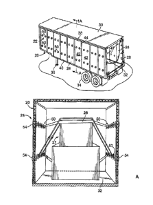
FIG. 1 is a perspective view of a trailer having a plurality of the hold down
assemblies which incorporate the features of the present invention; the hold
down assemblies
are mounted on the sidewalls of the trailer;
FIG. lA is an end view of the cargo compartment shown in FIG. 1 in which
cargo is stabilized by belts whose ends are anchored by the hold down
assemblies;
FIG. 2 is a perspective view of one of the hold down assemblies before
installing into the trailer;
2
CA 02953523 2017-01-03
54534-20D1
FIG. 3 is a rear elevational view of the hold down assembly;
FIG. 4 is a cross sectional view along line 4-4 of the hold down assembly of
FIG. 3, and also shows a portion of the sidewall of the trailer;
FIG. 4A is an enlarged view of a portion of the hold down assembly shown in
FIG. 4, with the portion of the sidewall of the trailer removed;
FIG. 5 is a rear elevational view of a plate assembly of the hold down
assembly;
FIG. 6 is a side elevational view of the plate assembly shown in FIG. 5;
FIG. 7 is a front elevational view of a cover of the hold down assembly;
FIG. 8 is a cross sectional view along line 8-8 of the cover of FIG. 7;
FIG. 8A is an enlarged view of a portion of the cover shown in FIG. 8;
FIG. 9 is a rear elevational view of the hold down assembly with adhesive
thereon and ready for mounting to a sidewall of a trailer;
2a
CA 02953523 2017-01-03
WO 2009/058762 PCT/US2008/081429
FIG. 10 is a side elevational view of a portion of a sidewall of the trailer
showing a first
embodiment of an aperture therethrough; and
FIG. 10A is a side elevational view of a portion of .a sidewall of the trailer
showing a
second embodiment of an aperture therethrough.
3
CA 02953523 2017-01-03
WO 2009/058762 PCT/US2008/081429
DETAILED DESCRIPTION OF THE PREFERRED EMBODIMENT
While the invention may be susceptible to embodiment in different forms, there
is shown
in the drawings, and herein will be described in detail, specific embodiments
with the
understanding that the present disclosure is to be considered an
exemplification of the principles
of the invention, and is not intended to limit the invention to that as
illustrated and described
herein.
A hold down assembly 50 is provided for use in connection with the sidewalls
24 of a
trailer 20. The hold down assembly 50 is used to secure cargo 27 within the
trailer 20.
The trailer 20 connects to a tractor (not shown) by conventional means, such
as a fifth
wheel assembly. The trailer 20 includes a body 22 formed from a pair of
rectangular sidewalls
24, a front wall (not shown), rear doors 28, a top panel or roof 30, and a
floor 32. The floor 32 is
supported by a conventional rear undercarriage assembly 34 and a landing gear
36. The roof 30
and an upper portion of the sidewalls 24 are secured to a top rail 38, and the
floor 32 and a lower
portion of the sidewalls 24 are secured to a bottom rail 40.
As shown in the drawings, each sidewall 24 includes a plurality of vertical
upstanding
composite side panels 42 joined together by a joint configuration 44. Each
composite panel 42
includes a core member 43 sandwiched between an outer thin skin 45a and an
inner thin skin 45b
and bonded thereto by a suitable known adhesive or other like means. The outer
skin 45a and the
inner skin 45b may be formed of metal, preferably aluminum or steel, and can
range in thickness
(such as 0.013 inches to 0.026 inches for steel skins and 0.050 inches for
aluminum skins) or
may be a thin composite material and can range in thickness (such as 0.026
inches). It is to be
understood that other thicknesses may be used as required by the application.
Typically, each
composite panel 42 is four feet in width, but can be longer or shorter
depending on the
application. At least two panels 42 are joined together to form the sidewall
24 of the body 22.
The core member 43 is made of some type of compressible non-metal material,
preferably
thermoplastic, such as polypropylene or high density polyethylene.
Alternatively, the sidewall 24
can be formed of a continuous sheet of composite material, or the sidewall 24
can be formed of
aluminum or fiberglass plates and posts, or any other known sidewall
structure.
A plurality of apertures 47 are provided through the sidewalls 24 at
predetermined
4
CA 02953523 2017-01-03
WO 2009/058762 PCT/US2008/081429
positions, and as shown in FIGS. 1 and 4, a hold down assembly 50 is mounted
at each aperture
47. As shown in FIGS. 2-4, the hold down assembly 50 includes a plate assembly
52 and a cover
54.
The plate assembly 52 is best shown in FIGS. 5 and 6 and includes a plate 56,
locating
fingers or lances 58, a mounting bracket 60 and a hold down 62. The plate
assembly 52 is
formed of metal. The plate 56 is galvanized. As shown, the plate 56 is
generally disc-shaped,
however, it is to be understood that the plate 56 can be provided in a variety
of shapes, such as,
for example, square, rectangular, or triangular.
The plate 56 includes an interior surface 64, an exterior surface 66 and a
peripheral edge
68. The perimeter of the plate 56 is larger than the perimeter of the aperture
47 in the sidewall 24
to which the plate assembly 52 is mounted. The locating fingers 58 are equally
radially spaced
from a center of the plate 56. The locating fingers 58 extend perpendicularly
from the interior
surface 64 of the plate 56. The locating fingers 58 are formed by punching
through the plate 56
to form a tab which remains attached to the plate 56 and bending the tab such
that the tab is
perpendicular to the remainder of the plate 56. Thus, an aperture 59 is
associated with each
locating finger 58. The locating fingers 58 are spaced from the center of the
plate 56 such that
the locating fingers 58 lie within the perimeter of the aperture 47 through
the sidewall 24.
The mounting bracket 60 is provided at the center of the interior surface 64
of the plate
56. As shown, the mounting bracket 60 is generally rectangularly-shaped. The
mounting bracket
60 includes first and second side portions 70, 72 and a center portion 74. The
first and second
side portions 70, 72 lay flat against the interior surface 64 of the plate 56.
The center portion 74
extends between the two end portions 72 and is spaced away from the interior
surface 64 of the
plate 56 to form a tunnel. The mounting bracket 60 is preferably mounted to
the plate 56 using
rivets 76. The head of each rivet 76 can be positioned on the surface of the
mounting bracket 60,
or can be countersunk into the mounting bracket 60 such that it is flush with
the mounting
bracket 60, depending on the dimensions of the mounting bracket 60 and the
heads of the rivets
76. The tail of each rivet 76 may extend beyond the exterior surface 66 of the
plate 56, or the tail
of each rivet 76 may be countersunk into the plate 56 such that it is flush
with the plate 56,
depending on the dimensions of the plate 56 and the tails of the rivets 76. If
the tail of each rivet
CA 02953523 2017-01-03
WO 2009/058762 PCT/US2008/081429
76 extends beyond the exterior surface 66 of the plate 56, the distance at
which each tail is proud
of the plate 56 is minimized in order to minimize the exterior profile of the
plate assembly 52.
As shown, the hold down 62 is formed as a D-ring with a base portion '63 and
an arcuate
portion 65. The base portion 63 is positioned under the center portion 74 of
the mounting
bracket 60 to secure the hold down 62 to the plate 56. The hold down 62 can
pivot relative to the
mounting bracket 60. It is also to be understood that the hold down 62 can
take a variety of
forms, such as a loop or a grab hook.
The cover 54 of the hold down assembly 50 is shown in FIGS. 7 and 8. The cover
54
includes an interior side 80, an exterior side 82, and a peripheral edge 84.
The material from
which the cover 54 is formed is selected to be the same material from which
the outer skin 45a of
the trailer sidewall 24 is formed and therefore, the color of the cover 54 is
the same as the outer
skin 45a of the trailer sidewall 24. The cover 54 does not have any apertures
therethrough to
= prevent the passage of water therethrough and to provide a uniform look
on the exterior surface
for decals. As shown, the cover 54 includes a centrally located circular
button portion 86, a
circular transition portion 87 extending radially outwardly from the button
portion 86, and a plate
portion 88 extending radially outwardly from the button portion 86 to the
peripheral edge 84.
The transition portion 87 angles relative to the button portion 86 and the
plate portion 88, and the
button portion of the cover 54 are parallel to each other.
As best shown in FIG. 8A, an outer edge portion 83 of the cover 54 proximate
to the
peripheral edge 84 is curved. The interior side 80 of the cover 54 defines a
cavity 85. An inner
portion 85a of the cavity 85 is provided by the button portion 86, a middle
portion 85b of the
cavity 85 is provided by the plate portion 88, and an outer portion 85c of the
cavity 85 is
provided by the outer edge portion 83. As best shown in FIG. 4A, the diameter
of the cover 54 is
selected such that the diameter of the cover 54 at the peripheral edge 84 is
larger than the
diameter of the plate assembly 52 at the peripheral edge 68. In addition, the
diameter of the
button portion 86 of the cover 54 is sufficiently sized such that inner
portion 85a of the cavity 85
accommodates the tails of the rivets 76. If the tails of the rivets 76 are
countersunk into plate 56,
then the button portion 86 of the cover 54 is eliminated.
The cover 54 is adhesively mounted to the exterior surface 66 of the plate
assembly 52 by
6
CA 02953523 2017-01-03
WO 2009/058762 PCT/US2008/081429
a bead of adhesive that is applied to the interior side 80 of the cover 54
proximate to the
peripheral edge of the plate portion 88: The bead of adhesive is applied such
that it is radially
outward of the of the apertures 59 and inside of the outer portion 85c of the
cavity 85 provided
by the outer edge portion 83. The cover 54 is aligned with the plate assembly
52 such that the
inner portion 85a of the cavity 85 is aligned with the tails of the rivets 76
and the middle portion
85b of the cavity 85 is aligned with the plate 56, The cover 54 is then bonded
to the plate
assembly 52 by the application of pressure.
Thereafter, the hold down assembly 50 is ready to be mounted to the sidewall
24. When
mounted to the sidewall 24, the plate 56, the button portion 86 and the plate
portion 88 are
generally parallel to the exterior surface of the trailer sidewall 24. The
outer edge portion 83 of
the cover 54 provides a transition between the exterior surface 82 of the
cover 54 and the
sidewall 24 of the trailer 20, and the peripheral edge 84 of the cover 54
generally abuts against
the outer surface of the panel 24. The diameter of the cover 54 is selected
such that when placed
over the plate assembly 52, the peripheral edge 84 of the cover 54 extends
beyond and curves
over the peripheral edge 68 of the plate 56.
The location and quantity of hold down assemblies 50 to be mounted to the
sidewalls 24
is determined by the customers needs and desires. In addition, the position of
the hold down
relative to the plate assembly 52 is determined by the customers needs and
desires. An aperture
47 is provided through the sidewall 24 for each hold down assembly 50 to be
mounted.
As best shown in FIGS. 2 and 9, a bead of adhesive 90 is provided on the
interior surface
64 of the plate 56. The adhesive 90 is spaced from the peripheral edge 68 of
the plate 56 and
radially outward of the mounting fingers 58 and apertures 59 of the plate 56.
Theplate assembly
52 is positioned over the aperture 47 of the sidewall 24 such that the
locating fingers 58 extend
into the aperture 47. The locating fingers 58 center the plate assembly 52
relative to the aperture
47 and the radial orientation of the plate assembly 52 can be selected as
desired by the customer.
Upon proper placement and orientation of the plate assembly 52, the plate
assembly 52 is
mounted to the exterior surface of the sidewall 24 of the trailer 20 by
applying pressure to bond
the adhesive 90 with the exterior surface of the sidewall 24. When adhered to
the sidewall 24 of
the trailer 20, the hold down 62 extends into and may extend beyond the
aperture 47 in the
7
CA 02953523 2017-01-03
WO 2009/058762 PCT/US2008/081429
sidewall 24 and is accessible from the interior of the trailer 20. Any
adhesive 90 that is squeezed
during the application of pressure may fill the well created by the outer
portion 85c of the cavity
85.
The aperture 47 can be circular as shown in FIG. 10, or the aperture 47 can be
non-
circular, for example, the aperture 47 is octagonal as shown in FIG. 10A. If
the aperture 47 is
circular, after the locating fingers 58 are inserted therein, the plate
assembly 52 is rotated to a
desired position. If the aperture 47 is non-circular, the locating fingers 58
are inserted therein
such that the hold down 62 is in the desired orientation, and each locating
finger 58 contacts one
of the flats which form the surfaces of the non-circular aperture 47. If the
aperture 47 is non-
circular, the hold down assembly 50 cannot be rotated within the aperture 47
since the locating
finger 58 contacts the flat. This non-circular aperture 47 allows for a
greater uniformity in
orientation to be more easily achieved When mounting multiple hold down
assemblies 50.
As best shown in FIGS. 4 and 8, the hold down assembly 50 extends minimally
from the
exterior surface of the sidewall 24 and thus, provides a low profile which is
lower in profile than
the prior art. This low profile improves the aesthetics of the exterior
surface of the trailer
sidewall 24. Importantly, given the extremely low exterior profile of the hold
down assembly 50,
decals and painted logos, for example, can be applied to the exterior surface
of the sidewall 24
without substantial obstruction or substantial deformation of the decal or
logo. In addition,
because the sidewall 24 and the cover 54 are formed from the same material,
the sidewall 24 and
the cover 54 provide the same characteristics with respect to the paint used
to cover the sidewall
24 and/or the logo applied to the sidewall 24. Therefore, no differentiation
with respect to
absorption or color, for example, will be observed between the cover 54 and
the sidewall 24.
The bonding of the cover 54 to the plate assembly 52 and the plate assembly 52
to the sidewall
24 prevents water from flowing through the apertures 59 of the plate 56 and
into the interior of
the trailer 20.
In use, outside members, such as straps 26, are attached by known means to the
hold
downs 62 to secure cargo 27 within the trailer 20.
The hold down assembly 50 can be used to replace prior art hold down
assemblies used in
the prior art by removing the prior art hold down assembly from the trailer
and.replacing it with
8
CA 02953523 2017-01-03
4534-20
the hold down assembly 50. As a result, older trailers can be retrofitted with
the low-profile hold
down assemblies 50.
The hold down 62 is shown and described as being statically mounted to the
plate 56
using a mounting bracket 60 and rivets 76. Alternatively, the hold down 62
could be rotationally
= mounted to the plate 56 using a pin (not shown) which rotates relative to
the plate 56.
= It is to be understood that, if desired, the cover 54 can be directly
mounted to the sidewall
24 as opposed to the plate assembly 52 by providing the bead of adhesive to
the inner surface of
the outer edge portion 83 of the cover 54. It is also to be understood that
the plate assembly 52
can be mounted to the sidewall 24 using tape and the cover 54 can be mounted
to the plate
= assembly 52 using tape.
The cover 54 is sized to accommodate the plate assembly 52. More specifically,
the
button portion 86 of the cover 54 is provided to accommodate the tails of the
rivets used to
mount the hold down 62 to the plate 56 if the tails of the rivets are proud of
the plate 56.
Alternatively, the hold down 62 could be adhesively mounted to the plate 56 or
the hold down 62
could be mounted to the plate 56 by welding; in either case, the button
portion 86 of the cover 54
would not be necessary and the cover 54 would provide an even lower exterior
profile.
While preferred embodiments of the present invention are shown and described,
it is
envisioned that those skilled in the art may devise various modifications of
the present invention
without departing from the scope of the appended claims.
=
9