Note: Descriptions are shown in the official language in which they were submitted.
CA 2953545
MAN WAY COVER
PRIORITY APPLICATION
[0001] This application claims priority to U.S. Appl. No. 62/020,977
filed July 3,
2014.
BACKGROUND OF THE INVENTION
Field of the Invention
[0002] Certain embodiments disclosed herein relate generally to manway
cover
assemblies for railroad tank cars. The manway cover assemblies can also be
used to control
access to the interior of other types of tanks and structures.
Description of the Related Art
100031 The current industry standard design for manway cover
assemblies on
railroad tank cars involves bolting down a cover with a series of eye bolts,
many of the systems
have a large number of bolts, such as 6 or 8 bolts. The design is very old and
can result in
costly failures for operators. Failures of the manway cover assemblies can
result in daily fines
accruing for the railroad operator.
[0004] The bolt-down design was originally intended to be secured by a
hand
wrench and tightened carefully in a star pattern. Crews charged with attaching
the covers are
under time pressures, thus, they commonly use impact wrenches while also
ignoring the star
pattern sequence. Common problems result from setting torque limits improperly
and over
tighten the nuts. This leads to stripped, stretched or broken eye-bolts, as
well as deformed
covers. Ultimately, the result is failure of the seal and leakage at the cover
because of user
error.
SUMMARY OF THE INVENTION
[0005] Accordingly, there is a need in the art for improved manway
cover
assemblies for use with railroad tank cars, among other things. A manway cover
assembly
according to certain embodiments can overcome one or more issues with the
prior art. For
example, the manway cover assembly can quickly and effectively be sealed while
removing or
reducing the opportunity for user error.
- 1 -
Date Recue/Date Received 2021-08-13
CA 02953545 2016-12-22
WO 2016/004378
PCT/US2015/039097
[0006] In some
embodiments, a manway cover assembly can comprise a
cover, a strongback, and a ram. The strongback can comprise a threaded opening
and a
plurality of arms, each arm comprising a ledge. The ram can have a threaded
body, the
ram connected to the cover and the threaded body being positioned within the
threaded
opening of the strongback. The ram can be configured to change the
relationship between
the strongback and the cover as the ram rotates. The manway cover assembly can
be
configured to control access to an opening, each ledge of each arm configured
to move to
engage a structure surrounding the opening to move the manway cover assembly
to a
locked position, as rotation of the ram forces the strongback away from the
cover until
each ledge engages the structure.
[0007] According to
some embodiments, a manway cover assembly can
comprise a frame, a cover, a strongback, and a ram. The frame can define an
opening and
comprise a flange. The cover can be hingedly attached to the frame and thereby
configured to move between a first position spaced away from the opening and a
second
position covering the opening. The strongback can comprise a threaded opening
and a
plurality of arms, each arm comprising a ledge. The ram can have a threaded
body and an
end having a spherical surface. The spherical surface can be rotatingly
connected to the
cover and the threaded body can be positioned within the threaded opening of
the
strongback and configured to change the relationship between the strongback
and the
cover as the ram rotates. The manway cover assembly can be configured such
that when
the cover is in the second position covering the opening, each ledge of each
arm is
configured to move to engage the flange to move the manway cover assembly to a
locked
position, as rotation of the ram forces the strongback away from the cover
until each
ledge engages the flange.
[0008] According to
some embodiments, a manway cover assembly can
comprise a screw tensioning system, a frame defining an opening, and a cover.
The screw
tensioning system can comprise a tensioning arm with a slot and a ram having a
threaded
body. The tensioning arm can be engaged with the ram through the threaded
body. The
slot of the tensioning arm can be configured to slide onto the frame when the
cover is
positioned over the opening. The ram can be attached to the cover with a
rotatable joint
and configured such that rotation of the ram changes the relationship between
the cover
and the tensioning arm to lock or unlock the manway cover assembly. Locking
can occur
when turning the ram forces the cover into contact with the frame while
advancing the
-2-
CA 02953545 2016-12-22
WO 2016/004378
PCT/US2015/039097
tensioning arm away from the cover, the tensioning arm being fixed in place
with relation
to the frame because of the slot that engages the frame.
[0009] In some
embodiments, a manway cover assembly can be used for
selectively sealing an access passageway of a tank. The manway cover assembly
can
comprise a frame, a lid unit and a securing mechanism to secure the lid unit
with the
frame when the lid unit is in a closed position. The frame can comprise a
radially inner
surface, a radially outer surface, and an axial axis. A first end portion of
the frame can be
adapted to be joined with the tank. A second end portion is axially opposite
the first end
portion. The second end portion can have a radially inner edge and define an
opening.
The lid unit can be rotatably connected with the frame and moveable between an
open
position and a closed position. The lid unit can cover the opening of the
second end
portion of the frame in the closed position.
[0010] The lid unit
can comprise a cover with a flange having a radially-
outwardly opening groove and a sealing ring in the radially-outwardly opening
groove.
The flange can be received in the opening of the frame when the lid unit is in
the closed
position. The lid unit can be configured such that, when the lid unit is in
the closed
position, the sealing ring is radially compressed between a back surface of
the groove and
the radially inner edge of the second end portion of the frame, thereby
providing a sealing
connection between the lid unit and the frame. The securing mechanism can
comprises a
single bolt or multi-bolt system.
[0011] According to
some embodiments, a manway cover assembly can
comprise a conduit comprising a radially inner wall, an opening, and a
radially outer wall
with a plurality of connection points; a cover configured to couple with the
conduit, the
cover movable between open and closed positions; and a securing mechanism. The
cover
can comprise a plurality of recesses corresponding to the plurality of
connection points; a
flange configured to be received in the opening of the conduit when the cover
is in the
closed position, the flange comprising a groove with a back surface, the
groove opening
in a radially-outward direction; and a seal in the groove, the seal being
radially
compressed between the radially inner wall of the conduit and the back surface
of the
groove when the cover is in the closed position. The securing mechanism can
include a
plurality of eye bolts corresponding to the plurality of connection points,
one of each of
the eye-bolts connected with the conduit via one of the connection points, the
eye-bolts
-3-
CA 2953545
configured to engage with the recesses in the cover and to secure the cover
relative to the
conduit.
[0012] A method of manufacturing a manway cover assembly can include
one or
more of the following steps. Obtaining a frame comprising a radially inner
wall and a
passageway. Obtaining a lid unit comprising a cover and a flange, the flange
comprising a
radially outwardly opening groove. Installing a sealing ring in the radially
outwardly opening
groove. Connecting the lid unit with the frame. Rotating the lid unit relative
to the frame such
that the lid unit covers the passageway in the frame. Radially compressing the
sealing ring
between the radially inner wall of the frame and the groove. Securing the lid
unit relative to the
frame.
[0013] A method of using a manway cover assembly can inhibit leakage
from a
passageway of a tank. The manway cover assembly can comprise a lid unit and a
frame, the lid
unit comprising a cover and a flange, the flange comprising a radially
outwardly opening
groove, the frame comprising a radially inner wall and an opening. The method
can comprise
closing the rnanway cover assembly, wherein closing the manway assembly can
comprise:
moving the lid unit into engagement with the frame such that the flange is
received inside the
opening of the frame; covering the passageway of the tank with the lid unit;
radially
compressing the sealing ring between the radially inner wall of the frame and
the radially
outwardly opening groove; and forming an air-tight seal between the sealing
ring and the
frame. The method can further include securing the manway cover assembly,
wherein securing
the manway cover assembly can comprise: engaging a securing mechanism with at
least one of
the lid unit and the frame; and substantially immobilizing, with the securing
mechanism, the lid
unit relative to the frame when the tank is at about atmospheric pressure.
Pressurizing the tank
above atmospheric pressure can cause the lid unit to move upward, away from
the frame. This
can cause sliding of the sealing ring along the inner wall of the frame. The
method can further
include maintaining the air-tight seal between the sealing ring and the frame.
[0013A] Various embodiments of the claimed invention relate to a manway cover
assembly comprising: a frame defining an opening and comprising a flange; a
cover hingedly
attached to the frame and thereby configured to move between a first position
spaced away
from the opening and a second position covering the opening; a strongback
comprising a
- 4 -
Date Recue/Date Received 2021-08-13
CA 2953545
threaded opening and a plurality of arms, each arm comprising a ledge; and a
ram having a
threaded body and an end having a spherical surface, the spherical surface
rotatingly connected
to the cover, the threaded body positioned within the threaded opening of the
strongback and
configured to change the relationship between the strongback and the cover as
the ram rotates;
wherein, the manway cover assembly is configured such that when the cover is
in the second
position covering the opening, each ledge of each arm is configured to move to
engage the
flange to move the manway cover assembly to a locked position, as rotation of
the ram forces
the strongback away from the cover until each ledge engages the flange.
[00138] Various embodiments of the claimed invention also relate to a manway
cover assembly comprising: a screw tensioning system comprising: a tensioning
arm with a
slot; and a ram having a threaded body, the tensioning arm engaged with the
ram through the
threaded body; a frame defining an opening; a cover, wherein the slot of the
tensioning arm is
configured to slide onto the frame when the cover is positioned over the
opening and the ram is
attached to the cover with a rotatable joint and configured such that rotation
of the ram changes
the relationship between the cover and the tensioning arm to lock or unlock
the manway cover
assembly, locking occurring when turning the ram forces the cover into contact
with the frame
while advancing the tensioning arm away from the cover, the tensioning arm
being fixed in
place with relation to the frame because of the slot that engages the frame;
and a cap configured
to cover the ram in a fixed position with respect to the tensioning arm,
wherein the cap
comprises a tab and the ram comprises a ram slot, such that when the cap
covers the ram the tab
is within the rain slot to thereby prevent rotation of the ram.
[0013C1 Various embodiments of the claimed invention also relate to a manway
cover assembly comprising: a cover; a strongback comprising a threaded opening
and a
plurality of arms, each arm comprising a ledge; and a ram having a threaded
body, the ram
connected to the cover and the threaded body being positioned within the
threaded opening of
the strongback and configured to change the relationship between the
strongback and the cover
as the ram rotates; wherein, the manway cover assembly is configured to
control access to an
opening, each ledge of each arm configured to move to engage a structure
surrounding the
opening to move the manway cover assembly to a locked position, as rotation of
the ram forces
the strongback away from the cover until each ledge engages the structure.
- 4a -
Date Recue/Date Received 2021-08-13
CA 2953545
[0013D] Various embodiments of the claimed invention also relate to a manway
cover
assembly for selectively sealing an access passageway of a tank, the manway
cover assembly
comprising: a frame comprising: a radially inner surface, a radially outer
surface, and an axial axis;
a first end portion adapted to be joined with the tank; and a second end
portion axially opposite the
first end portion, the second end portion comprising a radially inner edge and
defining an opening;
a lid unit rotatably connected with the frame, the lid unit moveable between
an open position and a
closed position and covering the opening at the second end portion of the
frame in the closed
position, the lid unit comprising: a cover comprising a flange, the flange
comprising a radially
outwardly opening groove, the groove comprising a top surface defining a top
of the groove, a back
surface defining a back of the groove, and a bottom surface defining a bottom
of the groove, the
flange being received in the opening of the frame when the lid unit is in the
closed position; a
sealing ring positioned in the radially-outwardly opening groove; the lid unit
configured such that,
when the lid unit is in the closed position, the sealing ring is radially
compressed between the back
surface of the groove and the radially inner edge of the second end portion of
the frame, thereby
providing a sealing connection between the lid unit and the frame; and a
securing mechanism
configured to secure the lid unit with the frame when the lid unit is in the
closed position.
10013E1 Various embodiments of the claimed invention also relate to a manway
cover
assembly comprising: a conduit comprising a radially inner wall, an opening,
and a radially outer
wall with a plurality of connection points; a cover configured to couple with
the conduit, the cover
movable between open and closed positions, the cover comprising: a plurality
of recesses
corresponding to the plurality of connection points; a flange configured to be
received in the
opening of the conduit when the cover is in the closed position, the flange
comprising a groove with
a top surface defining a top of the groove, a back surface defining a back of
the groove, and a
bottom surface defining a bottom of the groove, the groove opening in a
radially-outward direction;
and a seal in the groove, the seal being radially compressed between the
radially inner wall of the
conduit and the back surface of the groove when the cover is in the closed
position; a securing
mechanism comprising a plurality of eye-bolts corresponding to the plurality
of connection points,
one of each of the eye-bolts connected with the conduit via one of the
connection points, the eye-
bolts configured to engage with the recesses in the cover and to secure the
cover relative to the
conduit.
10013F] Various embodiments of the claimed invention also relate to a method
of
manufacturing a manway cover assembly, the method comprising: obtaining a
frame comprising a
4b -
Date Recue/Date Received 2021-08-13
CA 2953545
radially inner wall and a passageway; obtaining a lid unit comprising a cover
and a flange, the
flange extending from a bottom surface of the cover and comprising a radially
outwardly opening
groove, a top surface defining a top of the groove, a back surface defining a
back of the groove, and
a bottom surface defining a bottom of the groove; installing a sealing ring in
the radially outwardly
opening groove: connecting the lid unit with the frame; rotating the lid unit
relative to the frame
such that the lid unit covers the passageway in the frame; radially
compressing the sealing ring
between the radially inner wall of the frame and the groove; and securing the
lid unit relative to the
frame.
10013G1 Various embodiments of the claimed invention also relate to a method
of using
a manway cover assembly to inhibit leakage from a passageway of a tank, the
manway cover
assembly comprising a lid unit and a frame, the lid unit comprising a cover
and a flange, the flange
comprising a radially outwardly opening groove, the groove comprising a top
surface defining a top
of the groove, a back surface defining a back of the groove, and a bottom
surface defining a bottom
of the groove, the frame comprising a radially inner wall and an opening, the
method comprising:
closing the manway cover assembly, wherein closing the manway assembly
comprises: moving the
lid unit into engagement with the frame such that the flange is received
inside the opening of the
frame; covering the passageway of the tank with the lid unit; radially
compressing a sealing ring
between the radially inner wall of the frame and the radially outwardly
opening groove; and
forming an air-tight seal between the sealing ring and the frame; securing the
manway cover
assembly, wherein securing the manway cover assembly comprises: engaging a
securing
mechanism with at least one of the lid unit and the frame; and substantially
immobilizing, with the
securing mechanism, the lid unit relative to the frame when the tank is at
about atmospheric
pressure; pressurizing the tank above atmospheric pressure; moving the lid
unit away from the
frame, wherein the lid unit moves away due to the pressure in the tank;
sliding the sealing ring
along the inner wall of the frame; and maintaining the air-tight seal between
the sealing ring and the
frame.
BRIEF DESCRIPTION OF THE DRAWINGS
100141
Various embodiments are depicted in the accompanying drawings for
illustrative purposes, and should in no way be interpreted as limiting the
scope of the inventions, in
which like reference characters denote corresponding features consistently
throughout similar
embodiments.
- 4c -
Date Recue/Date Received 2021-08-13
CA 02953545 2016-12-22
WO 2016/004378
PCT/US2015/039097
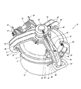
[0015] Figure 1 is a perspective view of a manway cover assembly for a
railroad car with the cover in a closed position.
[0016] Figure 2 is a side view of the manway cover assembly in an open
position.
[0017] Figure 3 shows a detail view of a hinged cover of the manway
cover
assembly in an open position.
[0018] Figure 4 is a partially exploded view of the manway cover
assembly.
[0019] Figure 5 illustrates a cross-section of the manway cover
assembly in a
closed position.
[0020] Figure 6 is a view of top of the manway cover assembly.
[0021] Figure 7 shows a tool engaged with a ram on the manway cover
assembly.
[0022] Figure 8 shows an adaptor for a tool, the adaptor engaged with
a ram
on the manway cover assembly.
100231 Figures 9-12 illustrate a method of closing the manway cover
assembly.
[0024] Figure 13 is a perspective view of another manway cover
assembly for
a railroad car with the cover in a closed position.
[0025] Figure 14 illustrates a cross-section of the manway cover
assembly.
[0026] Figure 15 is a partially exploded view of the manway cover
assembly.
[0027] Figure 16 is a side view of the manway cover assembly of Figure
13 in
an open position.
[0028] Figure 17 is a view of top of the manway cover assembly in a
closed
position as in Figure 14.
[0029] Figure 18 shows a tool engaged with a ram on the manway cover
assembly.
[0030] Figures 19-22 illustrate a method of closing the manway cover
assembly.
[0031] Figure 23 is a perspective view of another manway cover
assembly for
a railroad car with the cover in an open position.
[0032] Figure 24 shows a perspective view of the manway cover assembly
with the cover in a closed position.
[0033] Figure 25 is a cross-section of the manway cover assembly.
-5-
CA 02953545 2016-12-22
WO 2016/004378
PCT/US2015/039097
[0034] Figure 25A
is a detail of the cross-section taken along line 25A of
Figure 25.
DETAILED DESCRIPTION
[0035] A manway
cover is commonly used as an access door or hatch to the
interior of a tank, such as a railroad tank car. They can also be used to
access other types
of tanks and other types of structures. In broad terms, the manway cover
assembly can
have a tightening system, such as a screw tightening system and an attachment
system.
The attachment system can have a ledge configured to engage a flange that
surrounds an
opening. A cover can control access to the opening. The tightening system can
secure the
ledge to the flange and lock the cover over the opening. The embodiments are
described
herein with reference to tank cars, but it will be understood that the
described manway,
components and methods are not limited to this use. In addition, though the
manway may
be sized sufficient for a person to pass therethrough, this is not required.
[0036] Also
discussed herein are certain sealing systems that can be used on
different types of manway covers. The sealing systems can be used together
with single
bolt, or multi-bolt type tightening systems. It will be understood that
additional features
discussed herein can be used with or without the described sealing systems
and/or
tightening systems.
[0037] Figures 1
and 2 illustrate a manway cover assembly 10 for a railroad
car with the cover in respective closed and open positions. A manway cover
assembly 10
can provide quick access to the interior of a tank. A manway cover assembly 10
can
include a tightening system and an attachment or closure system. The
tightening system
can be a screw tightening system with a ram 8, though other types of
tightening systems
can also be used. The ram 8 can be a single bolt type tightening system.
[0038] As best seen
in Figures 2 and 3, the manway cover assembly 10 can
include a flange 2, a cover 4, a strongback 6, a ram 8, and a nozzle 12.
Engagement
between the cover 4 and either the flange 2 or the nozzle can control access
to the tank or
other structure through the manway cover assembly 10. The strongback 6 and ram
8 can
be used with the flange 2, cover 4 and nozzle 12 to secure the manway cover
assembly 10
in a locked position, as well as providing certain additional benefits as
described below.
For example, the ram 8 can be used to change the relationship between the
strongback 6,
the flange 2 and the cover 4 to increase or decrease pressure and/or the
distances between
these various components as will be described in more detail below.
-6-
CA 02953545 2016-12-22
WO 2016/004378
PCT/US2015/039097
[0039] According to
the various embodiments, the manway cover assembly 10
can include one or more additional features as described herein. It is to be
understood that
the illustrated manway cover assembly 10 includes each of the features
designated by the
numbers used herein. However, these features need not be present in all
embodiments.
[0040] A tank, such
as a railroad tank car, can have an opening to which a
manway cover assembly 10 can be attached to control access through the
opening. A
frame can be fixedly positioned with respect to the opening and the cover 4
can open and
close the opening by engaging the frame. The frame can include a flange 2 and
a nozzle
12. The flange 2 can be fixedly positioned with respect to the opening and the
cover 4 can
open and close the opening by engaging the frame (flange 2 and/or nozzle 12)
or some
other portion at or surrounding the opening. Typically, a manway cover
assembly 10 has
a nozzle 12 attached to the tank at the opening. The illustrated nozzle 12 is
a short
cylinder which can easily attach to an opening in a wall of a tank. The nozzle
12 can be
welded or otherwise secured to the tank and the flange can be attached to the
nozzle 12.
The flange 2 may be welded to the nozzle and may be a flange weldment 2 as
shown.
Other attachment methods can also be used. The illustrated nozzle 12 is
cylindrical,
though other shapes can also be used.
[0041] As will be
understood, the nozzle 12 can also define an opening. The
nozzle opening can be any number of different sizes. In some embodiments the
opening
can have a diameter of about 18 inches (in), 20 in, 22 in, or between 15 in
and 30 in.
100421 In some
embodiments, the flange 2 can have one or more slots 32. The
slots 32 can be used to facilitate engagement with the strongback 6 as will be
described in
more detail below.
[0043] In some
embodiments, the cover is a hinged cover 4. The cover 4 can
be connected directly to the hinge to keep the cover properly aligned with the
opening in
the tank car. The hinged cover 4 can be pivotally connected to a bracket 14
(Figures 2-3).
The bracket 14 can be attached to one or more of the flange 2, the nozzle 12
or some
other structure. In some embodiments, the bracket 14 can be directly attached
to the tank.
As will be understood by those of skill in the art, various features such as a
spring 16,
stops 18, and a handle 20 (Figure 1) can be used to control and/or assist with
the opening
and closing of the hinged cover 4.
[0044] A strongback
6 can be attached to the cover 4 through a ram 8 (Figures
4-5). The strongback 6 can be a type of secondary support member to the cover
4. In
-7-
CA 02953545 2016-12-22
WO 2016/004378
PCT/US2015/039097
particular, the strongback 6 can be used to help secure and lock the cover in
place, while
also providing for quick and easy release of the cover. The strongback 6 can
connect to
both the cover 4 and the flange 2. With the cover in place on the nozzle 12
and the
strongback engaged with both the cover and the flange, the ram 8 can then be
used to
force the strongback 6 and the cover 4 away from each other as shown in Figure
5.
Further, a sealing member 70, such as a gasket can be positioned between the
nozzle 12
and the cover 4. The sealing member 70 can be a sealing ring with any number
of
different profiles. The strongback 6 and ram 8 can help ensure that the cover
4 and nozzle
12 remain sealed even under high pressure.
[0045] In the
illustrated embodiment, the cover 4 has a boss 22 in the center
providing a centering pivot for the strongback 6. The ram 8 can have one end
positioned
inside the boss 22, while the other end is threadedly connected to the
strongback 6.
Rotation of the ram 8 can result in the strongback 6 moving either towards or
away from
the cover as illustrated by the double-headed arrows. The ram 8 can be
configured to
rotate in place with respect to the cover. Inside the boss 22 a spherical
contact surface 24
can match a spherical contour of the threaded ram 8 to form a rotatable joint.
This can
facilitate rotation of the ram while reducing friction.
[0046] It will be
understood that the illustrated arrangement of the strongback,
ram and cover can be varied in many ways. For example, in some embodiments,
the ram
can be positioned off-center, the ram can be received within the cover without
a boss,
and/or the cover can be threadedly connected to the ram instead of the
strongback. In
addition, the matching spherical surfaces 24 of the ram and boss can have
other shapes.
For example, the ram end can be a radially extending protrusion or disk shape.
As
another example, the ram can have a ball end and the boss and/or cover can
have a
corresponding socket. With a spherical and/or ball surface, the ram may be
provided with
some angular movement, such as to tilt one side of the strongback 6 slightly
downwards
or upwards.
[0047] With
continued reference to Figures 4-5, the ram can be secured within
the cover 4 and/or boss 22 with a separate plate 26. The plate 26 can be a
bolted flange on
the top surface (illustrated), a snap ring or other system to maintain the end
of the ram
within the boss and/or cover.
[0048] In addition
to providing a pivot surface (and potentially centering for
the strongback 6), the cover 4 can also provide rotation limiting stops 28, 30
(Figures 1 &
CA 02953545 2016-12-22
WO 2016/004378
PCT/US2015/039097
4). The rotation limiting stops can control the open and closed positions of
the
strongback during operation of the manway cover assembly 10 as will be
described in
more detail below. Additionally, the closed stop 30 is illustrated with a
flange, or tab,
with a hole 34 that can align with a similar tab with a hole 36 on the
strongback 6. When
the strongback 6 is in the closed position, the holes 34, 36 in these tabs can
accept a
security sealing tag or other security or locking device to prevent the manway
cover
assembly 10 from being opened. In some embodiments, the open stop 28 can have
a
similar tab and hole to receive a security or locking device.
[0049] The
strongback 6 can include one or more arms 38 as best seen in
Figures 1 and 4. In the illustrated embodiment, the strongback includes three
arms 38,
though one, two, four or more arms could be used. The arms 38 can extend the
required
distance to another surface for securing the arms with respect to this
surface. For
example, the arms 38 can extend beyond the outside diameter of the cover 4 for
engagement with the nozzle 12 and/or flange weldment 2. The arms can include
one or
more engagement features 40, such as the slots 40. The slots 40 are shown at
the end of
the arms, though it will be understood that they can also be positioned
elsewhere on the
arm. The slots 40 on the arms can be sized to engage the flange 2. Thus, the
slots 40 can
be as wide as the flange is thick. In some embodiments the slots can be wider
than the
thickness of the flange. This can facilitate attachment of the arms to the
flange, as well as
provide a pressure relief safety feature.
[0050] The flange 2
can also have one or more slots 32 that can facilitate
attachment of the arms 38 of the strongback 6 to the flange. The arms 38 with
corresponding slots 40 can be positioned at the slots when the cover 4 is
"open," i.e. the
cover is on the flange but not locked (Figure 10). The arms can then be
rotated so that the
slots 40 of the arms engage the flange 2 (Figures 11-12).
[0051] Returning to
Figure 5, it can be seen that the slots 40 have top, bottom
46 and side surfaces. The width of the slot 40 is defined by the distance
between the top
and bottom surfaces. In some embodiments the slot does not have a clearly
defined top
and/or side surface. For example, the top and/or side surface(s) can be angled
and may
more clearly be part of the arm itself The bottom surface 46 can be configured
to engage
a bottom 48 of the flange 2 and may be a ridge or ledge 46 extending from the
arm. In
addition, it is not required that the flange, slot, or ledge be flat,
parallel, or horizontal
surfaces ¨ other shapes, angles, and configurations can be used.
-9-
CA 02953545 2016-12-22
WO 2016/004378
PCT/US2015/039097
[0052] As shown,
the arms 38 can also include one or more support ribs 42. In
addition, the cover 4 and strongback 6 can be cast or fabricated components.
[0053] The
strongback 6 can also include an opening, such as a threaded
opening 44 to engage the ram 8. The opening 44 can be centered on the
strongback as
shown, but can also be located elsewhere. The strongback 6 can connect to the
cover 4
through the ram 8. The opening 44 can be a centering and positioning feature
for the
strongback 6. This configuration can also provide some shielding from outside
dirt and
debris. In addition, the slightly convex shape of the various components,
including the
cover and strongback can further allow debris (dirt, snow, ice) to fall off.
[0054] The ram 8
can be cast, forged or fabricated. As shown, the ram 8 has a
threaded portion 50 and a flanged spherical end 24 that matches the contour of
the center
boss 22 on the cover 4. The spherical contact between the ram 8 and cover 4
can allow for
increased contact surface, centering the clamping force and can allow for
variations in the
angle of contact. The body 50 of the ram can be threaded to match the thread
in the
strongback opening 44. This can allow for application of a clamping force as
the distance
between the strongback and the cover is increased.
[0055] A drive end
of the ram 8 has a bearing surface 52 as shown in Figure 6.
The bearing surface 52 can be a socket 52 (shown), outer flats, or other
surface to be
engaged by a tool for rotating or otherwise moving the ram. The socket 52 can
be a
recessed spline 52, a square drive, a slot, hex, Allen, Philips, etc. In some
embodiments,
the bearing surface 52 is configured for applying rotational force to the ram
during
operation of the manway cover assembly 10. In some embodiments the bearing
surface 52
can be a non-standard surface to limit operation to only certain tools. For
example, a
recessed drive socket 52 can restrict rotation of the ram 8 such that only
tools designed
for the application can open and close the manway cover assembly 10.
[0056] Figure 7
shows a tool 54 engaged with the socket for rotating the ram.
The tool 54 can have a shape corresponding with that of the socket and one or
more arms
to facilitate movement of the ram. In addition, the tool can be a specially
designed wrench
for properly torqueing the ram. Figure 8 shows an adapter 56 that can be
engaged by
another tool. The adapter 56 is shown with a square socket drive, but may
include any of
a number of different bearing surfaces.
[0057] The ram 8
can be relatively large in size. For example, the ram can
have a diameter of 2 to 3 inches. This large size can also allow for a large
socket 52. This
-10-
CA 02953545 2016-12-22
WO 2016/004378
PCT/US2015/039097
large size of the ram and/or the socket can provide certain advantages. For
example, it
can make the system more robust and can also make it less likely to be
tampered with
because of size tool needed to rotate the ram. The large size can also help
facilitate
centering of the strongback. In some embodiments, the diameter of the ram is
between
10% and 20% of the diameter of the cover. In some embodiments, the diameter of
the ram
is between 10% and 15% or between 15% and 20% of the diameter of the cover. In
some
embodiments, the cover can be between about 10 inches and 40 inches in
diameter, or
between 15 and 25 inches. In some embodiments the cover is 22.5 inches in
diameter and
is designed for use on a 20 inch diameter opening.
[0058] Returning to
Figure 6, it can also be seen that a cap 60 can be used to
cover the bearing surface 52 of the ram 8. The cap is preferably attached to
another
component of the manway cover assembly 10. As shown, the cap 60 is hingedly
attached
to the strongback 6 through a cap base 62. In other embodiments, the cap can
be
connected to the strongback 6 with a chain, rope, cord, clip, etc. The cap 60
can protect
the ram from debris, as well as limiting access to the bearing surface 52.
[0059] The
illustrated cap 60 is hinged to a cap base 62 providing a single
swinging open and closing action. The cap base 62 can be secured to the
strongback using
screws or other means to bond the two. In the closed position, the cap can be
locked or
secured in place. For example, the end of the cap opposite the hinge can have
a tab with
hole 64 that can be positioned adjacent one or more tabs with a hole 66 on the
base plate
or strongback. The holes can provide for locking the cap in place with a pin
and/or
security tag.
[0060] The cap 60
can also be used to limit rotation of the ram 8. The ram
and cap can have corresponding engagement surfaces 58, 68 such that when the
cap is
secured in place on the ram the ram cannot fully rotate. For example, as
shown, the top
end of the ram 8 has one or more key slots 58 cut on the outside surface. The
key slots
can be used with a cap locking device 68 to secure the ram 8 from rotating
inside of the
strongback 6. This can be particularly useful to deal with vibration during
transport of a
railcar. This locking feature can be the hinged cap used here or a simple lock
nut cap. In
addition, the cap 60 may not completely enclose the end of the ram 8.
[0061] The cap
locking device 68 can be a tab formed on the inside of the cap
60. The locking cap can provide anti-vibration rotation between the ram and
strongback
during transport of the railway tank car. The cap tab 68 also provides
additional
-11-
CA 02953545 2016-12-22
WO 2016/004378
PCT/US2015/039097
resistance to rotation between the cap and its base plate. The cap tab 68 can
be one or
more ribs designed to engage the slots 58 in the ram providing the anti-
rotation feature.
[0062] Returning now to Figures 4 and 5, assembly of components of the
illustrated manway cover assembly 10 will be discussed. The cover 4 is set on
the nozzle
12 and flange weldment 2. The hinge can then be connected at the bracket 14.
The ram 8
can then be positioned in the cover center boss 22 mating the spherical
surfaces 24. The
ram 8 can be retained with a flange or snap ring 26. This can keep the ram 8
positioned in
the cover 4 so that any lifting of the ram 8 will also lift the cover 4. The
strongback 6 can
be aligned on the ram. Rotating the ram 8 clockwise engages the mating threads
and the
strongback 6 is drawn toward the cover 4. One of the strongback arms 38 with
the slot 40
and/or ledge 46 is positioned between the open and closed stops 28, 30 on the
cover 4.
The cap 60 and base 62 can then be installed.
[0063] Operation of the Manway Cover Assembly
[0064] With reference to Figures 9-12, the operation of certain
embodiments
of manway cover assembly 10 will now be described. Looking to Figure 9, the
manway
cover assembly 10 is shown in a fully open position allowing for access into
the nozzle
12. If necessary, the strongback 6 can be rotated on the cover 4 counter
clockwise (CCW)
until one of the arms 38 contacts the open stop 28 on the cover. This will
help ensure that
the arms are in the proper location for attaching to the flange 2.
[0065] The cover 4 and strongback can be pivoted downward to contact
the
nozzle as shown in Figure 10. The cover 4 and strongback 6 are guided by the
hinge as
they are lowered onto the nozzle 12 and flange 2. It can be seen that the
strongback arms
38 are aligned with and positioned within the slots 32 on the flange 2. The
strongback
weight is supported by the ram 8 which is in contact through the spherical
mating surface
24 with the cover 4.
[0066] The strongback can then be rotated clockwise (CW) to engage the
flange 2. The CW motion can be made until the arm 38 contacts the close stop
30 on the
cover. This rotation engages the slots 40 of the strongback arms 38 to the
flange 2. The
cover 4 cannot be opened when in this position, as the ledge 46 of the
strongback arms 38
are under the flange 2.
[0067] Once in this position, the ram 8 can be fitted with a driving
tool 54, 56
and rotated CW (Figures 7-8). This action at the threaded engagement between
the ram 8
and the strongback 6 can lift the strongback 6 away from the cover 4. Rotation
can occur
-12-
CA 02953545 2016-12-22
WO 2016/004378
PCT/US2015/039097
until a set torque is achieved or until the ledges 46 at the slots 40 firmly
engage the flange
2 such that clearance between the flange and strongback arms is removed.
Additional CW
rotation of the ram 8 can force the cover to seal the interface with the
nozzle. A gasket
may further be included on the cover to help seal this interface. The force
applied to the
cover 4 can provide uniform pressure on the sealing and on the sealing gasket
if used.
Having the strongback 6 centered on the cover can facilitate even distribution
of forces.
[0068] Once tighten
as desired; the cap 60 can be flipped over or rotated to
cover the ram 8 as shown in Figure 12. When the cap includes a locking
feature, the ram
can be rotated such that one of the slots 58 is aligned with a tab 68 on the
cap. The cap 60
can then be closed to position the tab 68 within the slot 58. In some
embodiments, an
arrow (Figure 6) on the cap base 62 or strongback can indicate the ideal
position of the
slot 58 to facilitate engagement with the cap tab 68.
[0069] Locks and/or
security tags can be connected to the manway cover
assembly 10 once fully closed and locked, or at other times during the
operation. A lock,
pin, or security tag can be connected to the tab with hole 64 on the cap 60
and the
corresponding tabs with a hole 66 on the base plate or strongback. Similarly,
a lock, pin,
or security tag can be connected to the tab with hole 34, 36 on the cover and
strongback.
[0070] To open the
manway cover assembly 10, a method opposite that just
described can be employed. For example, any locks, pins or security tags can
first be
removed from the locking cap tabs 64, 66 and/or the strongback/cover mating
tab stops
30, 36. The locking cap 60 can be swung to the full open position allowing
access to the
ram driving feature. Using a ram driving tool the ram is rotated CCW until the
strongback
is loosely floating. The strongback is still engaged with the nozzle flange
even though the
force pushing the cover and gasket into the nozzle is removed. Advantageously,
if the
tank had been under internal pressure, the cover is held from blowing off by
the engaged
strongback but allowed to vent with a broken seal. The strongback can then be
rotated
CCW until it engages the open stop on the cover and the cover is then free to
be lifted.
100711 It will be
understood that at times, the manway cover assembly 10 can
be used in a situation where the tank contents are sticky. In addition, the
content may be
held under low pressure, the tank may not be pressurized at all. Some of the
sticky
contents may get on the frame, as at the opening to the nozzle, or they may
get on the
cover, such as on a gasket or seal on the cover. In currently available
designs, these types
of situations may require the cover to be pried off in order to be opened.
Beneficially, the
-13-
CA 02953545 2016-12-22
WO 2016/004378
PCT/US2015/039097
manway cover assembly 10, according to some embodiments, can loosen the cover
without or reducing the need for additional tools to pry it off. In the
typical operation,
after rotating the ram 8 CCW to loosen the strongback 6 and the clamping
force, the
strongback 6 can be rotated and the cover 4 opened. But, where the cover 4 is
stuck to the
frame, continued CCW rotation of the ram 8, before rotating the strongback 6,
can force
the cover open. This is because continued rotation of the ram, while the cover
remains in
contact with the frame, causes the strongback arms 38 to engage the top
surface of the
flange 2. Thus, for example, the top surface of the slot 40 can engage the top
surface of
the flange 2 and mechanically pull or lift the cover away from the nozzle. In
other
embodiments, a portion of the arms 38 can contact the top surface of the
flange. In view
of the above, it will be understood that to facilitate this feature, the
strongback and cover
can be sized and contoured such that when the arms and or slot contact the top
of the
flange 2, there is sufficient space between the strongback and the cover to
allow the cover
to move upwards closer to the strongback.
[0072] In some
embodiments, a manway cover assembly 10 can have a
tightening system that it is all on one side of a cover. The tightening system
can be a
screw tensioning system. The manway cover assembly 10 can further include an
attachment system having a ledge 46 configured to engage a flange 2 that
surrounds an
opening, the manway cover assembly 10 configured to control access to the
opening.
[0073] According to
some embodiments, a manway cover assembly 10 can
have a screw tensioning system, a frame and a cover. The screw tensioning
system can
have a tensioning arm with a slot that slides onto a frame when the cover is
positioned at
the frame. The screw tensioning system can include a ram that attaches to the
cover with
a rotatable joint. The ram can also be threadedly attached to the tensioning
arm so that
rotation of the ram changes the relationship between the cover and the
tensioning arm to
lock or unlock the manway cover assembly 10. For example, when locking the
manway
cover assembly 10, turning the ram can force the cover into contact with the
frame while
advancing the tensioning arm away from the cover, the tensioning arm being
fixed in
place with relation to the frame because of the slot that engages the frame.
[0074] Figures 13-
22 illustrate another embodiment of manway cover
assembly 10'. Numerical reference to components is the same as previously
described,
except that a prime symbol (') has been added to the reference. Where such
references
occur, it is to be understood that the components are the same or
substantially similar to
-14-
CA 02953545 2016-12-22
WO 2016/004378
PCT/US2015/039097
previously-described components. It should be understood that the illustrated
manway
cover assembly 10' includes each of the features designated by the numbers
used herein.
However, as emphasized repeatedly herein, these features need not be present
in all
embodiments.
[0075] Comparing
Figures 13-22 with Figures 1-12 certain similarities
between the manway cover assemblies will be readily apparent. For example, it
will be
understood that the flange 2', cover 4', strongback 6', ram 8', and a nozzle
12' can all
function in substantially the same way as previously described. Engagement
between the
cover 4' and either the flange 2' or the nozzle can control access to the tank
or other
structure through the manway cover assembly 10'. Rotation of the ram 8' can
result in the
strongback 6' moving either towards or away from the cover 4'. This can create
the
necessary forces to secure the manway cover assembly 10' in the locked
position, while
also facilitating opening of the manway cover assembly 10'.
[0076] There are
also a number of differences between the manway cover
assemblies of Figures 13-22 and Figures 1-12. Certain of these differences are
highlighted
below. For example, it can be seen that the arms 38' include two support ribs
42'. The
rotation limiting stops 28', 30' have also been changed. The rotation limiting
stops can
control the open and closed positions of the strongback during operation of
the manway
cover assembly 10'. The closed stop 30' is illustrated as a flange, or tab,
with a hole 34'
that can align with a hole 36' on the support rib 42', rather than on a
separate tab on the
strongback 6'. When the strongback 6 is in the closed position, the holes 34',
36' can
accept a security sealing tag or other security or locking device to prevent
the manway
cover assembly 10' from being opened.
[0077] The open
stop 28' has also been modified. In addition to serving as an
open stop, it can also provide a pressure release safety feature. The pressure
release safety
feature 28' can allow the cover 4' to open a small amount, while preventing it
from
becoming completely open without actuation by a user. This can help to allow a
controlled pressure release from inside the hatch. This can also prevent a
pressure release
from potentially hurting someone or damaging the hatch. As can be seen, the
pressure
release safety feature can be a latch 28' such as a gravity fed hook that is
biased towards a
locked position. If moved upwards, the hook 28' can engage the flange 2' to
prevent the
cover from fully opening. This can for example, prevent the cover from popping
open
when there is large pressure different between the contents inside the tank
and the
-15-
CA 02953545 2016-12-22
WO 2016/004378
PCT/US2015/039097
atmosphere. It will be understood that any number of different mechanisms can
be used
as the pressure release safety feature.
[0078] Referring to
Figure 13, it can also be seen, that the manway cover
assembly 10' can include one or more locks 72. A cross-section of a lock 72
can be seen
in Figure 14. A lock 72 can include a pin 74 and a spring 76 to bias the pin
74 to a locked
position. A handle 78 can be located on one end of the pin to disengage the
opposite end
80 from a hole 82, 84, 88, groove, slot 58', etc. The lock 14 in Figure 14 is
shown on an
arm 38 of the strongback 6, but it will be understood that the lock can be
located in any
number of different places.
[0079] As will be
understood, a lock 72 on the strongback 6' can be used to
lock the strongback in position with respect to the cover 4' and/or flange 2'
/ nozzle 12'.
The lock 72 can be used to prevent the strongback 6' from rotating, in
particular while
opening or closing the cover 4'.
[0080] Looking now
to Figure 15, holes 82, 84 can be seen respectively on the
flange 2' and the cover 4'. The end 80 (Figure 14) of the lock 72 can engage
with the hole
82 on the flange 2' in one position and with a hole 84 on the cover 4' in
another position.
In still another position, the end 80 of the lock 72 can be unengaged with any
holes to
allow for movement of the strongback 6' with respect to the cover 4' and/or
flange 2' /
nozzle 12'. For example, when the manway cover assembly 10' is in an unlocked
position,
(Figure 16) the spring-loaded pin lock 72 can engage the hole 84 on the cover.
When the
manway cover assembly 10' has been moved down to cover the nozzle opening and
then
rotated, the spring-loaded pin lock 72 can engage the hole 82 on the flange
(Figure 17). It
will be understood that the spring-loaded pin lock 72 can engage other parts
of the
manway cover assembly 10'. For example, in some embodiments the lock 72 can
engage
with different portions of the cover in either position.
[0081] In some
embodiments, the cover 4' can include a protrusion 90
(Figures 15 & 17). The protrusion 90 can include the hole 84. The protrusion
90 can be
sized to fit within one of the slots 32' on the flange 2'. A portion of the
protrusion 90 with
the hole 84 can be flush with, or slightly above or below the flange 2' when
the cover 4' is
in the closed position. In this way actuation of the handle 78 to unlock the
lock can be
similar in the various positions. As shown, the protrusion 90 is an "L" shaped
protrusion
that extends downwards and then outwards, but it will be understood that the
protrusion
can have any number of different shapes and configurations.
-16-
CA 02953545 2016-12-22
WO 2016/004378
PCT/US2015/039097
[0082] A number of
different locks 72 can be included on a manway cover
assembly. A second lock 72 is shown configured to lock the cap 60' in place.
Continuing
to refer to Figures 15 & 17, a lock 72 is shown configured to secure the cap
60' to the cap
base 62'. The cap base 62' can be fixed in position to the arms 38'. The cap
60' and lock
72' can be adjusted based on the position of the ram 8' and the bearing
surface 52' of the
ram 8'. The cap 60 can protect the ram from debris, as well as limiting access
to the
bearing surface 52'.
[0083] As has been
discussed previously, a drive end of the ram 8' has a
bearing surface 52'. The bearing surface 52' can be a socket 52' (shown),
outer flats, or
other surface to be engaged by a tool for rotating or otherwise moving the
ram. The
socket 52' can be a recessed spline 52, a square drive 52', a slot, hex,
Allen, Philips, etc.
The bearing surface 52' is used to apply rotational force to the ram during
operation of the
manway cover assembly 10'. In some embodiments the bearing surface 52' can be
a non-
standard surface to limit operation to only certain tools. For example, a
recessed drive
socket 52' can restrict rotation of the ram 8' such that only tools designed
for the
application can open and close the manway cover assembly 10'.
[0084] A cap 60'
can be used to cover the bearing surface 52' of the ram 8'.
The cap is preferably attached to another component of the manway cover
assembly 10'.
As shown in Figures 13 and 14, a cord 92 attaches the cap 60' to the
strongback 6'. In
other embodiments, the cap can be connected to the strongback 6' with a chain,
rope, clip,
etc. or can the hingedly or otherwise attached. The cord 92 can be secured to
any number
of different features on the strongback 6', such as a hole in the arm 38'
and/or support rib
42' (Figure 14). The lock 72 can further secure the cap in place over the ram
8'.
[0085] The
illustrated cap 60' is secured over the ram with the lock 72
engaging the cap base 62'. The cap base 62' can be secured to the strongback
using screws
or other means to bond the two. The cap base 62' can include a number of slots
58'
(Figure 15). The end 80 of the pin 74 of the lock 72 can engage with a slot
58' to lock the
cap 60' in place.
[0086] As has been
mentioned, the cap 60' can also be used to limit rotation of
the ram 8'. The ram and cap can have corresponding engagement surfaces, such
that when
the cap is secured in place on the ram the ram cannot fully rotate. For
example, as shown
in Figure 17, a cap locking device 68' can be sized to fit within the bearing
surface 52' of
the ram 8'. As shown, the cap locking device 68' can be a protrusion having a
profile that
-17-
CA 02953545 2016-12-22
WO 2016/004378
PCT/US2015/039097
matches the profile of the hole defined by the bearing surface 52', here both
being square.
Further, the lock 72 can lock the cap 60' to the cap base 62. The cap base has
a plurality
of slots 58' so that the lock can be engaged essentially independently of the
position of the
ram 8'. The lock 72 itself can rotate about the cap base 62' or be permanently
secured to
the cap 60'. For example, the lock 72 can be secured to the cap 60' at the
hole 88. If the
lock rotates about the cap base, it can be rotated to align with the hole 88
when the cap is
on the ram.
[0087] As will be
understood, pulling on the handle 78 can release the lock
from the slot 58'. The cap can then be removed from covering the ram. With the
cap
removed a tool 54' can engage the socket on the ram as shown in Figure 18.
[0088] Looking to
Figures 19-22, the manway cover assembly 10' can be
opened and closed substantially as described with the manway cover assembly 10
of the
prior embodiments with the addition of the actuation of the locks 72 and other
differences
some of which have been described above.
[0089] With the
manway cover assembly 10' in the closed position, the cover
4' can be sealed to the nozzle 12' in an airtight manner, this best seen in
the cross-section
of Figure 14. A gasket 70' on the cover 4' can engage with the wall of the
nozzle 12' to
form a seal. The gasket 70' can be a sealing ring such as an 0-ring as shown,
but can also
have other shapes and configurations. In some embodiments the gasket can be
made of an
elastomer such as TEFLON.
[0090] The cover 4'
can have a flange or ring 86 that extends downward from
the bottom of the cover. The ring 86 can include a radially-outwardly opening
groove or
side channel 94 in which the 0-ring 70' can sit. In some embodiments, the
inner end of
the nozzle can be machined to ensure a good seal with the 0-ring.
[0091] The gasket
70' can provide a lateral seal with the nozzle 12'. This
lateral seal can beneficially deal with increases in pressure within the tank
car. For
example, the high pressures in some tank cars can result in the cover rising
by upwards of
1/8 of an inch. This can be counteracted with high torque on the ram or bolt,
but even
then, there may be some rising of the cover. If the cover is not properly
secured, the seal
can break, causing leakage. A seal on the top of the nozzle may be broken if
the cover
rises up. The lateral seal shown in Figure 14 can maintain sealing engagement,
even in
some situations where the cover is not properly secured. A high pressure
within the tank
CA 02953545 2016-12-22
WO 2016/004378
PCT/US2015/039097
car can result in the cover rising with no effective change in the seal
between the cover
and the nozzle.
[0092] It will be
understood that any of the individual features described with
respect to Figures 13-22 can be used with the manway cover assembly 10 of
Figures 1-
12. For example, the pressure release safety feature 28 can be used instead of
or in
addition to the open stop 28. As another example, one or more spring-loaded
pin lock 72
could also be used on the manway cover assembly 10 of Figures 1-12.
[0093] Turning now
to Figures 23-25A another embodiment of manway cover
assembly 10" is shown. Numerical reference to components is the same as
previously
described, except that a double prime symbol (") has been added to the
reference. Where
such references occur, it is to be understood that the components are the same
or
substantially similar to previously-described components. It should be
understood that the
illustrated manway cover assembly 10" includes each of the features designated
by the
numbers used herein. However, as emphasized repeatedly herein, these features
need not
be present in all embodiments.
[0094] The manway
cover assembly 10" is a multi-bolt system. In the
illustrated embodiment, instead of a single bolt or ram 8, there are six eye
bolts 8". It will
be understood that the multi-bolt system can have any number of bolts such as
6, 8, 10,
and 12. Figures 23 and 24 show the manway cover assembly 10" in open and
closed
positions. In the cross-section of Figures 25 and 25A a sealing arrangement
similar to
that of Figure 14 is shown.
[0095] With the
manway cover assembly 10" in the closed position, the cover
4" can be sealed to the nozzle in an airtight manner. A gasket 70" on the
cover 4" can
engage with the wall of the nozzle 12' to form a seal. The gasket 70" can be a
sealing ring
such as an 0-ring as shown, but can also have other shapes and configurations.
[0096] The cover 4"
can have a flange or ring 86" that extends downward
from the bottom of the cover. The ring can be a separate piece secured to the
cover, but
can be also be cast or molded as the same piece. The ring 86" can include a
radially-
outwardly opening groove or side channel 94" in which the 0-ring 70" can sit.
It can also
be seen that the inner end of the nozzle has been machined to ensure a good
seal with the
0-ring along various heights of the seal. The machined surface can have a
surface finish
with a roughness average (Ra) of less than or equal to about 250 microinches
(6.35
micrometers). In some embodiments, it can be less than or equal to about 500
-19-
CA 02953545 2016-12-22
WO 2016/004378
PCT/US2015/039097
microinches, 400 microinches, 300 microinches, 200 microinches or 100
microinches.
For example, an inch or two of the end of the nozzle can be machined to ensure
a proper
seal with an 0-ring 1/8, 1/4, 1/2, 3/4 or 1 inch tall (i.e. diameter of the
profile). The
nozzle can be cast and an end mill can be used to finish the end of the nozzle
to provide a
smooth surface for engagement with the gasket 70". In some embodiments, the
nozzle 12"
can also include a chamfered or rounded end. This can help ensure that the
ring 86" can
fit within the nozzle 12". For example a radially outer beveled corner can be
configured to
aid in receiving the ring in the opening as the cover is moved from the open
position to
the closed position.
[0097] The gasket
70" can also extend outward from the ring 86". This can
allow for pressure inside the tank to act on the gasket as well as the cover.
This force
acting on the gasket can encourage the gasket to flatten out, thus increasing
the lateral
forces on the side of the nozzle and helping to ensure a strong seal is
maintained.
Preferably, the gasket is compressed only by the groove and the side wall of
the nozzle.
100981 As has been
explained, the gasket 70" can provide a lateral seal with
the nozzle 12". This lateral seal can beneficially deal with increases in
pressure within the
tank car. For example, the high pressures in some tank cars can result in the
cover rising
up by upwards of 1/8 inch (3 mm). This can be counteracted with high torque on
the ram
or bolt, but even then, there may be some rising of the cover. If the cover is
not properly
secured, the seal can break, causing leakage. Even if the bolts 8" are
initially properly
secured, they may come lose over time. A seal on the top of the nozzle may be
broken if
the cover rises up. The lateral seal shown can maintain sealing engagement,
even in some
situations where the cover is not properly secured. A high pressure within the
tank car can
result in the cover rising with no change in the seal between the cover and
the nozzle.
[0099] In some
embodiments, a manway cover assembly can be used for
selectively sealing an access passageway of a tank. The manway cover assembly
can
comprise a frame, a lid unit and a securing mechanism to secure the lid unit
with the
frame when the lid unit is in a closed position. The frame can comprise a
radially inner
surface, a radially outer surface, and an axial axis. A first end portion of
the frame can be
adapted to be joined with the tank. A second end portion is axially opposite
the first end
portion. The second end portion can have a radially inner edge and define an
opening.
The lid unit can be rotatably connected with the frame and moveable between an
open
-20-
CA 02953545 2016-12-22
WO 2016/004378
PCT/US2015/039097
position and a closed position. The lid unit can cover the opening of the
second end
portion of the frame in the closed position.
[0100] The lid unit
can comprise a cover with a flange having a radially-
outwardly opening groove and a sealing ring in the radially-outwardly opening
groove.
The flange can be received in the opening of the frame when the lid unit is in
the closed
position. The lid unit can be configured such that, when the lid unit is in
the closed
position, the sealing ring is radially compressed between a back surface of
the groove and
the radially inner edge of the second end portion of the frame, thereby
providing a sealing
connection between the lid unit and the frame.
[0101] In some
embodiments, when the lid unit is in the closed position, the
cover is configured to move axially away from the frame up to about 3 mm in
response to
pressure in the tank; and the sealing ring is configured to move axially with
the cover,
and to slide axially along and relative to the radially inner edge of the
second end portion
of the frame, thereby maintaining the sealing connection between the lid unit
and the
frame. In some embodiments, an endmost portion of the second end portion of
the frame
abuts with the cover without a resilient seal intervening axially
therebetween. In some
embodiments, the frame further comprises an intermediate portion between the
first end
portion and the second end portion, the intermediate portion having a radially
inner
surface with a first diameter; the flange of the cover of the lid unit further
comprises a
radially outer surface with a second diameter; the radially inner edge of the
second end
portion of the frame has a third diameter; and the first diameter is less than
the second
diameter, and the second diameter is less than the third diameter.
101021 According to
some embodiments, a manway cover assembly can
comprise a conduit comprising a radially inner wall, an opening, and a
radially outer wall
with a plurality of connection points; a cover configured to couple with the
conduit, the
cover movable between open and closed positions; and a securing mechanism. The
cover
can comprise a plurality of recesses corresponding to the plurality of
connection points; a
flange configured to be received in the opening of the conduit when the cover
is in the
closed position, the flange comprising a groove with a back surface, the
groove opening
in a radially-outward direction; and a seal in the groove, the seal being
radially
compressed between the radially inner wall of the conduit and the back surface
of the
groove when the cover is in the closed position. The securing mechanism can
include a
plurality of eye bolts corresponding to the plurality of connection points,
one of each of
-21-
CA 02953545 2016-12-22
WO 2016/004378
PCT/US2015/039097
the eye-bolts connected with the conduit via one of the connection points, the
eye-bolts
configured to engage with the recesses in the cover and to secure the cover
relative to the
conduit.
[0103] A method of
manufacturing a manway cover assembly can include one
or more of the following steps. Obtaining a frame comprising a radially inner
wall and a
passageway. Obtaining a lid unit comprising a cover and a flange, the flange
comprising a
radially outwardly opening groove. Installing a sealing ring in the radially
outwardly
opening groove. Connecting the lid unit with the frame. Rotating the lid unit
relative to
the frame such that the lid unit covers the passageway in the frame. Radially
compressing
the sealing ring between the radially inner wall of the frame and the groove.
Securing the
lid unit relative to the frame.
[0104] Some
embodiments of the method may further include one or more of
the following steps. Receiving the flange in the passageway of the frame.
Installing a
sealing ring in the radially outwardly opening groove by passing the sealing
ring over a
bevel on a radially outer corner of the flange. Machining the inner wall of
the frame.
Machining the inner wall of the frame can comprise machining the inner wall to
have a
surface finish with a roughness average (Ra) of less than or equal to about
250
microinches (6.35 micrometers). Rotating a ram to change a relationship
between a
strongback and the cover.
[0105] A method of
using a manway cover assembly can inhibit leakage from
a passageway of a tank. The manway cover assembly can comprise a lid unit and
a frame,
the lid unit comprising a cover and a flange, the flange comprising a radially
outwardly
opening groove, the frame comprising a radially inner wall and an opening. The
method
can comprise closing the manway cover assembly, wherein closing the manway
assembly
can comprise: moving the lid unit into engagement with the frame such that the
flange is
received inside the opening of the frame; covering the passageway of the tank
with the lid
unit; radially compressing the sealing ring between the radially inner wall of
the frame
and the radially outwardly opening groove; and forming an air-tight seal
between the
sealing ring and the frame. The method can further include securing the manway
cover
assembly, wherein securing the manway cover assembly can comprise: engaging a
securing mechanism with at least one of the lid unit and the frame; and
substantially
immobilizing, with the securing mechanism, the lid unit relative to the frame
when the
tank is at about atmospheric pressure. Pressurizing the tank above atmospheric
pressure
-22-
CA 2953545
can cause the lid unit away to move upward, away from the frame. This can
cause sliding of the
sealing ring along the inner wall of the frame. The method can further include
maintaining the
air-tight seal between the sealing ring and the frame.
101061
According to some embodiments, securing the rnanway cover assembly can
include tightening at least six eye-bolts. In some embodiments, the
pressurizing the tank above
atmospheric pressure comprises pressurizing the tank to at least about 100
psi. It will be
understood that the pressure inside the tank can depend on a number of
factors, including: the
contents and the temperature. A railway tank car can have an operating
pressure of 10-15 psi,
but is often more commonly around 35 psi.
[0107] A
railway tank car and therefore a manway cover assembly on a railway
tank car can be rated to withstand a maximum pressure of 165 psi with a safety
factor of 1.5 so
that the tank car is tested to 206 psi. Though this is standard in some
countries, it will be
understood that the various embodiments of manway cover assembly discussed
herein can be
rated to withstand and/or can be tested to withstand 140, 150, 165, 175, 190,
200, 210, 220,
230, or 250 psi. The manway cover assemblies can also be used with a high
pressure tank car
with a pressure rating of about 500 psi, or between 400-600 psi.
101081
The manway cover assemblies can be made of a number of materials, but are
preferably made of metal. The parts can be steel castings and/or welded in
some embodiment.
Additional details on materials, testing and other features of manway cover
assemblies can be
found in the Association of American Railroads (AAR), Manual of Standards and
Recommended Practices Section
Specification for Tank Car, Specification M-1002
(2014). The Specification M-1002 is referenced, including the Appendices, in
particular to
Appendix D and E on testing and design criteria.
101091
Although this invention has been disclosed in the context of certain preferred
embodiments and examples, it will be understood by those skilled in the art
that the present
invention extends beyond the specifically disclosed embodiments to other
alternative
embodiments and/or uses of the invention and obvious modifications and
equivalents thereof.
In addition, while a number of variations of the invention have been shown and
described in
detail, other modifications, which are within the scope of this invention,
will be readily
apparent to those of skill in the art based upon this disclosure.
- 23 -
Date Recue/Date Received 2021-08-13
CA 02953545 2016-12-22
WO 2016/004378
PCT/US2015/039097
It is also contemplated that various combinations or sub-combinations of the
specific
features and aspects of the embodiments may be made and still fall within the
scope of
the invention. Accordingly, it should be understood that various features and
aspects of
the disclosed embodiments can be combined with or substituted for one another
in order
to form varying modes of the disclosed invention. Thus, it is intended that
the scope of
the present invention herein disclosed should not be limited by the particular
disclosed
embodiments described above, but should be determined only by a fair reading
of the
claims that follow.
[0110] Similarly,
this method of disclosure, is not to be interpreted as
reflecting an intention that any claim require more features than are
expressly recited in
that claim. Rather, as the following claims reflect, inventive aspects lie in
a combination
of fewer than all features of any single foregoing disclosed embodiment. Thus,
the claims
following the Detailed Description are hereby expressly incorporated into this
Detailed
Description, with each claim standing on its own as a separate embodiment.
-24-