Language selection

Search

Patent 2953605 Summary

Third-party information liability

Some of the information on this Web page has been provided by external sources. The Government of Canada is not responsible for the accuracy, reliability or currency of the information supplied by external sources. Users wishing to rely upon this information should consult directly with the source of the information. Content provided by external sources is not subject to official languages, privacy and accessibility requirements.

Claims and Abstract availability

Any discrepancies in the text and image of the Claims and Abstract are due to differing posting times. Text of the Claims and Abstract are posted:

  • At the time the application is open to public inspection;
  • At the time of issue of the patent (grant).
(12) Patent: (11) CA 2953605
(54) English Title: APPARATUS AND METHOD TO MOVE PRESSURE VESSEL BETWEEN HORIZONTAL AND VERTICAL POSITIONS
(54) French Title: APPAREIL ET METHODE SERVANT A DEPLACER UN RECIPIENT SOUS PRESSION ENTRE DES POSITIONS HORIZONTALES ET VERTICALES
Status: Granted
Bibliographic Data
(51) International Patent Classification (IPC):
  • F16M 1/00 (2006.01)
  • E21B 15/00 (2006.01)
  • F16J 12/00 (2006.01)
  • E21B 7/02 (2006.01)
  • E21B 43/34 (2006.01)
(72) Inventors :
  • NAGGE, RORY (Canada)
  • GAR SING CHAN, JEFFREY (Canada)
(73) Owners :
  • ENERCORP ENGINEERED SOLUTIONS INC. (Canada)
(71) Applicants :
  • DYNACORP FABRICATORS INC. (Canada)
(74) Agent: ROBIC AGENCE PI S.E.C./ROBIC IP AGENCY LP
(74) Associate agent:
(45) Issued: 2019-10-22
(22) Filed Date: 2017-01-04
(41) Open to Public Inspection: 2017-03-29
Examination requested: 2017-01-04
Availability of licence: N/A
(25) Language of filing: English

Patent Cooperation Treaty (PCT): No

(30) Application Priority Data:
Application No. Country/Territory Date
62/415,082 United States of America 2016-10-31

Abstracts

English Abstract

This invention relates to apparatus and method to move a pressure vessel between horizontal and vertical positions, and particularly relates to a pressure vessel operable in a horizontal and vertical position having a frame for carrying the vessel and displaceable structure for displacing the frame carrying the vessel between the horizontal and vertical positions and selectively displacing the frame carrying the vessel in the vertical position between a first vertical position and a second vertical position


French Abstract

La présente invention concerne un appareil et un procédé permettant de déplacer un récipient sous pression entre des positions horizontale et verticale, et concerne en particulier un récipient sous pression pouvant fonctionner dans une position horizontale et verticale, comportant un châssis pour supporter le récipient et une structure déplaçable pour déplacer le châssis supportant le récipient entre les positions horizontale et verticale et déplaçant sélectivement le châssis supportant le récipient en position verticale entre une première et une deuxième position verticale.

Claims

Note: Claims are shown in the official language in which they were submitted.

CLAIMS
1. A vessel operable in a horizontal and vertical position, comprising.
(a) a frame for carrying the vessel; and
(b) displaceable means for:
(i) displacing the frame carrying the vessel between the horizontal and
vertical positions; and
(ii) displacing the frame carrying the vessel in the vertical position
between a
first vertical position and a second vertical position.
(c) wherein the frame is mounted on a skid to transport the vessel from
one place to
another;
(d) wherein the displaceable means has one end (20) connected to the
frame and
another end (22) connected to the skid for:
(0 displacing the frame carrying the vessel between the
horizontal and
vertical positions; and
(ii) displacing the frame carrying the vessel in the vertical
position between
the first vertical position and the second vertical position;
(e) wherein the frame is pivotally connected to the skid when said
vessel moves
from said horizontal to said vertical positions;
(f) wherein the skid has spaced longitudinal skid members and spaced end
skid
members, said spaced longitudinal skid members extending longitudinally so as
to connect at each end thereof to the spaced end skid members respectively;
8

(g) wherein the frame has a pair of spaced side frame members connected at
each
end thereof to a pair of spaced end frame members respectively so as to define

the frame having:
a first end and a second end; and
(ii) a generally rectangular cross section for receiving one end of
the vessel
therein.
(h) wherein the one end (20) of the displaceable means is connected to the
first
end of said frame.
2. A vessel as claimed in claim 1 wherein the displaceable means comprises
hydraulic
cylinder means.
3. A vessel as claimed in claim 1 wherein the second end of said frame is
pivotally
connected to said spaced longitudinal skid members intermediate said spaced
end skid
members.
4. A vessel as claimed in claim 3 wherein said another end (22) of said
hydraulic
cylinder means is connected to said spaced longitudinal skid members
intermediate said
spaced end skid members.
5. A vessel as claimed in claim 4 wherein said another end (22) of said
hydraulic
cylinder means is:
connected at said spaced longitudinal skid members at a first
intermediate position between said spaced end skid members for
displacing the vessel from the horizontal to the vertical positions; and
9

(ii) connected at said spaced longitudinal skid members at a second

intermediate position between said spaced end skid members for displacing the
vessel in the vertical position between said first vertical position and said
second
vertical position.
6. A vessel as claimed in claim 5 wherein said spaced side frame members
comprise
telescoping members.
7. A vessel as claimed in claim 6 including detent means for locking said
frame and vessel
at a plurality of selected positions between said first vertical position and
said second
vertical position.
8. A vessel as claimed in claim 7 wherein said detent means comprises a
plurality of
holes aligned with said telescoping members of at least one of said spaced
side frame
members adapted to receive a pin.
9. A vessel as claimed in claim 8 further including an inlet (90) and
outlet (100) and at
least one baffle (110) disposed in said vessel (10) at an angle relative to
said horizontal
or vertical position between said inlet and outlet for separating sand or
other solids from
fluids when said vessel is in said horizontal or vertical position
10. A vessel as claimed in claim 9 further including an inlet diffuser
(120).
11. A method of operating a vessel in a horizontal position or vertical
position, comprising:
(a) placing one end of the vessel in a frame mounted on a skid in the
horizontal
position wherein said vessel has an inlet and outlet and at least one baffle
disposed in said vessel at an angle relative said horizontal position, said at
least
one baffle disposed between said inlet and outlet;

(b) selecting to operate the vessel in the vertical position by moving the
frame and
vessel relative said skid from the horizontal position to the vertical
position by
hydraulic cylinder means connected to said skid and frame, said vessel having
said inlet and outlet and said at least one baffle disposed between said inlet
and
outlet.
(c) wherein the frame and the vessel are pivotally moved relative the skid
from the
horizontal to the vertical position;
(d) wherein said frame and said vessel are selectively moved in the
vertical position
by said hydraulic cylinder means between a first vertical position and a
second
vertical position,
(e) further including the step of connecting one end of the hydraulic
cylinder means
to said frame, and connecting another end of said hydraulic cylinder means:
(i) to a first position on said skid for moving the vessel from the
horizontal to
the vertical positions, and
(ii) to a second position on said skid for displacing the vessel in the
vertical
position between the first vertical position and the second vertical
position.
12. An assembly for adjusting a position of a vessel, the assembly
comprising:
(a) a frame for carrying the vessel;
(b) a lifting device configured to move the frame from a horizontal
position to
a first vertical position by pivoting the frame, and to move the frame from
the first vertical
position to a second vertical position by raising the frame, wherein the
lifting device comprises
an extendible arm comprising a first end and a second end, the first end
being coupled to
11

the frame; and
a skid pivotally coupled to the frame and coupled to the lifting device,
wherein the skid
comprises a first connection point and a second connection point, wherein,
when the frame is in
the horizontal position and when the frame is in the first vertical position,
the second end is
connected to the first connection point of the skid, such that extending the
extendible arm
causes the frame to pivot with respect to the skid, and wherein, when the
frame is in the first
vertical position, the second end is connected to the second connection point
of the skid, such
that extending the extendable arm raises the frame vertically.
13. The assembly of claim 12, wherein the skid comprises longitudinal skid
members, the
first connection point and the second connection point being offset along one
of the longitudinal
skid members.
14. An assembly for adjusting a position of a vessel, the assembly
comprising:
a frame for carrying the vessel;
a lifting device configured to move the frame from a horizontal position to a
first vertical
position by pivoting the frame, and to move the frame from the first vertical
position to a second
vertical position by raising the frame, wherein the lifting device comprises
an extendible arm
comprising a first end and a second end, the first end being coupled to the
frame; and
a skid pivotally coupled to the frame and coupled to the lifting device,
wherein the
skid comprises a first connection point and a second connection point, wherein
the skid
comprises longitudinal skid members, the first connection point and the second
connection point
being offset along one of the longitudinal skid members, wherein, when the
frame is in the
horizontal position and when the frame is in the first vertical position, the
second end is
connected to the first connection point of the skid, such that extending the
extendible arm
12

causes the frame to pivot with respect to the skid, and wherein the first
connection point and the
second connection point are offset vertically from one another.
15. An assembly for adjusting a position of a vessel, the assembly
comprising:
a frame for carrying the vessel;
a lifting device configured to move the frame from a horizontal position to a
first vertical
position by pivoting the frame, and to move the frame from the first vertical
position to a second
vertical position by raising the frame, wherein the lifting device comprises
an extendible arm
comprising a first end and a second end, the first end being coupled to the
frame; and
a skid pivotally coupled to the frame and coupled to the lifting device,
wherein the skid
comprises a first connection point and a second connection point, wherein,
when the frame is in
the horizontal position and when the frame is in the first vertical position,
the second end is
connected to the first connection point of the skid, such that extending the
extendible arm
causes the frame to pivot with respect to the skid, and wherein the frame is
connected to the
skid at a pivot point that is longitudinally between the first and second
connection points.
16. The assembly of claim 12, wherein the frame comprises telescoping means
that are
extended when the frame is moved from the first vertical position to the
second vertical
position.
17. The assembly of claim 16, further comprising one or more locking
members configured
to lock a position of the telescoping means, so as to maintain the frame in
the second
vertical position.
18. The assembly of claim 12, wherein the extendible arm comprises one or
more hydraulic
cylinders.
19. The assembly of claim 12, further comprising one or more lugs coupled
to the vessel.
13

Description

Note: Descriptions are shown in the official language in which they were submitted.


CA 02953605 2017-01-04
APPARATUS AND METHOD TO MOVE PRESSURE VESSEL
BETWEEN HORIZONTAL AND VERTICAL POSITIONS
Field of Invention
This invention relates to apparatus and method to move a pressure vessel
between operable
horizontal and vertical positions, and particularly relates to a pressure
vessel operable in a
horizontal and vertical position having a frame for carrying the vessel and
displaceable structure
for displacing the frame carrying the vessel between the horizontal and
vertical positions and
selectively displacing the frame carrying the vessel in the vertical position
between a first
vertical position and a second vertical position.
Background of the Invention
Pressure vessels having an inlet and outlet have been used for a variety of
purposes in the prior
art. Many of these pressure vessels are operated either in a vertical position
whereby the axis
of the pressure vessel is orientated generally vertically with respect to
ground level while other
pressure vessels are operated in a horizontal position whereby the axis of the
pressure vessel is
generally disposed horizontally with respect to ground level.
Pressure vessels are used in the oil and gas industry whereby pressure vessels
can be used to
separate sand or other solids from fluids such as hydrocarbons from a
wellhead. In some cases
the pressure vessels are operated in the vertical position whereas in other
cases they are
operated in a horizontal position.
Furthermore such pressure vessels used in the oil and gas industry are
typically transported to
be erected at the well site thus requiring an easy method within which to
transport the pressure
vessels from one location to another.
The prior art includes a number of patents, including U.S. Patent No.
9,267,328 which relates to
methods for real time control of a mobile rig.
Furthermore U.S. Patent No. 7.404.697 teaches a height adjustable pipe pick up
and lay down
machine.
20537238 1

CA 02953605 2017-01-04
Yet another arrangement is shown in U.S. Patent No. 9.399,890 which teaches a
transportable
rig apparatus having a masked assembly that can extend in a generally vertical
direction such
that the rig can be placed directly adjacent to a well bore,
Furthermore U.S. Patent No. 9,260,929 relates to a mobile rig having a rig
transporter
comprising a motorized unit, a masked assembly, a pivotal connection to the
mass assembly
with respect to the rig transporter. At least one hydraulic arm is pivotally
mounted to the rig
transporter and the masked assembly operable to move the masked to an upright
position and
for lowering the masked to a substantially horizontal position for
transportation.
It is an object of this invention to provide an improved pressure vessel
operable in a horizontal
and vertical position. It is a further object of this invention to provide
apparatus and a method to
easily transport the pressure vessel from one location to another and to
easily adjust the height
of the pressure vessel when in a vertical position.
It is an aspect of this invention to provide a vessel operable in a horizontal
and vertical position
comprising: a frame for carrying the vessel; displaceable means for,
displacing the frame
carrying the vessel between the horizontal and vertical positions, and
displacing the frame
carrying the vessel in the vertical position between a first vertical position
and a second vertical
position.
It is another aspect of this invention wherein the frame is mounted on a skid
to transport the
vessel from one place to another, Furthermore in one embodiment the frame is
pivotally
connected to the skid when the vessel moves between the horizontal and
vertical positions.
It is another aspect of this invention to provide a method of operating a
vessel in a horizontal or
vertical position comprising: placing one end of the vessel in a frame mounted
on a skid in a
horizontal position wherein the vessel has an inlet and outlet and at least
one baffle disposed in
the vessel at an angle relative said horizon, said baffle disposed between
said inlet and outlet,
and selecting to operate the vessel in a vertical position by moving the frame
and vessel relative
said skid from the horizontal position to the vertical position by a hydraulic
cylinder connected to
the skid and frame.
In one embodiment of the invention the pressure vessel separates sand or other
solids from
fluids when the vessel is in the horizontal or vertical position.
20537238 1
2

These and other objects and features of the invention should now be described
in relation to the
following drawings.
Drawings
Figure 1 is a perspective view taken from above and one side of the vessel in
a horizontal
position.
Figure 2 is another perspective view taken from above and the other side of
the vessel in a
horizontal position..
Figure 3 is a top plan view of Figure 1.
Figure 4 is a side elevation view of Figure 1.
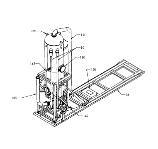
Figure 5 is a perspective view taken from the top and one side of the vessel
in a vertical lowest
position.
Figure 6 is a perspective view taken from the top and the other side of the
vessel in a vertical
position.
Figure 7 is a perspective view similar to Figure 5 but in a second raised
vertical position.
Figure 8 is a perspective view similar to Figure 6 but in a second vertical
position.
Figure 9 is a perspective view similar to Figure 7 but rotated 90 degrees
which illustrates the
demister.
Figure 10 is a perspective view taken from above and to one side of the skid
assembly.
Detailed Description of the Invention
A detailed description of one or more embodiments of the invention is provided
below along with
accompanying figures that illustrate the principles of the invention. Like
parts are given the
same number throughout the figures.
20537238.1
3
CA 2953605 2017-12-05

CA 02953605 2017-01-04
Figures 1 to 4 generally illustrate the pressure vessel 10 in the horizontal
position.
In particular the pressure vessel 10 includes a frame 12 for carrying the
vessel 10 and a
displaceable means or structure 14 for displacing the frame 12 carrying the
vessel 10 between
the horizontal position shown in Figures 1 to 4 and the vertical positions
shown in Figures 5 to 8
(to be described herein).
The pressure vessel 10 shows that the frame 12 is mounted on a skid 16 to
transport the vessel
from one place to another
As shown in one embodiment of the invention the displaceable means 14 can
comprise
hydraulic cylinder means 18. In particular the hydraulic cylinder means 18 can
comprise of at
10 least one hydraulic cylinder; or as shown hydraulic cylinders 18a and
18b mounted on either
side of the frame 12.
One end 20 of the hydraulic cylinders 18a and 18b is connected to the frame 12
and another
end 22 of the hydraulic cylinders 18a and 18b is connected to the skid 16 for:
(a) displacing the frame 12 carrying the vessel 10 between the horizontal
position as
shown in Figures 1 to 4 to the vertical position as shown in Figures 5 to 8;
and
(b) displacing the frame 12 carrying the vessel 10 in the vertical position as
shown in
Figures 5 to 8 between the first vertical position and a second vertical
position to be
described herein.
The frame 12 is pivotally connected at 23 to the skid 16 as shown. The skid 16
has spaced
longitudinal skid members 16a and 16b extending longitudinally so as to
connect at each end
24 and 26 to spaced end skid members 28 and 30 respectively.
The frame 12 has:
(a) generally spaced corner frame members 12a, 12b, 12c and 12d, connected to
first
end members 12e and second end members 12f, to define
(b) a generally rectangular cross section for receiving one end 10a of the
vessel 10 as
shown.
20537238 1
4

CA 02953605 2017-01-04
The one end 20 of the hydraulic cylinder 18 is connected to one of the first
end members 12e of
the frame 12. One of the second end members 12f of the frame 12 is pivotally
connected at 23
to the spaced longitudinal skid members 16a and 16b intermediate the end skid
members 28
and 30.
The other end 22 of the hydraulic cylinder 18a and 18b is:
(a) connected at the spaced longitudinal skid members 16a and 16b at a first
intermediate position 40 between the end skid members 28 and 30 for displacing
the
vessel from the horizontal position as shown in Figures 1 to 4 to the vertical
positions as
shown in Figures 5 to 8; and
(b) connected at said spaced longitudinal skid members 16a and 16b at a second
intermediate position 50 as shown in Figures 7 to 8, between the end skid
members 28
and 30 for displacing the vessel 10 in the vertical position shown in Figures
5 to 8
between a first vertical position as shown in Figures 5 and 6 and a second
vertical
position as shown in Figures 7 and 8.
In one embodiment the generally spaced corner frame members 12a, 12b, 12c, 12d
comprise a
telescoping means 60. More particularly the telescoping means 60 in one
embodiment can
comprise of each of the corner frame members 12a, 12b, 12c, 12d comprising an
inner corner
frame member 13a, 13b, 13c and 13d sliding within an outer corner frame member
15a, 15b,
15c and 15d and include detent means 70 for locking the frame 12 and the
vessel 10 at a
plurality of selected vertical positions between the first vertical position
shown in Figures 5 and 6
and a second vertical position shown in Figures 7 and 8. The detent means 70
can comprise in
one embodiment of a plurality of holes 72 presented by the inner corner frame
members 13a,
13b, 13c and 13d alignable with a hole 73b presented by the outer corner frame
members 15a,
15b, 15c, and 15d respectively, the telescoping members of at least one of a
side frame
member 12 and are adapted to receive a pin 80.
The vessel 10 further includes an inlet 90 and an outlet 100 and at least one
baffle 110
disposed in the vessel 10 at an angle relative to the horizontal or vertical
positions between the
inlet and outlet for separating sand or other solids from fluids such as
hydraulic fluids in the oil
and gas industry when the vessel is in the horizontal or vertical position.
20537238 1
5

The pressure vessel as described is useful in that the pressure vessel 10 can
easily be
transported from one location to another and depending on the orientation of
the well head the
pressure vessel can be operated in the horizontal position or in the vertical
position. Again
depending on the orientation of the well head the pressure vessel in the
vertical position can be
adjusted in height relative to the ground level so as to easily connect to the
equipment at the
well head.
Furthermore the pressure vessel as shown has an inlet diffuser 119 so as to
assist in the
diffusion of the sand mixed with the hydraulic fluid liquid as it enters the
inner chamber of the
vessel 10.
Moreover the embodiment as shown in the Figures illustrate the use of two
baffle plates 110
oriented at an angle relative to one another. In one embodiment the baffle
plates are disposed
at a 60 degree angle relative to the longitudinal axis of the vessel 10. The
baffles 200 have a
plurality of slots so as to assist in the separation of sand from the
hydraulic fluid.
The vessel 10 includes a plurality of lugs 120 so as to assist in tethering
the vessel 10 once in
its final position.
Furthermore the lugs 120 can be used to stabilize the vessel 10 in the
vertical position so as to
permit the other end 22 of the hydraulic cylinder 18 to be disconnected from
the spaced
longitudinal skid members 16a and 16b at the first intermediate position 40 so
as to connect the
second end 22 of the hydraulic cylinder 14 to the second intermediate position
50 of the skid
members 16a and 16b. Alternatively two hydraulic cylinders could be used
whereby one end 20
of each of the two hydraulic cylinders would be connected to the frame while
the other end 22 of
the two hydraulic cylinders would be connected to two different positions
namely positions 40
and 50 as described herein.
The vessel 10 includes an angled web 140 connected to the horizontal members
16a and 16b
between the two positions 40 and 50 so as to rigidify and strengthen the skid
16 as well as
provide a sliding angled surface 142 for the other end 22 of the hydraulic
cylinders 18a and 18b
to slide along when moving from the first intermediate position 40 to the
second intermediate
position 50 as shown.
The vessel 10 also includes a hydraulic fluid reservoir 150 so as to provide a
self-contained unit.
The pressure vessel 10 also includes a magnetic level gage 161.
20537238.2
6
CA 2953605 2018-04-04

The invention as described herein relates also to a method of operating a
vessel 10 in a
horizontal or vertical position comprising:
(a) placing one end 10a of the vessel 10 in a frame 12 mounted on a skid 16 in
a
horizontal position wherein the vessel 10 has an inlet 90 and an outlet 100
and at least
one baffle 110 disposed in the vessel 10 at an angle relative to the
horizontal position,
said baffle 110 disposed between the inlet 90 and outlet 100;
(b) selecting to operate the vessel 10 in a vertical position by moving the
frame 12 and
vessel 10 relative the skid 16 from the horizontal position to the vertical
position by
hydraulic cylinders 18 connected to the skid 16 and frame 12 between the inlet
90 and
outlet 100.
The frame 12 and vessel 10 are both pivotally moved at 23 relative to the skid
16 from the
horizontal to the vertical positions. The frame 12 and vessel 10 are
selectively moved in the
vertical position by the hydraulic cylinders 18a and 18b between a first
vertical position as
shown in Figures 5 and 6 and a second vertical position as shown in Figures 7
and 8.
The method also includes a step of connecting one end 20 of the hydraulic
cylinder 18 to the
frame 12 and connecting another end 22 of the hydraulic cylinder 18 to:
(a) a first position on the skid 16 for moving the vessel from the horizontal
to vertical
position; and
(b) a second position on the skid 16 for displacing the vessel 10 in the
vertical position
between a first vertical position and a second vertical position.
Figure 5 illustrates an inlet 90 gas out 121, and liquid out 125 as well as a
manway 160 for the
horizontal position. An inspection port 162 is also provided.
Figure 6 further shows inlet 90 and a sparge 164.
In general, in the following claims, the terms used should not be construed to
limit the invention
to the specific embodiments disclosed in the specification and the claims, but
should be
construed to include all possible embodiments along with the full scope of
embodiments to
which such claims are entitled. Accordingly the invention is not limited by
the disclosure, but
instead its scope is to be determined by the following claims.
20537238.1
7
CA 2953605 2017-12-05

Representative Drawing
A single figure which represents the drawing illustrating the invention.
Administrative Status

For a clearer understanding of the status of the application/patent presented on this page, the site Disclaimer , as well as the definitions for Patent , Administrative Status , Maintenance Fee  and Payment History  should be consulted.

Administrative Status

Title Date
Forecasted Issue Date 2019-10-22
(22) Filed 2017-01-04
Examination Requested 2017-01-04
(41) Open to Public Inspection 2017-03-29
(45) Issued 2019-10-22

Abandonment History

There is no abandonment history.

Maintenance Fee

Last Payment of $210.51 was received on 2023-12-29


 Upcoming maintenance fee amounts

Description Date Amount
Next Payment if small entity fee 2025-01-06 $100.00
Next Payment if standard fee 2025-01-06 $277.00

Note : If the full payment has not been received on or before the date indicated, a further fee may be required which may be one of the following

  • the reinstatement fee;
  • the late payment fee; or
  • additional fee to reverse deemed expiry.

Patent fees are adjusted on the 1st of January every year. The amounts above are the current amounts if received by December 31 of the current year.
Please refer to the CIPO Patent Fees web page to see all current fee amounts.

Payment History

Fee Type Anniversary Year Due Date Amount Paid Paid Date
Advance an application for a patent out of its routine order $500.00 2017-01-04
Request for Examination $800.00 2017-01-04
Registration of a document - section 124 $100.00 2017-01-04
Application Fee $400.00 2017-01-04
Registration of a document - section 124 $100.00 2017-12-05
Registration of a document - section 124 $100.00 2018-04-04
Maintenance Fee - Application - New Act 2 2019-01-04 $100.00 2018-12-19
Final Fee $300.00 2019-09-12
Maintenance Fee - Patent - New Act 3 2020-01-06 $100.00 2020-01-06
Maintenance Fee - Patent - New Act 4 2021-01-04 $100.00 2020-12-28
Registration of a document - section 124 2021-02-26 $100.00 2021-02-26
Maintenance Fee - Patent - New Act 5 2022-01-04 $203.59 2022-01-03
Maintenance Fee - Patent - New Act 6 2023-01-04 $203.59 2022-12-30
Maintenance Fee - Patent - New Act 7 2024-01-04 $210.51 2023-12-29
Owners on Record

Note: Records showing the ownership history in alphabetical order.

Current Owners on Record
ENERCORP ENGINEERED SOLUTIONS INC.
Past Owners on Record
DYNACORP FABRICATORS INC.
ENERCORP SAND SOLUTIONS INC.
Past Owners that do not appear in the "Owners on Record" listing will appear in other documentation within the application.
Documents

To view selected files, please enter reCAPTCHA code :


To view images, click a link in the Document Description column. To download the documents, select one or more checkboxes in the first column and then click the "Download Selected in PDF format (Zip Archive)" or the "Download Selected as Single PDF" button.

List of published and non-published patent-specific documents on the CPD .

If you have any difficulty accessing content, you can call the Client Service Centre at 1-866-997-1936 or send them an e-mail at CIPO Client Service Centre.


Document
Description 
Date
(yyyy-mm-dd) 
Number of pages   Size of Image (KB) 
Maintenance Fee Payment 2020-01-06 1 33
Abstract 2017-01-04 1 13
Description 2017-01-04 7 323
Claims 2017-01-04 4 129
Drawings 2017-01-04 5 157
Cover Page 2017-02-17 2 50
Amendment 2017-07-31 11 313
Claims 2017-07-31 4 112
Examiner Requisition 2017-08-08 3 180
Amendment 2017-08-30 10 287
Claims 2017-08-30 3 108
Examiner Requisition 2017-09-11 3 187
Amendment 2017-12-05 23 734
Modification to the Applicant/Inventor / Response to section 37 2017-12-05 10 272
Claims 2017-12-05 7 222
Drawings 2017-12-05 5 154
Description 2017-12-05 7 291
Examiner Requisition 2018-01-04 3 163
Amendment 2018-04-04 20 651
Claims 2018-04-04 8 247
Description 2018-04-04 7 297
Drawings 2018-04-04 5 152
Examiner Requisition 2018-04-17 3 175
Amendment 2018-07-17 19 540
Claims 2018-07-17 8 250
Examiner Requisition 2018-08-03 3 196
Amendment 2018-11-02 21 542
Examiner Requisition 2018-11-13 3 212
Claims 2018-11-02 8 237
Maintenance Fee Payment 2018-12-19 1 26
Amendment 2019-02-13 22 676
Claims 2019-02-13 6 201
Final Fee 2019-09-12 1 30
Representative Drawing 2019-10-03 1 14
Cover Page 2019-10-03 1 44
Prosecution-Amendment 2017-02-01 1 22
Assignment 2017-01-04 5 155
Prosecution-Amendment 2017-01-04 2 59
PPH Request 2017-03-29 1 42
Representative Drawing 2017-03-30 1 23
Examiner Requisition 2017-05-01 3 178