Note: Descriptions are shown in the official language in which they were submitted.
CA 02954070 2016-12-30
WO 2016/007661 PCT/US2015/039596
CAST BUMPER ASSEMBLY AND METHOD
OF MANUFACTURING SAME
CROSS REFERENCE TO RELATED APPLICATIONS
[0001] This PCT Patent Application claims the benefit of and priority to
U.S.
Provisional Patent Application Serial No. 62/022,366 filed July 9, 2014, the
entire
disclosure of the application being considered part of the disclosure of this
application, and
hereby incorporated by reference.
BACKGROUND OF THE INVENTION
1. Field of the Invention
[0002] The subject invention is related to a vehicle bumper assembly
including a
bumper beam and a crash box. The subject invention is also related to a method
of
manufacturing the bumper assembly.
2. Description of the Prior Art
[0003] Vehicle bumper assemblies are known for providing energy absorbing
characteristics. Body structures of a vehicle are provided with so-called
crash boxes. Such
crash boxes are disposed on the end of a frame member of a vehicle body
structure so as to
absorb an impact load of certain predetermined value, thereby eliminating
deformation of
the frame member of the vehicle body.
[0004] Bumper assemblies include a bumper beam typically extending
laterally
across the front or rear of a vehicle and provided generally for absorbing
energy during a
frontal or rear impact. Such bumper beams are disposed under a cosmetic or
fascia bumper
and are mounted to a vehicle frame with use of the so-called crash boxes
referred to above.
The crash-boxes are designed to fold upon such frontal or rear impacts.
[0005] The crash boxes are mounted to the vehicle frame and the bumper
beam by
many different means including, without limitation, welding, adhesives,
fasteners, etc.
1
CA 02954070 2016-12-30
WO 2016/007661 PCT/US2015/039596
Such crash boxes and bumper beams can be made of many different types of
materials
including, without limitation, steel, aluminum, and/or magnesium. In addition,
such crash
boxes and bumper beams are manufactured by way of extrusion, steel roll
forming, or hot
stamping manufacturing processes.
[0006] There remains a significant and continuing need for a design of a
crash box
and bumper beam that allows for lower manufacturing and assembling costs along
with
improved energy absorption properties. There also remains a significant and
continuing
need for an improved method of manufacturing a vehicle bumper assembly which
is cost
effective, reduces manufacturing steps, and also able to produce an assembled
product
having improved energy absorption and other performance properties.
SUMMARY OF THE INVENTION
[0007] The subject invention includes a vehicle bumper assembly wherein
at least
one of the bumper beam or the crash box is a metal cast component. The subject
invention
also includes a method of manufacturing a vehicle bumper assembly which
includes metal
casting at least one of the bumper beam or the crash box.
[0008] A bumper assembly according to the subject invention is
advantageous
because the cast components can be designed and manufactured with a specific
geometry
that can be tuned to meet weight, price, and performance requirements for the
bumper
assembly, all with a casting manufacturing process that reduces process steps
and costs. In
addition, the cast components of the subject bumper assembly are lighter than
equivalent
components prior art bumper assemblies manufactured by way of extrusion, steel
roll
forming, or hot stamping manufacturing processes, and thus leads to
performance
improvements.
2
CA 02954070 2016-12-30
WO 2016/007661 PCT/US2015/039596
BRIEF DESCRIPTION OF THE DRAWINGS
[0009] Other advantages of the present invention will be readily
appreciated, as the
same becomes better understood by reference to the following detailed
description when
considered in connection with the accompanying drawings wherein:
[0010] Figure 1 is a perspective view of a cast bumper beam;
[0011] Figure 2 is a top view of the cast bumper beam illustrating a
plurality of
reinforcement ribs integrally cast therewith;
[0012] Figure 3 is a perspective view of a first embodiment of the bumper
assembly
illustrating the cast bumper beam secured to a crash box;
[0013] Figure 4 is a perspective view of a second embodiment of the
bumper
assembly illustrating a cast crash box secured to a bumper beam;
[0014] Figure 5 is a perspective view of a third embodiment of the bumper
assembly
illustrating a cast bumper beam integral with a cast crash box;
[0015] Figure 6 is a top view of the third embodiment of the bumper
assembly
illustrating a plurality of reinforcement ribs integrally cast with the cast
bumper beam;
[0016] Figure 7A is a perspective view of a fourth embodiment of the
bumper
assembly including a W-shaped cast bumper beam integral with a cast crash box;
[0017] Figure 7B is a top view of the fourth embodiment of the bumper
assembly;
[0018] Figure 7C is a front view of the fourth embodiment of the bumper
assembly;
[0019] Figure 7D is a cross-sectional view taken along A-A of Figure 7A;
[0020] Figure 8A is a perspective view of a fifth embodiment of the
bumper
assembly including an H-shaped cast bumper beam integral with a cast crash box
and each
of the cast bumper beam and cast crash box having open top and bottom
surfaces;
[0021] Figure 8B is a top view of the fifth embodiment of the bumper
assembly;
[0022] Figure 8C is a front view of the fifth embodiment of the bumper
assembly;
3
CA 02954070 2016-12-30
WO 2016/007661 PCT/US2015/039596
[0023] Figure 8D is a cross-sectional view along B-B of Figure 8A;
[0024] Figure 8E is a partial perspective view of the fifth embodiment of
the
bumper assembly;
[0025] Figure 9A is a perspective view of a sixth embodiment of the
bumper
assembly including an H-shaped cast bumper beam integral with a cast crash box
having
closed top and bottom surfaces;
[0026] Figure 9B is a top view of the sixth embodiment of the bumper
assembly;
[0027] Figure 9C is a front view of the sixth embodiment of the bumper
assembly;
[0028] Figure 9D is a cross-sectional view along C-C of Figure 8A;
[0029] Figure 9E is a partial perspective view of the sixth embodiment of
the
bumper assembly;
[0030] Figure 10A is a top view of the bumper assembly shown in Figure 8A
illustrating a plurality of weight reduction holes defined by the H-shaped
cast bumper beam
and the cast crash box; and
[0031] Figure 10B is a top view of the bumper assembly shown in Figure 9A
illustrating a plurality of weight reduction holes defined by the H-shaped
cast bumper beam.
DETAILED DESCRIPTION OF THE ENABLING EMBODIMENTS
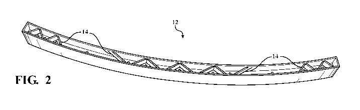
[0032] Referring to the Figures, wherein like numerals indicate
corresponding parts
throughout the several views, Figure 1 is a perspective view of a cast bumper
beam, shown
generally at 12, for use in a vehicle bumper assembly. Such vehicle bumper
assemblies are
known for providing energy absorbing characteristics, and the cast bumper beam
12
typically extends laterally across the front or rear of a vehicle (not shown)
and is mounted to
a vehicle frame with use of the crash boxes. The cast bumper beam 12 is cast
from metal
materials, such as aluminum or magnesium, and has a specific design of
geometry that can
be tuned to meet the energy absorbance and weight requirements for the overall
bumper
4
CA 02954070 2016-12-30
WO 2016/007661 PCT/US2015/039596
assembly (not expressly shown). However, other types of metal and/or metal
alloys may be
selected without departing from the scope of the subject disclosure. Although
not expressly
shown, the cast bumper beam 12 can have variable, non-constant sections with
regard to
width, geometry, and/or thickness.
[0033] As best shown in Figure 2, the cast bumper beam 12 can include a
plurality
of reinforcing ribs 14 having a "V" shape that are each cast integrally with
the bumper beam
12 and arranged to facilitate controlled crash properties for the overall
bumper assembly
(not expressly shown). It should be appreciated that the "V"-shaped
reinforcing ribs 14
could also be any number of other shapes depending on the design criteria
selected
including, without limitation, the amount of structural support desired,
weight, and/or the
amount of desired crush. As best shown in Figure 3, the cast bumper beam 12
can be
mounted to or combined with a crash box 16 that is manufactured according to
traditional
manufacturing processes, such as extrusion, steel roll forming, hot stamping,
or the like, to
form a first embodiment of the bumper assembly, generally shown at 10. In a
preferred
arrangement, the cast bumper beam 12 is welded to the crash box 16, however
many other
different means, including, without limitation, adhesives, fasteners, or the
like, can also be
used without departing from the scope of the subject disclosure.
[0034] Figure 4 illustrates a second embodiment of the bumper assembly,
shown
generally at 20, in which a cast crash box 26 is be mounted to or combined
with a bumper
beam 22 manufactured according to traditional manufacturing processes, such as
extrusion,
steel roll forming, hot stamping, or the like. The cast crash box 26 is cast
from metal
materials, such as aluminum or magnesium, and has a specific design of
geometry that can
be tuned to meet the energy absorbance and weight requirements for the overall
bumper
assembly 20. However, other types of metal and/or metal alloys may be selected
without
departing from the scope of the subject disclosure. Similar to the first
embodiment, the cast
CA 02954070 2016-12-30
WO 2016/007661 PCT/US2015/039596
crash box 26 can be welded to the bumper beam 22, however many other different
means,
including, without limitation, adhesives, fasteners, or the like, can also be
used without
departing from the scope of the subject disclosure.
[0035] Figure 5 illustrates a third embodiment of the bumper assembly,
shown
generally at 30, which includes a cast bumper beam 32 integral with a cast
crash box 36.
Put another way, in the third embodiment of the bumper assembly 30, the cast
bumper beam
32 and the cast crash box 36 are manufacturing integral with one another
during the same
casting process. Each of the cast bumper beam 32 and the cast crash box 36 are
cast from
metal materials, such as aluminum or magnesium, however, other types of metal
and/or
metal alloys may be selected without departing from the scope of the subject
disclosure.
Each of the cast bumper beam 32 and cast crash box 36 have a specific design
of geometry
that can be tuned to meet the energy absorbance and weight requirements for
the overall
bumper assembly 30, with one or both of these components having variable, non-
constant
sections with regard to width, geometry, and/or thickness.
[0036] Unlike the first and second embodiments of the bumper assembly 10,
20, the
third embodiment of the bumper assembly advantageously does not require a
weld,
adhesive, or other fastener to effectuate securement of the cast crash box 36
to the cast
bumper beam 32. Accordingly, the third embodiment of the bumper assembly 30
reduces
manufacturing steps and costs, and results in a bumper assembly that is
stronger, cheaper,
and lighter over prior art designs. In an exemplary embodiment, the bumper
assembly 30
can be approximately 0.5 kg lighter than prior art bumper assembly designs.
[0037] As best shown in Figure 5, the cast crash box 36 can also include
a mounting
plate 38 cast integral therewith for use in mounting the bumper assembly 30 to
a vehicle
frame (not expressly shown). As best shown in Figure 6, the cast bumper beam
32 can also
include a plurality of reinforcing ribs 34 having a "V" shape that are each
cast integrally
6
CA 02954070 2016-12-30
WO 2016/007661 PCT/US2015/039596
with the cast bumper beam 32 and arranged to facilitate controlled crash
properties for the
overall bumper assembly (not expressly shown). It should be appreciated that
the "V"-
shaped reinforcing ribs 34 could also be any number of other shapes depending
on the
design criteria selected including, without limitation, the amount of
structural support
desired, weight, and/or the amount of desired crush.
[0038] Figures 7A-7D illustrate a fourth embodiment of the bumper
assembly,
shown generally at 40, which includes a cast bumper beam 42 integral with a
cast crash box
46. Similar to the third embodiment, the cast bumper beam 42 and the cast
crash box 46 of
the fourth embodiment of the bumper assembly 40 are also manufactured integral
with one
another during the same casting process. Each of the cast bumper beam 42 and
the cast
crash box 46 are cast from metal materials, such as aluminum or magnesium,
however,
other types of metal and/or metal alloys may be selected without departing
from the scope
of the subject disclosure. Each of the cast bumper beam 42 and cast crash box
46 have a
specific design of geometry that can be tuned to meet the energy absorbance
and weight
requirements for the overall bumper assembly 40, with one or both of these
components
having variable, non-constant sections with regard to width, geometry, and/or
thickness.
The fourth embodiment of the bumper assembly also advantageously does not
require a
weld, adhesive, or other fastener to effectuate securement of the cast crash
box 46 to the
cast bumper beam 42. Accordingly, the fourth embodiment of the bumper assembly
30
reduces manufacturing steps and costs, and results in a bumper assembly that
is stronger,
cheaper, and lighter over prior art designs.
[0039] As best shown in Figure 7A, each of the cast crash boxes 46 define
an
internal cavity 47 and the cast bumper beam 42 defines a plurality of front
openings 44 each
disposed adjacent to and in communication with a respective internal cavity 47
of the cast
crash boxes 46. The incorporation of the front openings 44 into the cast
bumper beam 42
7
CA 02954070 2016-12-30
WO 2016/007661 PCT/US2015/039596
improves the manufacturability of the cast bumper assembly 40. As best shown
in Figure
7D, the cast bumper beam can also be cast to have a "W" shape extending along
at least a
portion of its length to facilitate controlled crash properties for the bumper
assembly 40.
[0040] Figures 8A-8E illustrate a fifth embodiment of the bumper
assembly, shown
generally at 50, which includes a cast bumper beam 52 integral with a cast
crash box 56.
Put another way, similar to the third and fourth embodiments, the cast bumper
beam 52 and
the cast crash box 56 of the fifth embodiment of the bumper assembly 50 are
also
manufactured integral with one another during the same casting process. Each
of the cast
bumper beam 52 and the cast crash box 56 are cast from metal materials, such
as aluminum
or magnesium, however, other types of metal and/or metal alloys may be
selected without
departing from the scope of the subject disclosure. Each of the cast bumper
beam 52 and
the cast crash box 56 have a specific design of geometry that can be tuned to
meet the
energy absorbance and weight requirements for the overall bumper assembly 50,
with one
or both of these components having variable, non-constant sections with regard
to width,
geometry, and/or thickness. The fifth embodiment of the bumper assembly 50
also
advantageously does not require a weld, adhesive, or other fastener to
effectuate securement
of the cast crash box 56 to the cast bumper beam 52. Accordingly, the fifth
embodiment of
the bumper assembly 50 reduces manufacturing steps and costs, and results in a
bumper
assembly that is stronger, cheaper, and lighter over prior art designs.
[0041] As best shown in Figure 8A and 8D-8E, each of the cast bumper beam
52
and cast crash boxes 56 are open along a top and bottom portion to improve the
manufacturability of the cast bumper assembly 50. As best shown in Figures 8A-
8B and
8E, the cast bumper beam 52 can include a plurality of reinforcing ribs 54
having a "V"
shape that are each cast integrally with the bumper beam 52 and the cast crash
boxes 56 can
include a plurality of reinforcing ribs 58 having an "X" shape that are each
cast integrally
8
CA 02954070 2016-12-30
WO 2016/007661 PCT/US2015/039596
with the crash box 56. The reinforcing ribs 54, 58 are arranged to facilitate
controlled crash
properties for the bumper assembly 50. It should be appreciated that the "V"-
shaped and
"X"-shaped reinforcing ribs 54, 58 could also be any number of other shapes
depending on
the design criteria selected including, without limitation, the amount of
structural support
desired, weight, and/or the amount of desired crush. As best shown in Figures
8D and 8E,
the cast bumper beam 52 can also be cast to have an "H" shape and define an
additional
horizontal or transverse rib 59 extending along at least a portion of the
length to further
control the crash properties of the bumper assembly 50.
[0042] Figures 9A-9E illustrate a sixth embodiment of the bumper
assembly, shown
generally at 60, which includes a cast bumper beam 62 integral with a cast
crash box 66.
Similar to the third, fourth, and fifth embodiments, the cast bumper beam 62
and the cast
crash box 66 of the sixth embodiment of the bumper assembly 60 are
manufactured integral
with one another during the same casting process. Each of the cast bumper beam
62 and the
cast crash box 66 are cast from metal materials, such as aluminum or
magnesium, however,
other types of metal and/or metal alloys may be selected without departing
from the scope
of the subject disclosure. Each of the cast bumper beam 62 and cast crash box
66 have a
specific design of geometry that can be tuned to meet the energy absorbance
and weight
requirements for the overall bumper assembly 60, with one or both of these
components
having variable, non-constant sections with regard to width, geometry, and/or
thickness.
The sixth embodiment of the bumper assembly 60 also advantageously does not
require a
weld, adhesive, or other fastener to effectuate securement or mounting of the
cast crash box
66 to the cast bumper beam 62. Accordingly, the sixth embodiment of the bumper
assembly 60 reduces manufacturing steps and costs, and results in a bumper
assembly that
is stronger, cheaper, and lighter over prior art designs.
9
CA 02954070 2016-12-30
WO 2016/007661 PCT/US2015/039596
[0043] As best shown in Figure 9A-9B and 9E, the cast bumper beam 62 is
open
along a top and bottom portion of the bumper assembly 60, while the cast crash
box 66 is
closed along these same portions. As best shown in Figures 9A-9B and 9E, the
cast bumper
beam 62 can include a plurality of reinforcing ribs 64 having a "V" shape that
are each cast
integrally with the cast bumper beam 62. However, it should be appreciated
that the "V"-
shaped reinforcing ribs 64 could also be any number of other shapes depending
on the
design criteria selected including, without limitation, the amount of
structural support
desired, weight, and/or the amount of desired crush. As best shown in Figures
9D and 9E,
similar to the fifth embodiment, the cast bumper beam 62 can also be cast to
have an "H"
shape and define an additional horizontal or transverse rib 69 extending along
at least a
portion of the length to further control the crash properties of the bumper
assembly 60.
[0044] Figures 10A and 10B illustrate an alternative arrangement of the
fifth and
sixth embodiments of the bumper assembly 50, 60, respectively, in which the
horizontal or
transverse rib 59, 69 of the bumper beam 52, 62 defines a plurality of weight
reduction
holes 70 to further reduce the overall weight of the cast bumper assembly 50,
60. As
shown in Figure 10A, in the alternative arrangement of the fifth embodiment of
the bumper
assembly, the cast crash box 56 can also define a plurality of weight
reduction holes to even
further reduce the overall weight of the cast bumper assembly 50.
[0045] Although not expressly shown in the Figures, one or both of the
bumper
beam or the crash box in any of the aforementioned embodiments of the bumper
assembly
can also be cast to incorporate various design features including but not
limited to: head
lamps, ambient air sensors, pedestrian brackets, collision avoidance sensors,
a hood latch,
pedestrian protection systems, horns, grilles, fog lamps, toe hooks, threaded
inserts, and
neoprene shock absorption materials. As such, the cast bumper assembly can
incorporate
design features and shapes that would otherwise have to be welded onto prior
art bumper
CA 02954070 2016-12-30
WO 2016/007661 PCT/US2015/039596
assemblies, or stretch bent into prior art bumper assemblies. Thus, the cast
bumper
assembly avoids the machining and welding operations that are required to
incorporate
these features into prior art bumper assemblies manufactured by way of
extrusion, steel roll
forming, hot stamping, or the like.
[0046] Although not expressly shown in the figures, the cast bumper beam
in any of
the aforementioned embodiments of the bumper assembly can also be cast to have
a "U"-
shape or "C"-shape extending along a portion of its length.
[0047] Although not expressly shown in the Figures, one or both of the
bumper
beam or the crash box in any of the aforementioned embodiments of the bumper
assembly
can also include absorption inserts placed anywhere within or along the bumper
assembly.
[0048] The foregoing invention has been described in accordance with the
relevant
legal standards, thus the description is exemplary rather than limiting in
nature. Variations
and modifications to the disclosed embodiment may become apparent to those
skilled in the
art and fall within the scope of the invention.
11