Note: Descriptions are shown in the official language in which they were submitted.
CA 02954155 2017-01-03
Docket No. PJFA-16551-POT
1
DESCRIPTION
ULTRASONIC FLAW DETECTION APPARATUS AND ULTRASONIC FLAW
DETECTION METHOD
Field
[0001] The present invention relates to an ultrasonic
flaw detection apparatus and an ultrasonic flaw detection
method, for performing ultrasonic flaw detection on a
welded seam portion of an electric resistance welded pipe.
Background
[0002] Electric resistance welded pipes are generally
manufactured by a process of forming a steel plate into a
pipe shape and connecting both width direction end portions
of the steel plate by welding while pressing the width
direction end portions against each other. In order to
obtain high welding quality in such a process of
manufacturing electric resistance welded pipes, an electric
resistance welded pipe is made into a product by:
ultrasonic flaw detection on a welded seam portion by use
of an ultrasonic flaw detection apparatus and annealing (a
process of tempering the welded seam portion that has
approached a quenching state by welding) of the welded seam
portion with a seam annealer.
[0003] When ultrasonic flaw detection is performed on a
welded seam portion, normally, after weld beads are cut or
after a hydraulic test, angle beam testing, in which
ultrasonic wave signals are caused to be obliquely incident
on the welded seam portion, is performed. In angle beam
testing, ultrasonic flaw detection needs to be performed
with a sensor head being positioned with respect to the
welded seam portion such that the ultrasonic wave signals
are incident on the welded seam portion, the sensor head
including an ultrasonic probe. In particular, when focused
ultrasonic wave signals are used, since focal depth of the
CA 02954155 2017-01-03
Docket No. PJFA-16551-PCT
2
ultrasonic wave signals becomes short, positioning thereof
requires accuracy.
[0004] However, since electric resistance welded pipes
receive various forces on manufacturing lines, their welded
seam portions are not necessarily positioned on a central
line of the sensor head, and may be displaced in a pipe
circumference direction from the central line of the sensor
head. Thus, techniques have been proposed, the techniques
including: a seam position detection technique using
reflected ultrasonic wave signals from a defect in a welded
seam portion (see Patent Literature 1); and a technique for
detecting a seam position from a temperature distribution
obtained by imaging of a welded seam portion of an electric
resistance welded pipe with an infrared camera, and for
further correcting a seam position by use of reflected
ultrasonic wave signals from minute oxides, which are
present in the welded seam portion and do not influence the
quality (see Patent Literature 2).
Citation List
Patent Literature
[0005] Patent Literature 1: Japanese Patent Application
Laid-open No. 2011-227060
Patent Literature 2: Japanese Patent Application
Laid-open No. 2009-222408
Summary
Technical Problem
[0006] However, in both of the techniques described in
Patent Literature 1 and Patent Literature 2, the seam
positions are detected based on the reflected ultrasonic
wave signals from the minute oxides, which are present in
the welded seam portions and do not influence the quality,
the reflected ultrasonic wave signals being obtained by
electronic or mechanical scanning near the welded seam
3
portions of the electric resistance welded pipes with ultrasonic
wave signals in the pipe circumference direction. Therefore,
according to the techniques described in Patent Literature 1 and
Patent Literature 2, when the minute oxides are not present in
the welded seam portions, the seam positions are not detectable.
[0007] The present invention has been made in view of the
above described problem, and an object thereof is to provide an
ultrasonic flaw detection apparatus and an ultrasonic flaw
detection method, which enable a seam position to be accurately
detected and flaw detection on a welded seam portion to be
accurately performed, without reliance on reflected ultrasonic
wave signals from minute oxides present in the welded seam
portion.
Solution to Problem
[0008] An ultrasonic flaw detection apparatus, comprising: a
seam detection unit that captures a thermal image of a welded
seam portion of an electric resistance welded pipe; an
ultrasonic flaw detection sensor head that is installed
downstream in a pipe manufacturing direction from the seam
detection unit and includes an ultrasonic probe configured to
perform ultrasonic flaw detection on the welded seam portion; a
seam position calculation unit that calculates a seam position
and a bead cutting position of the electric resistance welded
pipe by using the thermal image of the welded seam portion
23 captured by the seam detection unit; a bead cutting band
detection unit that is installed immediately before or
immediately after an installation position of the ultrasonic
flaw detection sensor head and that detects a bead cutting band
of the electric resistance welded pipe; a bead cutting position
calculation unit that calculates, based on the bead cutting band
detected by the bead cutting band detection unit, a bead cutting
position of the electric resistance welded pipe; a tracking
CA 2954155 2019-04-01
4
movement amount calculation unit that calculates a tracking
movement amount of the ultrasonic flaw detection sensor head by
using the seam position and bead cutting position calculated by
the seam position calculation unit and the bead cutting position
calculated by the bead cutting position calculation unit; and a
sensor head driving unit that moves the ultrasonic flaw
detection sensor head to track the welded seam portion of the
electric resistance welded pipe according to the tracking
movement amount calculated by the tracking movement amount
calculation unit, wherein the bead cutting band detection unit
includes: a first light source that emits illumination light to
the vicinity of the welded seam portion from an upper left side
direction of the electric resistance welded pipe; a second light
source that emits illumination light to the vicinity of the
welded seam portion from an upper right side direction of the
electric resistance welded pipe; and an image detection unit
that detects images of the vicinity of the welded seam portion
when the illumination light is emitted from the first and second
light sources and that is interposed between the first light
source and the second light source, and the bead cutting
position calculation unit calculates a minimum luminance image
from the image detected when the illumination light is emitted
from the first light source and the image detected when the
illumination light is emitted from the second light source,
calculates a luminance distribution for evaluation, which is a
luminance distribution obtained as a result of calculating
maximum value of luminance in a predetermined evaluation range
in the pipe manufacturing direction with respect to a/the pipe
circumference direction of the minimum luminance image, and
based on the luminance distribution for evaluation and a
predetermined threshold, calculates the bead cutting position.
CA 2954155 2019-04-01
5
[0009] The ultrasonic flaw detection apparatus according to
the above-described invention, wherein the seam position
calculation unit calculates a temperature distribution in a pipe
circumference direction of the electric resistance welded pipe
from the thermal image captured by the seam detection unit, and
calculates, as the seam position, a middle point between pipe
circumference direction positions where temperature exceeds a
predetermined threshold.
[0010] The ultrasonic flaw detection apparatus according to
the above-described invention, wherein the bead cutting position
calculation unit calculates a chart obtained as a result of
calculating maximum luminance value in the pipe circumference
direction with respect to the pipe manufacturing direction of
the minimum luminance image, and sets a range in the pipe
manufacturing direction, in which the chart exceeds a
predetermined threshold, as the predetermined evaluation range.
[0011] The ultrasonic flaw detection apparatus according to
the above-described invention, wherein the bead cutting position
calculation unit calculates a reference luminance distribution,
which is a luminance distribution obtained as a result of
calculating a maximum value of luminance in the pipe
manufacturing direction with respect to the pipe circumference
direction in a reference luminance calculation range set in a
predetermined range of the minimum luminance image, and
calculates, based on a luminance distribution obtained as a
result of subtracting the reference luminance distribution from
the luminance distribution for evaluation, the bead cutting
position.
[0012] The ultrasonic flaw detection apparatus according to
the above-described invention, wherein an ultrasonic flaw
detection method being applied to the ultrasonic flaw detection
CA 2954155 2019-04-01
6
sensor head is an ultrasonic flaw detection method that uses
water as a sound coupling material.
[0013] An
ultrasonic flaw detection method, including: a seam
detection step of capturing a thermal image of a welded seam
portion of an electric resistance welded pipe upstream in a pipe
manufacturing direction of an installation position of an
ultrasonic flaw detection sensor head having an ultrasonic probe
for performing ultrasonic flaw detection on the welded seam
portion; a seam position calculation step of calculating a seam
position and a bead cutting position of the electric resistance
welded pipe by using the thermal image of the welded seam
portion captured in the seam detection step; a bead cutting band
detection step of detecting a bead cutting band of the electric
resistance welded pipe immediately before or immediately after
the installation position of the ultrasonic flaw detection
sensor head; a bead cutting position calculation step of
calculating, based on the bead cutting band detected in the bead
cutting band detection step, a bead cutting position of the
electric resistance welded pipe; a tracking movement amount
calculation step of calculating a tracking movement amount of
the ultrasonic flaw detection sensor head by using the seam
position and bead cutting position calculated in the seam
position calculation step and the bead cutting position
calculated in the bead cutting position calculation step; and a
sensor head driving step of moving the ultrasonic flaw detection
sensor head to track the welded seam portion of the electric
resistance welded pipe according to the tracking movement amount
calculated in the tracking movement amount calculation step,
wherein the bead cutting band detection step includes: a first
light emitting step of emitting illumination light to the
vicinity of the welded seam portion from an upper left side
direction of the electric resistance welded pipe; a second light
CA 2954155 2019-04-01
7
emitting step of emitting illumination light to the vicinity of
the welded seam portion from an upper right side direction of
the electric resistance welded pipe; and a detecting step of
detecting images of the vicinity of the welded seam portion when
the illumination light is emitted in the first and second light
emitting steps, and the bead cutting position calculation step
includes: calculating a minimum luminance image from the image
detected when the illumination light is emitted from the first
light source and the image detected when the illumination light
is emitted from the second light source; calculating a luminance
distribution for evaluation, which is a luminance distribution
obtained as a result of calculating maximum value of luminance
in a predetermined evaluation range in the pipe manufacturing
direction with respect to a/the pipe circumference direction of
the minimum luminance image; and calculating the bead cutting
position based on the luminance distribution for evaluation and
a predetermined threshold.
Advantageous Effects of Invention
[0015] By the ultrasonic flaw detection apparatus and the
ultrasonic flaw detection method according to the present
invention, without reliance on reflected waves from minute
oxides present in a welded seam portion, a seam position is able
to be detected accurately, and flaw detection on the welded seam
portion is able to be performed accurately.
Brief Description of Drawings
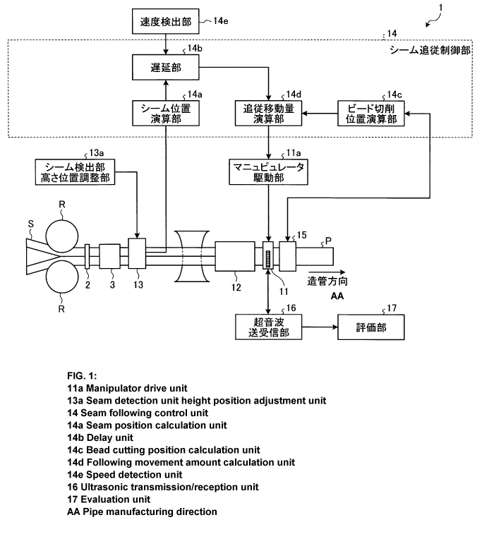
[0016] FIG. 1 is a schematic diagram illustrating an overall
configuration of an ultrasonic flaw detection apparatus
according to an embodiment of the present invention.
FIG. 2 is a schematic diagram illustrating a configuration
of a bead cutting band detection unit illustrated in FIG. 1.
CA 2954155 2019-04-01
7a
FIG. 3 is a flow chart illustrating a flow of a seam
tracking control process according to the embodiment of the
present invention.
FIG. 4 is a diagram illustrating an example of a thermal
image of a welded seam, portion of an electric resistance welded
pipe, the thermal image acquired by a seam detection unit.
FIG. 5 is a diagram illustrating an example of a
temperature distribution of the electric resistance welded pipe
in a pipe circumference direction.
FIG. 6 is a diagram illustrating a method of calculating a
seam position of the electric resistance welded pipe.
FIG. 7 is a diagram illustrating a method of
CA 2954155 2019-04-01
CA 02954155 2017-01-03
Docket No. PJFA-16551-PCT
8
calculating a bead cutting position from the temperature
distribution of the electric resistance welded pipe in the
pipe circumference direction.
FIG. 8 is a diagram illustrating the method of
calculating a bead cutting position from the temperature
distribution of the electric resistance welded pipe in the
pipe circumference direction.
FIG. 9 is a diagram illustrating an example of an
image of a bead cutting band captured by irradiation with
illumination light from one of light sources.
FIG. 10 is a diagram illustrating an example of an
image of the bead cutting band captured by irradiation with
illumination light from the other light source.
FIG. 11 is a diagram illustrating a method of
extracting the bead cutting band by a minimum luminance
calculation process.
FIG. 12 is a flow chart illustrating a flow of a bead
cutting position calculation process according to the
embodiment of the present invention.
FIG. 13 is a diagram illustrating processing of Steps
S14 to S19 illustrated in FIG. 12.
FIG. 14 is a diagram illustrating processing of Step
S20 illustrated in FIG. 12.
Description of Embodiments
[0017] Hereinafter, with reference to the drawings, a
configuration and operation of an ultrasonic flaw detection
apparatus according to an embodiment of the present
invention will be described.
[0018] [Configuration]
First, with reference to FIG. 1 and FIG. 2, the
configuration of the ultrasonic flaw detection apparatus
according to the embodiment of the present invention will
be described.
CA 02954155 2017-01-03
Docket No. PJFA-16551-PCT
9
[ 0 0 19 ] FIG. 1 is a schematic diagram illustrating an
overall configuration of the ultrasonic flaw detection
apparatus according to the embodiment of the present
invention. FIG. 2 is a schematic diagram illustrating a
configuration of a bead cutting band detection unit
illustrated in FIG. 1.
[0020] As illustrated in FIG. 1, an ultrasonic flaw
detection apparatus 1 according to the embodiment of the
present invention is an apparatus that performs ultrasonic
flaw detection on a welded seam portion of an electric
resistance welded pipe P, which is manufactured by: both
width direction end portions of a steel plate S being
connected to each other by welding by a welding machine 2,
the steel plate S having been formed into a pipe shape by
rollers R; and a bead portion of a welded portion being cut
by a bead cutting machine 3.
[0021] The ultrasonic flaw detection apparatus 1
according to the embodiment of the present invention
includes, as main components thereof, an ultrasonic flaw
detection sensor head 11, a seam cooling unit 12, a seam
detection unit 13, a seam tracking control unit 14, a bead
cutting band detection unit 15, an ultrasonic transmitting
and receiving unit 16, and an evaluation unit 17.
[0022] The ultrasonic flaw detection sensor head 11
includes an ultrasonic probe for performing ultrasonic flaw
detection on the welded seam portion of the electric
resistance welded pipe P. The ultrasonic probe is
configured to be able to be moved in the pipe circumference
direction of the electric resistance welded pipe P by a
manipulator driving unit 11a, such that the ultrasonic
probe tracks the welded seam portion of the electric
resistance welded pipe P to enable accurate ultrasonic flaw
detection on the welded seam portion, in other words, such
CA 02954155 2017-01-03
Docket No. PJFA-16551-PCT
that the welded seam portion is in a sensitivity range of
the ultrasonic probe at all times.
[0023] The seam cooling unit 12 is a cooling device that
is installed upstream in a pipe manufacturing direction of
5 the ultrasonic flaw detection sensor head 11. The seam
cooling unit 12 cools down the welded seam portion of the
electric resistance welded pipe P such that a temperature
of the welded seam portion becomes equal to or lower than
about 100 degrees at an installation position of the
10 ultrasonic flaw detection sensor head 11. The most
effective method of cooling the welded seam portion is a
water cooling method with a laminar nozzle, but any cooling
method other than the water cooling method may be used, as
long as the temperature of the welded seam portion at the
installation position of the ultrasonic flaw detection
sensor head 11 becomes equal to or lower than about 100
degrees.
[0024] If an ultrasonic flaw detection method applied to
the ultrasonic flaw detection sensor head 11 is a water
column ultrasonic method (a local immersion method) or a
water film method, in which water is used as a sound
coupling material, the closer the position of the
ultrasonic flaw detection sensor head 11 is to the welded
seam portion of the electric resistance welded pipe P, the
more difficult the ultrasonic flaw detection becomes,
because the water is boiled by being influenced by the heat
upon the welding and transmitting and receiving of the
ultrasonic wave signals are hindered. Further, the
ultrasonic flaw detection sensor head 11 may be damaged by
the heat. Therefore, in this embodiment, the seam cooling
unit 12 cools down the welded seam portion of the electric
resistance welded pipe P upstream in the pipe manufacturing
direction of the ultrasonic flaw detection sensor head 11,
CA 02954155 2017-01-03
Docket No. PJFA-16551-PCT
11
such that the temperature of the welded seam portion
becomes equal to or lower than about 100 degrees at the
installation position of the ultrasonic flaw detection
sensor head 11.
[0025] The seam detection unit 13 is installed upstream
in the pipe manufacturing direction of the seam cooling
unit 12, and detects the welded seam portion of the
electric resistance welded pipe P. In this embodiment, the
seam detection unit 13 is formed of a thermal image camera,
and detects the welded seam portion from a temperature
distribution of the electric resistance welded pipe P by
using a thermal image captured by the thermal image camera.
A height position of the thermal image camera with respect
to the electric resistance welded pipe P is adjusted by a
seam detection unit height position adjusting unit 13a,
based on data of an outer diameter of the electric
resistance welded pipe P transmitted from an operation
information database, such that the thermal image is able
to be captured at a predetermined focus position constantly
according to the outer diameter of the electric resistance
welded pipe P.
[0026] In order to cause the ultrasonic flaw detection
sensor head 11 to accurately track the welded seam portion,
the seam detection unit 13 is preferably arranged at a
position that is as close as possible to the ultrasonic
flaw detection sensor head 11. This is because, if the
ultrasonic flaw detection sensor head 11 and the seam
detection unit 13 are apart from each other; due to
influence, such as influence of twisting of the electric
resistance welded pipe P or influence that restraining
force of the forming rollers and the like gradually becomes
weaker and the electric resistance welded pipe P becomes
easy to be rotated in the pipe circumference direction when
CA 02954155 2017-01-03
Docket No. PJFA-16551-PCT
12
pipe manufacturing for a bottom portion of the electric
resistance welded pipe P is approached, the ultrasonic flaw
detection sensor head 11 becomes unable to accurately track
the welded seam portion.
[0027] However, as described above, when the water
column ultrasonic method or the water film method is
applied as the ultrasonic flaw detection method, there are
the problems of the transmitting and receiving of the
ultrasonic wave signals being hindered by the boiling of
the water and the durability of the ultrasonic probe, and
thus the seam cooling unit 12 needs to be installed
upstream in the pipe manufacturing direction of the
ultrasonic flaw detection sensor head 11. When the welded
seam portion is detected from the temperature distribution
by use of the thermal image camera, after the electric
resistance welded pipe P is cooled down by the seam cooling
unit 12, since the temperature distribution changes due to
the cooling, accurate detection of the welded seam portion
becomes difficult.
[0028] Therefore, in this embodiment, in order from
upstream in the pipe manufacturing direction, the seam
detection unit 13, the seam cooling unit 12, and the
ultrasonic flaw detection sensor head 11 need to be
installed, and the installation position of the ultrasonic
flaw detection sensor head 11 and the installation position
of the seam detection unit 13 consequently are apart from
each other. Therefore, in this embodiment, by executing a
seam tracking control process described hereinafter, even
if the installation position of the ultrasonic flaw
detection sensor head 11 and the installation position of
the seam detection unit 13 are apart from each other and a
seam position of the electric resistance welded pipe P is
displaced in the pipe circumference direction, the
CA 02954155 2017-01-03
Docket No. PJFA-16551-PCT
13
ultrasonic flaw detection sensor head 11 is configured to
be able to accurately track the welded seam portion.
[0029] Specifically, inventors of the present invention
noticed that when an image near the ultrasonic flaw
detection sensor head 11 is used, a width of a bead cutting
band is able to be calculated with a change of emissivity
between the bead cutting band and a portion other than the
bead cutting band, and based on the calculated width of the
bead cutting band, the seam position is able to be
calculated. The inventors then arranged the seam detection
unit 13 upstream in the pipe manufacturing direction of the
seam cooling unit 12, and arranged the bead cutting band
detection unit 15, which is for detecting the bead cutting
band, immediately before or immediately after the
ultrasonic flaw detection sensor head 11 arranged
downstream in the pipe manufacturing direction from the
seam cooling unit 12.
[0030] The seam tracking control unit 14 is formed of an
information processing device, such as a computer, and
functions as a seam position calculation unit 14a, a delay
unit 14b, a bead cutting position calculation unit 14c, and
a tracking movement amount calculation unit 14d by an
arithmetic processing device, such as a CPU, inside the
information processing device executing a computer program.
Functions of these respective units will be described later.
[0031] The bead cutting band detection unit 15 is a
device for detecting the bead cutting band of the electric
resistance welded pipe P, and as illustrated in FIG. 2,
includes light sources 15a and 15b, and an image detection
unit 15c.
[0032] The light sources 15a and 15b are each formed of
a light source, such as an LED, and are installed above the
welded seam portion such that incident angles of their
CA 02954155 2017-01-03
Docket No. PJFA-16551-PCT
14
illumination light become incident angles Oa and eb,
respectively. The light sources 15a and 15b irradiate a
peripheral surface of the electric resistance welded pipe P
with illumination light, the peripheral surface including a
bead cutting band A. In this embodiment, the light sources
15a and 15b are installed above the welded seam portion
such that both of incident angles of their illumination
light become 45'.
[0033] The image detection unit 15c captures images of
the peripheral surface of the electric resistance welded
pipe P, the peripheral surface including the bead cutting
band A, when the illumination light is alternately emitted
from the light source 15a and the light source 15b, and
outputs data of the captured images to the bead cutting
position calculation unit 14c. By adopting an LED in each
of the light sources 15a and 15b, images of the peripheral
surface of the electric resistance welded pipe P are able
to be captured while the light sources, from which the
illumination light is emitted, are alternately switched
over at high speed.
[0034] The bead cutting band detection unit 15 may
detect the bead cutting band by using a thermal image
camera similarly to the seam detection unit 13, or may
detect the bead cutting band by using another different
method, such as a shape measurement method.
[0035] The ultrasonic transmitting and receiving unit 16
controls an ultrasonic flaw detection process for the
electric resistance welded pipe P by outputting an
instruction for transmission and receipt of ultrasonic wave
signals to the ultrasonic probe that the ultrasonic flaw
detection sensor head 11 includes. The ultrasonic
transmitting and receiving unit 16 outputs the ultrasonic
wave signals (reflected ultrasonic wave signals) reflected
CA 02954155 2017-01-03
Docket No. PJFA-16551-PCT
from the welded seam portion and received by the ultrasonic
probe to the evaluation unit 17.
[0036] After performing a predetermined process with
respect to the reflected ultrasonic wave signals output
5 from the ultrasonic transmitting and receiving unit 16, the
evaluation unit 17 executes, based on the reflected
ultrasonic wave signals that have been subjected to the
predetermined process, quality evaluation of the welded
seam portion of the electric resistance welded pipe P, of
10 whether or not a defect is present in the welded seam
portion. The evaluation unit 17 provides information
related to a result of the quality evaluation of the welded
seam portion of the electric resistance welded pipe P to an
operator, by displaying and recording the result of the
15 quality evaluation of the welded seam portion of the
electric resistance welded pipe P.
[0037] In the ultrasonic flaw detection apparatus 1
having such a configuration, by executing the seam tracking
control process described hereinafter, the seam tracking
control unit 14 controls the ultrasonic flaw detection
sensor head 11 so as to detect the seam position of the
electric resistance welded pipe P without relying on
reflected waves from minute oxides present in the welded
seam portion and to track the detected seam position.
Hereinafter, with reference to FIG. 3 to FIG. 8, operation
of the ultrasonic flaw detection apparatus 1 when the seam
tracking control process is executed will be described.
[0038] [Seam Tracking Control Process]
FIG. 3 is a flow chart illustrating a flow of the seam
tracking control process according to the embodiment of the
present invention. The flow chart illustrated in FIG. 3
starts when an instruction for the ultrasonic flaw
detection apparatus 1 to execute the seam tracking control
CA 02954155 2017-01-03
Docket No. PJFA-16551-PCT
16
process is input, and the seam tracking control process
proceeds to processing of Step Si.
[0039] In the processing of Step Si, the seam detection
unit 13 acquires a thermal image of the welded seam portion
of the electric resistance welded pipe P, and outputs data
of the acquired thermal image to the seam tracking control
unit 14. FIG. 4 is a diagram illustrating an example of
the thermal image of the welded seam portion acquired by
the seam detection unit 13. As illustrated in FIG. 4, the
welded seam portion in a white color is able to be
confirmed in a central portion of the thermal image, the
white color indicating that the welded seam portion is
higher in temperature than the periphery thereof. Thereby,
the processing of Step S1 is completed, and the seam
tracking control process proceeds to processing of Step S2.
[0040] In the processing of Step S2, the seam position
calculation unit 14a calculates a seam position Xc of the
electric resistance welded pipe P by using the data of the
thermal image output from the seam detection unit 13, and
outputs data of the calculated seam position Xc to the
delay unit 14b. Hereinafter, with reference to FIG. 5 and
FIG. 6, a method of calculating a seam position of the
electric resistance welded pipe P will be described. FIG.
5 is a diagram illustrating an example of a temperature
distribution of the electric resistance welded pipe P in
the pipe circumference direction, and a horizontal axis and
a vertical axis therein respectively represent pixel
numbers in the pipe circumference direction and temperature.
[0041] As illustrated in FIG. 5, the temperature
distribution of the electric resistance welded pipe P in
the pipe circumference direction has a double humped shape
with a portion low in temperature near a central portion of
the welded seam portion. Thus, in this embodiment, as
CA 02954155 2017-01-03
Docket No. PJFA-16551-PCT
17
illustrated in FIG. 6, the seam position calculation unit
14a sets a threshold Ot for the temperature distribution of
the electric resistance welded pipe P in the pipe
circumference direction, and calculates X-coordinates Xa
and Xb, of two positions where the temperature distribution
in the pipe circumference direction crosses the threshold
Ot. The seam position calculation unit 14a calculates the
coordinate (an X-coordinate of the welded seam portion in a
direction perpendicular to an axial direction of the
electric resistance welded pipe P) Xc of a middle point
between the X-coordinates Xa and Xb of the two positions,
by using Equation (1) below, as the seam position Xc of the
electric resistance welded pipe P at a time point when the
installation position of the seam detection unit 13 is
passed.
[0042]
XC = (X,d- Xa)/2 (1)
[0043] The
threshold Ot may be a fixed value, or may be
a variable, such as a value obtained as a result of
multiplying a peak value of the temperature distribution in
the pipe circumference direction by a predetermined
fraction. Further, as a range of averaging in the
temperature distribution is illustrated at a right end of
FIG. 4, an average value of temperature values at plural
positions of the electric resistance welded pipe P in the
pipe manufacturing direction may be used as the temperature
distribution of the welded seam portion in the pipe
circumference direction. By using an averaged temperature
value, influence of noise from the welding machine 2 or
change in the thermal image due to the steam generated in
the seam cooling unit 12 is able to reduced and calculation
accuracy for the seam position is able to be increased.
CA 02954155 2017-01-03
Docket No. PJFA-16551-PCT
18
Thereby, the processing of Step S2 is completed, and the
seam tracking control process proceeds to processing of
Step S3.
[0044] In the processing of Step S3, the seam position
calculation unit 14a calculates bead cutting positions
(pipe circumference direction end portion positions of the
bead cutting band) Xini and Xm2 of the electric resistance
welded pipe P by using the data of the thermal image output
from the seam detection unit 13, and outputs data of the
calculated bead cutting positions Xrai and Xm2 to the delay
unit 14b. In the temperature distribution of the electric
resistance welded pipe P in the pipe circumference
direction, the temperature is reduced near the central
portion of the welded seam portion. Further, since the
bead cutting band is more in a mirror state than the
periphery thereof, the bead cutting band has emissivity of
infrared rays different from the periphery. Therefore,
when the temperature distribution of the welded seam
portion is calculated from the thermal image using infrared
rays, as illustrated in FIG. 5, a valley portion is
generated in the central portion of the welded seam portion.
Thus, in this embodiment, the seam position calculation
unit 14a calculates the bead cutting positions Xmi and Xr,i2
by extracting a range being influenced by the emissivity
due to the mirror state from the temperature distribution
in the pipe circumference direction.
[0045] Hereinafter, with reference to FIG. 7 and FIG. 8,
a method of calculating bead cutting positions will be
described specifically. As illustrated in FIG. 7, in this
embodiment, firstly, the seam position calculation unit 14a
calculates a pipe circumference direction position Xpl, at
which the temperature becomes maximum in a range where the
pipe circumference direction position X of the electric
CA 02954155 2017-01-03
Docket No. PJFA-16551-PCT
19
resistance welded pipe P is less than the seam position Xc,
by using the seam position Xc that has been calculated in
the processing of Step S2.
[0046] Next, the seam position calculation unit 14a
calculates the bead cutting position Xrc., which is a pipe
circumference direction position where the temperature
becomes maximum, by performing curve fitting in a range of
a few points before and after the pipe circumference
direction position Xpl. For example, as illustrated in FIG.
8, the seam position calculation unit 14a extracts
temperatures at five points before and after the pipe
circumference direction position Xi, finds an approximate
curve of a quadratic function that is able to be fitted to
the extracted temperatures at the five points therearound
by using the least squares method, and calculates the bead
cutting position Xmi, which is the pipe circumference
direction position where the temperature represented by
this approximate curve becomes maximum. Further, by a
similar sequence for a range where the pipe circumference
direction position X is greater than the seam position Xc
also: the seam position calculation unit 14a calculates a
pipe circumference direction position Xp2 where the
temperature becomes maximum; and next calculates the bead
cutting position Xm2, which is a true pipe circumference
direction position where the temperature becomes maximum,
by using a few points before and after the pipe
circumference direction position Xp2. Thereby, the
processing of Step S3 is completed, and the seam tracking
control process proceeds to processing of Step S4.
[0047] In the processing of Step S4, the delay unit 14b
calculates a time td required up to when the seam position
Xc and the bead cutting positions X.' and Xm2 pass the
installation position of the bead cutting band detection
CA 02954155 2017-01-03
Docket No PJFA-16551-PCT
unit 15, by using a pipe manufacturing speed measured by a
speed detection unit 14e or the like. The delay unit 14b
outputs data of the seam position Xc and bead cutting
positions Xrro. and Xm2 to the tracking movement amount
5 calculation unit 14d with a delay worth the time td.
Thereby, the processing of Step S4 is completed, and the
seam tracking control process proceeds to processing of
Step S5.
[0048] In the processing of Step S5, the bead cutting
10 position calculation unit 14c calculates bead cutting
positions Xs]. and Xs2 at the installation position of the
bead cutting band detection unit 15 and outputs data of the
calculated bead cutting positions to the tracking movement
amount calculation unit 14d. Details of the method of
15 calculating the bead cutting positions Xs]. and Xs2 will be
described later. Thereby, the processing of Step S5 is
completed, and the seam tracking control process proceeds
to processing of Step S6.
[0049] In the processing of Step S6, the tracking
20 movement amount calculation unit 14d calculates a tracking
movement amount D of the ultrasonic flaw detection sensor
head 11. Specifically, the tracking movement amount
calculation unit 14d calculates the tracking movement
amount D of the ultrasonic flaw detection sensor head 11 by
using Equations (2) to (4) below. That is, first, the
tracking movement amount calculation unit 14d calculates a
displacement amount d between a bead cutting width central
position (Xso. + Xm2)/2 and the seam position Xc at the
installation position of the seam detection unit 13 by
using Equation (2).
[0050] Next, the tracking movement amount calculation
unit 14d calculates a seam position Xp OS which is a
coordinate obtained as a result of a bead cutting band
CA 02954155 2017-01-03
Docket No. PJFA-16551-PCT
21
central position (X51 + X52)/2 being corrected with the
displacement amount d at the installation position of the
bead cutting band detection unit 15 by use of Equation (3).
Lastly, the tracking movement amount calculation unit 14d
calculates the tracking movement amount D of the ultrasonic
flaw detection sensor head 11, which is a difference
between the seam position Xpos and a target value Xd that
has been set in advance, by using Equation (4). Thereby,
the processing of Step S6 is completed, and the seam
tracking control process proceeds to processing of Step S7.
[0051]
[, + Xm2\
d = (2)
2
-
(X.,1 + Xs2)
X + d (3)
Pos
2
D = Xos - Xd (4)
lo
[0052] In the processing of Step 57, the seam tracking
control unit 14 controls the manipulator driving unit ha
so as to move the ultrasonic flaw detection sensor head 11
by the tracking movement amount D calculated in the
processing of Step S6. Thereby, the processing of Step S7
is completed, and the seam tracking control process
proceeds to processing of Step S8.
[0053] In the processing of Step S8, the ultrasonic flaw
detection apparatus 1 determines whether or not there has
been an instruction to stop the seam tracking control
process. If, as a result of the determination, there has
been no instruction to stop the seam tracking control
process, the ultrasonic flaw detection apparatus 1 returns
the seam tracking control process to the processing of Step
Si. On the contrary, if there has been an instruction to
stop the seam tracking control process, the ultrasonic flaw
detection apparatus 1 ends the seam tracking control
CA 02954155 2017-01-03
Docket No. PJFA-16551-PCT
22
process.
[0054] [Bead Cutting Position Calculation Process]
Next, with reference to FIG. 9 to FIG. 14, the above
mentioned bead cutting position calculation process of Step
S5 will be described.
[0055] FIG. 9 and FIG. 10 are diagrams illustrating
examples of images of the bead cutting band captured by
irradiation with illumination light from the light sources
15a and 15b, respectively. The images illustrated in FIG.
9 and FIG. 10 are images acquired by imaging the same bead
cutting band.
[0056] Generally, bead cutting bands have metallic
luster and fine lines extending in the pipe manufacturing
direction of the electric resistance welded pipes are
continuously formed in bead cutting bands. Therefore, as
illustrated in FIG. 9 and FIG. 10, reflected light is
generated in the bead cutting band, the reflected light
having high diffusibility with respect to the illumination
from the pipe circumference direction of the electric
resistance welded pipe. In contrast, unlike the bead
cutting band, a base surface portion of the electric
resistance welded pipe has neither specularity nor fine
lines. Therefore, on the base surface portion of the
electric resistance welded pipe, the amount of reflected
light drastically decreases as the displacement from a
specular reflection position is increased.
[0057] Therefore, by performing a minimum luminance
calculation process for the two images captured when the
irradiation is performed with the separate left and right
illumination light, that is, with the illumination light
from the light source 15a and the light source 15b, only a
high luminance portion high in both reflectivity and
diffusibility is able to be extracted as the bead cutting
CA 02954155 2017-01-03
Docket No. PJFA-16551-PCT
23
band. Hereinafter, with reference to FIG. 11, a method of
extracting the bead cutting band by the minimum luminance
calculation process will be described.
[0058] FIG. 11 is a diagram illustrating the method of
extracting the bead cutting band by the minimum luminance
calculation process. As illustrated in FIG. 11, in this
extraction method, for an image captured when irradiation
with illumination light from the light source 15a is
performed (FIG. 11(a)) and an image captured when
illumination with illumination light from the light source
15b is performed (FIG. 11(b)), a minimum luminance image
(FIG. 11(c)) is obtained by comparing respective luminances
at their corresponding pixel positions with each other and
retaining minimum values of the luminances. By executing
the minimum luminance calculation process, diffused
reflected light from positions other than the bead cutting
band is offset and only the image of the bead cutting band
is able to be extracted.
[0059] Next, with reference to FIG. 12, a method of
calculating a bead cutting position by use of the minimum
luminance image will be described. FIG. 12 is a flow chart
illustrating a flow of a bead cutting position calculation
process according to the embodiment of the present
invention. The flow chart illustrated in FIG. 12 starts
when the above described processing of Step S4 is completed,
and the bead cutting position calculation process proceeds
to processing of Step S11.
[0060] In the processing of Step S11, the bead cutting
position calculation unit 14c acquires a first image from
the image detection unit 15c by controlling the light
source 15a to thereby irradiate the welded seam portion
with illumination light from the light source 15a. Thereby,
the processing of Step S11 is completed, and the bead
CA 02954155 2017-01-03
Docket No. PJFA-16551-PCT
24
cutting position calculation process proceeds to processing
of Step S12.
[0061] In the processing of Step S12, the bead cutting
position calculation unit 14c acquires a second image from
the image detection unit 15c by controlling the light
source 15b to thereby irradiate the welded seam portion
with illumination light from the light source 15b. Thereby,
the processing of Step S12 is completed, and the bead
cutting position calculation process proceeds to processing
of Step S13.
[0062] In the processing of Step S13, the bead cutting
position calculation unit 14c calculates a minimum
luminance image by using the first image acquired by the
processing of Step Sll and the second image acquired by the
processing of Step S12. Thereby, the processing of Step
S13 is completed, and the bead cutting position calculation
process proceeds to processing of Step S14.
[0063] In the processing of Step S14, the bead cutting
position calculation unit 14c sets a bead detection
evaluation range in the minimum luminance image for
calculating the bead cutting position. Specifically, the
bead cutting position calculation unit 14c calculates a
chart, which is a result of calculating the maximum
luminance value in the pipe circumference direction with
respect to the pipe manufacturing direction of the minimum
luminance image, and sets a range in the pipe manufacturing
direction where the chart exceeds a threshold, which is a
range where the bead cutting band is clearly imaged, that
is, the bead detection evaluation range (for example, a
range between image positions De and Ds illustrated in FIG.
13(a)). Thereby, the processing of Step S14 is completed,
and the bead cutting position calculation process proceeds
to processing of Step S15.
CA 02954155 2017-01-03
Docket No. PJFA-16551-PCT
[0064] In the processing of Step S15, the bead cutting
position calculation unit 14c calculates a luminance
distribution, which is a result of calculating the maximum
value of luminance in the pipe manufacturing direction, as
5 a luminance distribution for evaluation (see FIG. 13(b)),
with respect to the pipe circumference direction in the
bead detection evaluation range set in the processing of
Step S14. Thereby, the processing of Step S15 is completed,
and the bead cutting position calculation process proceeds
10 to processing of Step S16.
[0065] In the processing of Step 516, the bead cutting
position calculation unit 14c sets a reference luminance
range (for example, a range between pixel positions Re to
Rs illustrated in FIG. 13(a)) at a position that has been
15 arbitrarily set in advance in the pipe manufacturing
direction, for the bead detection evaluation range set in
the processing of Step S14. Upon this setting, the bead
cutting position calculation unit 14c sets the reference
luminance range such that the reference luminance range and
20 the bead detection evaluation range do not overlap each
other. Specifically, the bead cutting position calculation
unit 14c sets in advance a pixel distance between the
reference luminance range and the bead detection evaluation
range (for example, a pixel distance between the pixel
25 position Rs and the pixel position De illustrated in FIG.
13(a)) and a pixel distance of the reference luminance
range (for example, a pixel distance between the pixel
position Re and the pixel position Rs illustrated in FIG.
13(a)). When the bead detection evaluation range is set by
the bead cutting position calculation unit 14c through the
processing of Step S14, the bead cutting position
calculation unit 14c automatically sets, based on the bead
detection evaluation range, the reference luminance range.
CA 02954155 2017-01-03
DocketNo.PJFA-16551-PCT
26
The bead cutting position calculation unit 14c may display
the minimum luminance image and the set bead detection
evaluation range to an operator, and the operator may
manually set the reference luminance range arbitrarily so
as to not overlap the bead detection evaluation range.
Thereby, the processing of Step S16 is completed, and the
bead cutting position calculation process proceeds to
processing of Step S17.
[0066] In the processing of Step S17, the bead cutting
position calculation unit 14c calculates a luminance
distribution (see FIG. 13(c)), which is a result of
calculating the maximum value of luminance in the pipe
manufacturing direction, with respect to the pipe
circumference direction in the reference luminance range
set in the processing of Step S16. Thereby, the processing
of Step S17 is completed, and the bead cutting position
calculation process proceeds to processing of Step S18.
[0067] In the processing of Step S18, the bead cutting
position calculation unit 14c calculates a luminance
distribution (see FIG. 13(d)), which is a result of
subtracting the reference luminance distribution calculated
in the processing of Step S17 from the luminance
distribution for evaluation calculated in the processing of
Step S15. Thereby, the processing of Step S18 is completed,
and the bead cutting position calculation process proceeds
to processing of Step 519.
[0068] In the processing of Step S19, the bead cutting
position calculation unit 14c performs median filter
calculation with respect to the luminance distribution
calculated in the processing of Step 518 (see FIG. 13(e)).
In an image obtained by the minimum luminance calculation,
the bead cutting band is brighter than the periphery
CA 02954155 2017-01-03
DocketNo.PJFA-16551-PCT
27
thereof, but since the luminance level around the bead
cutting band is not necessarily uniform, the bead cutting
position is unable to be identified simply. Thus, in this
embodiment, the luminance distribution of a peripheral
portion of the bead cutting band is corrected by the
processing of Steps S15 to S19. Thereby, the processing of
Step S19 is completed, and the bead cutting position
calculation process proceeds to processing of Step S20.
[0069] In the processing of Step S20, the bead cutting
position calculation unit 14c calculates, as illustrated in
FIG. 14, positions of width direction end portions of the
bead cutting band, that is, the bead cutting positions
(bead edges) Xi and Xs2, which are positions where the
corrected luminance distribution exceeds a predetermined
threshold. By using a value obtained as a result of
multiplying the maximum value of luminance by a
predetermined fraction as the predetermined threshold used
when the positions of the width direction end portions of
the bead cutting band are calculated, the luminance
variation in the bead cutting band is able to be dealt with.
Thereby, the processing of Step S20 is completed, and the
bead cutting position calculation process proceeds to
processing of Step S21.
[0070] In the processing of Step S21, the bead cutting
position calculation unit 14c outputs data of the bead
cutting positions X51 and Xs2 calculated in the processing
of Step S20, to the tracking movement amount calculation
unit 14d. Thereby, the processing of Step S21 is completed,
and the bead cutting position calculation process ends.
[0071] As disclosed from the above description, the
ultrasonic flaw detection apparatus 1 according to the
embodiment of the present invention includes: the seam
CA 02954155 2017-01-03
Docket No. PJFA-16551-PCT
28
detection unit 13 that captures a thermal image of a welded
seam portion of the electric 'resistance welded pipe P; the
ultrasonic flaw detection sensor head 11, which is
installed downstream in the pipe manufacturing direction
from the seam detection unit 13, and which has the
ultrasonic probe for performing ultrasonic flaw detection
on the welded seam portion; the seam position calculation
unit 14a that calculates a seam position and a bead cutting
position of the electric resistance welded pipe P by using
the thermal image of the welded seam portion captured by
the seam detection unit 13; the bead cutting band detection
unit 15, which is installed immediately before or
immediately after the installation position of the
ultrasonic flaw detection sensor head 11, and which detects
a bead cutting band of the electric resistance welded pipe
P; the bead cutting position calculation unit 14c that
calculates, based on the bead cutting band detected by the
bead cutting band detection unit 15, a bead cutting
position of the electric resistance welded pipe 2; the
tracking movement amount calculation unit 14d that
calculates a tracking movement amount of the ultrasonic
flaw detection sensor head 11 by using the seam position
and the bead cutting position calculated by the seam
position calculation unit 14a and the bead cutting position
calculated by the bead cutting position calculation unit
14c; and the manipulator driving unit lla that moves the
ultrasonic flaw detection sensor head 11 to track the
welded seam portion of the electric resistance welded pipe
2 according to the tracking movement amount calculated by
the tracking movement amount calculation unit 14d. Thereby,
without reliance on reflected waves from minute oxides
present in a welded seam portion, a seam position is able
to be detected accurately, and flaw detection on the welded
CA 02954155 2017-01-03
Docket No. PJFA-16551-PCT
29
seam portion is able to be performed accurately.
[0072] The embodiment, to which the invention made by
the inventors has been applied, has been described above,
but the present invention is not limited by the description
and drawings forming a part of disclosure of the present
invention through this embodiment. That is, any other
embodiments, examples, operation techniques, and the like
implemented by those skilled in the art or the like based
on the embodiment are all included in the scope of the
present invention.
Industrial Applicability
[0073] According to the present invention, an ultrasonic
flaw detection apparatus and an ultrasonic flaw detection
method are able to be provided, which enable a seam
position to be accurately detected and flaw detection on a
welded seam portion to be accurately performed, without
reliance on reflected ultrasonic wave signals from minute
oxides present in the welded seam portion.
Reference Signs List
[0074] 1 ULTRASONIC FLAW DETECTION APPARATUS
2 WELDING MACHINE
3 BEAD CUTTING MACHINE
11 ULTRASONIC FLAW DETECTION SENSOR HEAD
ha MANIPULATOR DRIVING UNIT
12 SEAM COOLING UNIT
13 SEAM DETECTION UNIT
13a SEAM DETECTION UNIT HEIGHT POSITION ADJUSTING
UNIT
14 SEAM TRACKING CONTROL UNIT
14a SEAM POSITION CALCULATION UNIT
14b DELAY UNIT
14c BEAD CUTTING POSITION CALCULATION UNIT
14d TRACKING MOVEMENT AMOUNT CALCULATION UNIT
CA 02954155 2017-01-03
Docket No. PJFA-16551-PCT
14e SPEED DETECTION UNIT
15 BEAD CUTTING BAND IMAGE DETECTION UNIT
15a, 15b LIGHT SOURCE
15c IMAGE DETECTION UNIT
5 16 ULTRASONIC TRANSMITTING AND RECEIVING UNIT
17 EVALUATION UNIT
P ELECTRIC RESISTANCE WELDED PIPE
R ROLLER
S STEEL PLATE