Note: Descriptions are shown in the official language in which they were submitted.
CA 02954786 2017-01-10
SPEED INCREASING BIDIRECTIONAL MECHANICAL CONVERTER
Field of the Invention
The present invention relates to a manual tool, more particularly, to a manual
speed
increasing bidirectional turning tool.
Description of the Prior art
A manual turning tool is used for turning a workpiece and forcing it to be in
position. It
usually includes screwdriver, wrench and so on.
To increase the efficiency, prior screwdriver or wrench is equipped with a
mechanical
converter, which includes a main shaft and two driving parts. The two driving
parts rotate
in an opposite direction and drive the main shaft via one-way clutches whose
functioning
directions are the same. When a torque is applied to the driving parts, one of
the two
driving part drives the main shaft to rotate and the other idles. The main
shaft rotates in
one direction no matter the input torque is clockwise or anticlockwise. Thus
input torque
in any direction can be utilized and the efficiency of the tool is highly
increased.
To further increase the efficiency, some screwdriver or wrench is equipped
with speed
increasing means, which generally is planet gear unit.
In prior screwdriver or wrench, the direction switching and the speed
increasing functions
are achieved by different parts. The structure is comparatively complicated,
the
manufacture is comparatively complex, and the space occupied and the weigh are
comparatively large.
CA 02954786 2017-01-10
1
Summary of the Invention
The present invention provides a speed increasing bidirectional mechanical
converter,
wherein the direction switching is achieved by a speed increasing planet gear
unit, which
simplifies the structure of the speed increasing bidirectional mechanical
converter,
facilitates the manufacture and meanwhile decreases the space occupied inside
the tool
and the weight.
The present invention further provides a screwdriver including the speed
increasing
bidirectional mechanical converter. Keeping the holding ring of the
screwdriver still,
when the handle rotates in a preset direction, the bit of the screwdriver
rotates in the
preset direction at the same speed; when the handle rotates in a direction
opposite to the
preset direction, the bit of the screwdriver rotates in the preset direction
at triple the
speed.
The present invention further provides a wrench including the speed increasing
bidirectional mechanical converter. Keeping the holding ring of the wrench
still, when the
handle rotates in a preset direction, the torque outputting part of the wrench
rotates in the
preset direction at the same speed; when the handle rotates in a direction
opposite to the
preset direction, the torque outputting part of the wrench rotates in the
preset direction at
triple the speed.
The present invention provides a speed increasing bidirectional mechanical
converter,
comprising
a main shaft,
a speed increasing planet gear unit, which includes a first ring gear, a
planet gear, a
sun gear and a planet carrier, wherein the planet gear is mounted on the
planet carrier, the
planet gear is arranged between the first ring gear and the sun gear, and the
first ring gear
2
CA 02954786 2017-01-10
,
1
rotates in an opposite direction against the sun gear;
the speed increasing bidirectional mechanical converter further includes
a reversing means, via which the first ring gear and the sun gear drive the
main shaft;
when in use, the planet carrier is kept still, and the main shaft rotates in a
preset
direction no matter a clockwise or anticlockwise torque is applied to the
first ring gear.
The speed increasing bidirectional mechanical converter provided in the
present
invention utilizes the technical feature that in the speed increasing planet
gear unit the
first ring gear and the sun gear rotates in opposite directions, and makes the
first ring gear
and the sun gear to drive the main shaft respectively via the reversing means,
thereby
realizes the reverse of the directions. The main shaft rotates in a preset
direction no
matter a clockwise or anticlockwise torque is applied to the first ring gear.
The speed increasing bidirectional mechanical converter provided in the
present
invention has simple structure and is easy to manufacture, and the space it
occupies and
its weight in the tool are decreased as well.
Further, the reversing means includes a first one-way clutch and a second one-
way clutch
with same functioning directions which are same with the preset direction.
The speed increasing bidirectional mechanical converter provided in the
present
invention makes the first ring gear and the sun gear to drive the main shaft
respectively
via the one-way clutches with same functioning directions, and thereby
realizes the
reverse of the directions.
Further, the speed increasing bidirectional mechanical converter further
includes a second
ring gear which is coaxially arranged with the first ring gear and connected
to the first
3
CA 02954786 2017-01-10
one-way clutch.
Further, the first ring gear and the second ring gear are integrated or
coaxially connected.
Further, the speed increasing bidirectional mechanical converter further
includes a third
ring gear which is coaxially arranged with the sun gear and connected to the
second
one-way clutch.
Further, the sun gear and the third ring gear are integrated or coaxially
connected.
Further, the speed increasing bidirectional mechanical converter further
includes a
switching means, which is used for switching the functioning directions of the
first
one-way clutch and the second one-way clutch.
Further, the speed increasing bidirectional mechanical converter further
includes a
holding means, which is used for keeping the planet carrier still.
Further, the holding means and the planet carrier are integrated or fixedly
connected.
Further, the holding means is a holding ring.
Further, the main shaft rotates in the preset direction at an increased speed
when a torque
whose direction is opposite to the preset direction is applied to the first
ring gear.
Further, the transmission ratio of the rotation of the main shaft in the
preset direction at
an increased speed is equal to the gear ratio between the first ring gear and
the planet
gear.
4
CA 02954786 2017-01-10
I
Further, the transmission ratio of the rotation of the main shaft in the
preset direction at
an increased speed is 3.
Further, the main shaft rotates in the preset direction at a same speed when a
torque
whose direction is same with the preset direction is applied to the first ring
gear.
Further, the transmission ratio of the rotation of the main shaft in the
preset direction at a
same speed is 1.
The present invention further provides a screwdriver, including
a rod,
a speed increasing bidirectional mechanical converter, comprising
a main shaft, which is coaxially arranged with the rod;
a speed increasing planet gear unit, which includes a first ring gear, a
planet gear, a
sun gear and a planet carrier, wherein the planet gear is mounted on the
planet carrier, the
planet gear is arranged between the first ring gear and the sun gear, and the
first ring gear
rotates in an opposite direction against the sun gear;
a handle, which is coaxially arranged with the first ring gear and used for
inputting
torque;
the speed increasing bidirectional mechanical converter further includes
a reversing means, via which the first ring gear and the sun gear drive the
main shaft;
when in use, the planet carrier is kept still, and the rod rotates in a preset
direction no
matter a clockwise or anticlockwise torque is applied to the first ring gear
by the handle.
Further, the reversing means includes a first one-way clutch and a second one-
way clutch
whose functioning directions are same as the preset direction.
CA 02954786 2017-01-10
,
I
Further, the speed increasing bidirectional mechanical converter further
includes second
ring gear which is coaxially arranged with the first ring gear and connected
to the first
one-way clutch.
Further, the first ring gear and the second ring gear are one-piece or
connected coaxially.
Further, the speed increasing bidirectional mechanical converter further
includes a third
ring gear which is coaxially arranged with the sun gear and connected to the
second
one-way clutch.
Further, the sun gear and the third ring gear are integrated or coaxially
connected.
Further, the speed increasing bidirectional mechanical converter further
includes
switching means, which is used for switching the functioning directions of the
first
one-way clutch and the second one-way clutch.
Further, the switching means includes a switching shaft, a spiral groove
arranged on the
switching shaft and a push button, one end of which is arranged in the spiral
groove.
Further, the speed increasing bidirectional mechanical converter further
includes a
holding means, which is used for keeping the planet carrier still.
Further, the holding means and the planet carrier are integrated or fixedly
connected.
Further, the holding means is a holding ring.
6
CA 02954786 2017-01-10
Further, the main shaft rotates in the preset direction at an increased speed
when a torque
whose direction is opposite to the preset direction is applied to the first
ring gear.
Further, the transmission ratio of the rotation of the main shaft in the
preset direction at
an increased speed is equal to the gear ratio between the first ring gear and
the planet
gear.
Further, the transmission ratio of rotation of the main shaft in the preset
direction at an
increased speed is 3.
Further, the main shaft rotates in the preset direction at a same speed when a
torque
whose direction is same with the preset direction is applied to the first ring
gear.
Further, the transmission ratio of the rotation of the main shaft in the
preset direction at a
same speed is 1.
The present invention further discloses a wrench, including
a torque outputting part,
a speed increasing bidirectional mechanical converter, comprising
a main shaft, which is coaxially arranged with the torque outputting part;
a speed increasing planet gear unit, which includes a first ring gear, a
planet gear, a
sun gear and a planet carrier, wherein the planet gear is mounted on the
planet carrier, the
planet gear is arranged between the first ring gear and the sun gear, and the
first ring gear
rotates in an opposite direction against the sun gear;
a handle, which is coaxially arranged with the first ring gear and used for
inputting
torque;
the speed increasing bidirectional mechanical converter further includes
7
CA 02954786 2017-01-10
1
a reversing means, via which the first ring gear and the sun gear drive the
main shaft;
when in use, the planet carrier is kept still, and the torque outputting part
rotates in a
preset direction no matter a clockwise or anticlockwise torque is applied to
the first ring
gear by the handle.
Further, the reversing means includes a first one-way clutch and a second one-
way clutch
whose functioning directions are same as the preset direction.
Further, the speed increasing bidirectional mechanical converter further
includes a second
ring gear which is coaxially arranged with the first ring gear and connected
to the first
one-way clutch.
Further, the first ring gear and the second ring gear are integrated or
coaxially connected.
Further, the speed increasing bidirectional mechanical converter further
includes a third
ring gear which is coaxially arranged with the sun gear and connected to the
second
one-way clutch.
Further, the sun gear and the third ring gear are integrated or coaxially
connected.
Further, the speed increasing bidirectional mechanical converter further
includes
switching means, which is used for switching the functioning directions of the
first
one-way clutch and the second one-way clutch.
Further, the switching means includes a switching shaft and a switching knob
which is
arranged on one end of the switching shaft.
8
CA 02954786 2017-01-10
I
Further, the wrench further includes an unlocking means, which includes the
switching
knob and a groove arranged on the main shaft.
Further, the speed increasing bidirectional mechanical converter further
includes a
holding means, which is used for keeping the planet carrier still.
Further, the holding means and the planet carrier are integrated or fixedly
connected.
Further, the holding means is a holding ring.
Further, the main shaft rotates in the preset direction at an increased speed
when a torque
whose direction is opposite to the preset direction is applied to the first
ring gear.
Further, the transmission ratio of the rotation of the main shaft in the
preset direction at
an increased speed is equal to the gear ratio between the first ring gear and
the planet
gear.
Further, the transmission ratio of rotation of the main shaft in the preset
direction at an
increased speed is 3.
Further, the main shaft rotates in the preset direction at a same speed when a
torque
whose direction is same with the preset direction is applied to the first ring
gear.
Further, the transmission ratio of the rotation of the main shaft in the
preset direction at a
same speed is 1.
Compared with the prior arts, the speed increasing bidirectional mechanical
converter
9
CA 02954786 2017-01-10
provided in the present invention has beneficial effects as follows: the
structure of the
speed increasing bidirectional mechanical converter is simplified, the
manufacture is
facilitated, and the space it occupies in the tool and its weight are
decreased as well, by
using the speed increasing planet gear unit to realize the reverse of the
directions.
The present invention will be described in detail hereinafter in combination
with the
figures and embodiments for better understanding the purpose, features and
effects of the
present invention.
Brief Description of the Drawings
Figure 1 is a front view of a screwdriver including the speed increasing
bidirectional
mechanical converter in one embodiment of the present invention.
Figure 2 is a sectional view of the screwdriver shown in Figure 1.
Figure 3 is an exploded view of the speed increasing bidirectional mechanical
converter
of the screwdriver shown in Figure 1.
Figure 4 shows the connectivity of the speed increasing bidirectional
mechanical
converter of the screwdriver shown in Figure 1.
Figure 5 shows the connectivity of the speed increasing bidirectional
mechanical
converter of the screwdriver shown in Figure 1.
Figure 6 is a sectional view along B-B of the screwdriver shown in Figure 2.
Figure 7 is a perspective view of the main shaft of the speed increasing
bidirectional
CA 02954786 2017-01-10
,
,
mechanical converter of the screwdriver shown in Figure 1.
Figure 8 is a sectional view along C-C of the screwdriver shown in Figure 2.
Figure 9 is a sectional view along D-D of the screwdriver shown in Figure 2.
Figure 10 is a schematic view of the switching means of the speed increasing
bidirectional mechanical converter of the screwdriver shown in Figure 1.
Figure 11 is a sectional view along A-A of the screwdriver shown in Figure 2.
Figure 12 is a front view of a wrench including the speed increasing
bidirectional
mechanical converter in another embodiment of the present invention.
Figure 13 is a part sectional view of the wrench shown in Figure 12.
Figure 14 is an exploded view of the wrench shown in Figure 12.
Figure 15 is a sectional view along A-A of the wrench shown in Figure 13.
Figure 16 is a sectional view along B-B of the wrench shown in Figure 13.
Figure 17 is a front view of the handle of the wrench shown in Figure 12.
Figure 18 is a schematic view of the switching means of the speed increasing
bidirectional mechanical converter of the wrench shown in Figure 12.
11
CA 02954786 2017-01-10
Figure 19 is a sectional view along A-A of the wrench shown in Figure 13.
Detailed Description of the Preferred Embodiments
The clockwise direction and the anticlockwise direction are the clockwise
direction and
the anticlockwise direction seen from the handle to the rod of the
screwdriver.
Figure 1 is a front view of a screwdriver including a speed increasing
bidirectional
mechanical converter in one embodiment of the present invention. Figure 2 is a
sectional
view of the screwdriver shown in Figure 1. As shown in Figures 1 and 2, the
screwdriver
including the speed increasing bidirectional mechanical converter in the
embodiment
includes: a rod 11, a button cover 15, a holding means and a handle 13. The
screwdriver
further includes a speed increasing bidirectional mechanical converter
arranged in the
holding means.
In the embodiment, the holding means is a holding ring 14, and the holding
ring 14 is a
cylindrical ring.
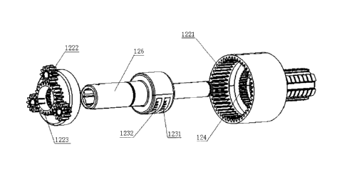
Figure 3 is an exploded view of the speed increasing bidirectional mechanical
converter
of the screwdriver shown in Figure 1. Figures 4 and 5 show the connectivity of
the speed
increasing bidirectional mechanical converter of the screwdriver shown in
Figure 1. As
shown in Figures 3-5, the speed increasing bidirectional mechanical converter
includes a
main shaft 126, a speed increasing planet unit and a reversing means.
The speed increasing planet gear unit includes a first ring gear 1221, a
planet gear 1222, a
sun gear 1223 and a planet carrier 1224, wherein the planet gear 1222 is
mounted on the
planet carrier 1224, the planet gear 1222 is arranged between the first ring
gear 1221 and
the sun gear 1223, and the first ring gear 1221 rotates in an opposite
direction against the
12
CA 02954786 2017-01-10
sun gear 1223, as shown in Figure 6.
As shown in Figure 3, the reversing means includes a first one-way clutch 1231
and a
second one-way clutch 1232 with same functioning directions which are same
with a
preset direction, i.e. the direction the main shaft 126 rotates.
The speed increasing bidirectional mechanical converter in the embodiment
utilizes the
technical feature that in the speed increasing planet gear unit the first ring
gear 1221 and
the sun gear 1223 rotate in opposite directions, and makes the first ring gear
1221 and the
sun gear 1223 to drive the main shaft 126 respectively via the first one-way
clutch 1231
and the second one-way clutch 1232 with same functioning directions, thereby
realizes
the reverse of the directions. The main shaft 126 rotates in the preset
direction no matter a
clockwise or anticlockwise torque is applied to the first ring gear 1221.
The speed increasing bidirectional mechanical converter further includes a
second ring
gear 124 which is coaxially arranged with the first ring gear 1221 and
connected to the
first one-way clutch 1231. This enables the first ring gear 1221 to drive the
main shaft
126 via the first one-way clutch 1231. In the embodiment, the first ring gear
1221 and the
second ring gear 124 are integrated.
It also works that the first ring gear 1221 and the second ring gear 124 are
non-integrated,
but coaxially connected.
The speed increasing bidirectional mechanical converter further includes a
third ring gear
125 which is coaxially arranged with the sun gear 1223 and connected to the
second
one-way clutch 1232. This enables the sun gear 1223 to drive the main shaft
126 via the
second one-way clutch 1232. In the embodiment, the sun gear 1223 and the third
ring
13
CA 02954786 2017-01-10
gear 125 are integrated.
It also works that the sun gear 1223 and the third ring gear 125 are non-
integrated, but
coaxially connected.
Figure 7 shows the connectivity between the main shaft 126 and each part.
The main shaft 126 is connected to the rod 11 via a pin, which enables the
main shaft 126
and the rod 11 to be arranged coaxially. When the main shaft 126 rotates, it
drives the rod
11 to rotate.
In the embodiment, the first one-way clutch 1231 and the second one-way clutch
1232
are pawls. While the first one-way clutch 1231 and the second one-way clutch
1232 can
be structured otherwise.
As shown in Figure 8, a blind hole is arranged in the switching shaft 121. A
spring is
arranged in the blind hole. A ball is arranged at the opening of the blind
hole. The pawl
1232 has a curved surface at the side facing the switching shaft 121, which
engages with
the ball, forming a connection between the pawl 1232 and the switching shaft
121,
enabling the rotation of the switching shaft 121 to drive the pawl 1232 to
rotate.
The pawl 1232 is mounted on the main shaft 126 via a pin 1261. There are teeth
on the
two opposite sides of the pawl 1232. At the position shown in Figure 7, the
teeth on one
side of the pawl 1232 engage with the third ring gear 125, and when the third
ring gear
125 rotates clockwise, the main shaft 126 is driven to rotate clockwise
because the sun
gear 1223 and the third ring gear 125 are integrated. That is to say, the sun
gear 1223
drives the main shaft 126 to rotate clockwise. When the third ring gear 125
rotates
14
CA 02954786 2017-01-10
anticlockwise, the pawl 1232 disengages with the third ring gear 125, thus
cannot drive
the main shaft 126 to rotate. The third ring gear 125 idles relative to the
main shaft 126.
That is to say, the sun gear 1223 idles relative to the main shaft 126.
As shown in Figure 9, a blind hole is arranged in the switching shaft 121. A
spring is
arranged in the blind hold. A ball is arranged at the opening of the blind
hole. The pawl
1231 has a curved surface at the side facing the switching shaft 121, which
engages with
the ball, forming a connection between the pawl 1231 and the switching shaft
121.The
pawl 1231 is mounted on the main shaft 126 via the pin 1261. There are teeth
on the two
opposite sides of the pawl 1231. At the position shown in Figure 8, the teeth
on one side
of the pawl 1231 engage with the second ring gear 124, and when the second
ring gear
124 rotates clockwise, the main shaft 126 is driven to rotate clockwise
because the first
ring gear 1221 and the second ring gear 124 are integrated. That is to say,
the first ring
gear 1221 drives the main shaft 126 to rotate clockwise. When the second ring
gear 124
rotates anticlockwise, the pawl 1231 disengages with the second ring gear 145,
thus
cannot drive the main shaft 126 to rotate. The second ring gear 124 idles
relative to the
main shaft 126. That is to say, the first ring gear 1221 idles relative to the
main shaft 126.
At the position shown in Figures 8 and 9, the functioning directions of the
pawls 1231
and 1232 are clockwise. That is to say, in the ring gears 124 and 125 which
engage with
the pawls 1231 and 1232, only the one rotates clockwise can drive the main
shaft 126 to
rotate clockwise. That is to say, the preset direction is same with the
functioning
directions of the pawls 1232 and 1232, which is clockwise.
Rotate the switching shaft 121 to change the teeth of the pawls 1231 and 1232
that
engage with the main shaft 126, the rotating direction of the main shaft 126
can be
reversed.
CA 02954786 2017-01-10
The handle 13, which is arranged coaxially with the first ring gear 1221, is
used for
inputting torque.
The holding ring 14 is used for keeping the planet carrier 1224 still.
In the embodiment, the holding ring 14 and the planet carrier 1224 are
integrated.
It also works that the holding ring 14 and the planet carrier 1224 are non-
integrated, but
fixedly connected.
When use the screwdriver of the embodiment, hold the holding ring 14 to keep
the planet
carrier 1224 still, rotate the handle 13 clockwise to apply a clockwise torque
to the first
ring gear 1221, enabling the second ring gear 125 to rotate clockwise. As
shown in Figure
9, the second ring gear 125 drives the main shaft 126 to rotate clockwise, the
first ring
gear 1221 drives the sun gear 1223 to rotate anticlockwise via the planet gear
1222,
enabling the third ring gear 124 to rotate anticlockwise. As shown in Figure
8, the third
ring gear 124 idles relative to the main shaft 126. That is to say, the sun
gear 1223 idles
relative to the main shaft 126.
In the screwdriver of the embodiment, the pawl 1231 and the first ring gear
1221
constitute a master ratchet, the pawl 1232 and the sun gear 1223 constitute an
assistant
ratchet. The planet gear 1222 is arranged between the sun gear 1223 and the
second ring
gear 125 which is integrated with the first ring gear. After reversing by the
holding ring
14, the assistant ratchet that is reverse to the master ratchet is formed.
When the master
ratchet rotates anticlockwise and drives the rod 11 to rotate anticlockwise,
the assistant
ratchet idles because of the reversing. When the master ratchet rotates
clockwise, the
16
CA 02954786 2017-01-10
master ratchet idles while the assistant ratchet drives the rod 11 to rotate
anticlockwise
after being reversed via the holding ring 14. Thus it is realized that the rod
11 rotates in
one direction no matter a clockwise or anticlockwise torque is applied to the
first ring
gear 1221 by rotating the handle 13, when the holding ring 14 is held to keep
the planet
carrier 1224 still.
The transmission ratio of the speed increasing planet gear unit is equal to
the gear ratio
between the first ring gear 1221 and the planet gear 1222. In the embodiment,
the
transmission ratio is 3. When the handle 13 rotates clockwise, the rod 11
which is
coaxially arranged with the main shaft 126 rotates clockwise at the same
speed. When the
handle 13 rotates anticlockwise, the rod 11 which is coaxially arranged with
the main
shaft 126 rotates clockwise at triple the speed.
The speed increasing bidirectional mechanical converter in the embodiment
further
includes a switching means, which is used for switching the functioning
directions of the
first one-way clutch 1231 and the second one-way clutchl 232.
As shown in Figure 10, the switching means includes a switching shaft 121, a
spiral
groove 1211 arranged on the switching shaft 121 and a push button 127 one end
of which
is arranged in the spiral groove 1211. As shown in Figure 7, the push button
127 is
arranged in a long hole of the main shaft 126. The button cover 15 is sheathed
outside the
main shaft 126. When the button cover 15 moves axially along the main shaft
126, it
drives the push button 127 to move axially in the long hole of the main shaft
126 along
the main shaft 126. The one end of the push button 127 moves along the spiral
groove
1211 to enable the switching shaft 121 to rotate, to drive the first one-way
clutch 1231
and the second one-way clutch 1232 to rotate relative to the pin 1261. Thus
the
functioning directions of the first one-way clutch 1231 and the second one-way
clutch
17
CA 02954786 2017-01-10
1232 are reversed.
As shown in Figure 11, two curved concaves are arranged on the inner side of
the main
shaft 126. A blind hole is arranged to the switching shaft 121. A spring is
arranged in the
blind hole. A ball is arranged at the opening of the blind hole. After the
rotation of the
switching shaft 121, the ball engages in the curved concaves, to keep the
functioning
directions of the first one-way clutch 1231 and the second one-way clutch 1232
stable
during the use of the screwdriver.
The screwdriver in the embodiment utilizes the technical feature that in the
speed
increasing planet gear unit the first ring gear 1221 and the sun gear 1223
rotates in
opposite directions, and makes the first ring gear 1221 and the sun gear 1223
to drive the
main shaft 126 respectively via the first one-way clutch 1231 and the second
one-way
clutch 1232 with same functioning directions, to realize the reverse of the
directions. The
rod 11 rotates in a preset direction no matter the handle 13 rotates clockwise
or
anticlockwise. When the handle 13 rotates in the same direction as the preset
direction,
the rod 11 and the handle 13 rotate in the preset direction at a same speed.
When the
handle 13 rotates in the opposite direction to the preset direction, the rod
11 rotates in the
preset direction at triple the speed of the handle 13. The switching means is
for reversing
the preset direction.
Figure 12 is a front view of a wrench including a speed increasing
bidirectional
mechanical converter in another embodiment of the present invention. Figure 13
is a part
sectional view of the wrench shown in Figure 12. As shown in Figures 12 and
13, the
wrench including the speed increasing bidirectional mechanical converter in
the
embodiment includes: a switching knob 227, a holding means, a speed increasing
bidirectional mechanical converter, a handle 23 and a torque outputting part
21, wherein
18
CA 02954786 2017-01-10
the holding means is a holding ring 24 which is a conical ring.
As shown in Figure 14, the speed increasing bidirectional mechanical converter
includes
a main shaft 226, a speed increasing planet gear unit and a reversing means,
wherein the
main shaft 226 and the torque outputting part 21 are arranged coaxially.
The speed increasing planet gear unit includes a first ring gear 2221, a
planet gear 1222, a
sun gear 2223 and a planet carrier 2224, wherein the planet gear 2222 is
mounted on the
planet carrier 2224, the planet gear 2222 is arranged between the first ring
gear 2221 and
the sun gear 2223, and the first ring gear 2221 rotates in an opposite
direction against the
sun gear 2223.
The reversing means includes a first one-way clutch 2231 and a second one-way
clutch
2232 with same functioning directions. The functioning directions are same
with a preset
direction, i.e. the direction the main shaft 226 rotates in.
The speed increasing bidirectional mechanical converter in the embodiment
utilizes the
technical feature that in the speed increasing planet gear unit the first ring
gear 2221 and
the sun gear 2223 rotate in opposite directions, and makes the first ring gear
2221 and the
sun gear 2223 to drive the main shaft 226 respectively via the first one-way
clutch 2231
and the second one-way clutch 2232 with same functioning directions, to
realize the
reverse of the directions. The main shaft 226 rotates in the preset direction
no matter a
clockwise or anticlockwise torque is applied to the first ring gear 2221.
The speed increasing bidirectional mechanical converter further includes a
second ring
gear 224 which is coaxially arranged with the first ring gear 2221 and
connected to the
first one-way clutch 2231. This enables the first ring gear 2221 to drive the
main shaft
19
CA 02954786 2017-01-10
226 via the first one-way clutch 2231. In the embodiment, the first ring gear
2221 and the
second ring gear 224 are non-integrated and connected coaxially.
The speed increasing bidirectional mechanical converter further includes a
third ring gear
225 which is coaxially arranged with the sun gear 2223 and connected to the
second
one-way clutch 2232. This enables the sun gear 2223 to drive the main shaft
226 via the
second one-way clutch 2232. In the embodiment, the sun gear 1223 and the third
ring
gear 125 are integrated.
The main shaft 226 is fixedly connected to the torque outputting part 21. When
the main
shaft 226 rotates, it drives the torque outputting part 21 to rotate.
In the embodiment, the first one-way clutch 2231 and the second one-way clutch
2232
are pawls.
As shown in Figure 15, the first one-way clutch 2231 includes a pair of pawls.
Curved
surface is arranged on the pawl's side facing the switching shaft 221. A
through hole is
arranged in the switching shaft 221. A spring is arranged in the through hole.
Two ball
plungers are arranged at the two openings of the through hole respectively and
engaged to
the curved surface on the pawls, forming the connection between the first one-
way clutch
2231 and the switching shaft 221.
The first one-way clutch 2231 is mounted on the main shaft 226 via a pin.
There are teeth
on the two opposite sides of the first one-way clutch 2231. At the position
shown in
Figure 15, the teeth on one side of the first one-way clutch 2231 engage with
the second
ring gear 224, and when the second ring gear 224 rotates clockwise, the main
shaft 226 is
driven to rotate clockwise because the first ring gear 2221 and the second
ring gear 224
CA 02954786 2017-01-10
are connected coaxially. That is to say, the first ring gear 2221 drives the
main shaft 226
to rotate clockwise. When the second ring gear 224 rotates anticlockwise, the
first
one-way clutch 2231 disengages with second ring gear 224, thus cannot drive
the main
shaft 226 to rotate. The second ring gear 224 idles relative to the main shaft
226. That is
to say, the first ring gear 2221 idles relative to the main shaft 226.
As shown in Figure 16, the second one-way clutch 2232 includes a pair of
pawls. Curved
surface is arranged on the pawl's side facing the switching shaft 221. A
through hole is
arranged in the switching shaft 221. A spring is arranged in the through hole.
Two ball
plungers are arranged at the two openings of the through hole respectively and
engaged to
the curved surface on the pawls, forming the connection between the second one-
way
clutch 2232 and the switching shaft 221.
The second one-way clutch 2232 is mounted on the main shaft 226 via a pin.
There are
teeth on the two opposite sides of the second one-way clutch 2232. At the
position shown
in Figure 16, the teeth on one side of the second one-way clutch 2232 engage
with the
third ring gear 225, and when the third ring gear 225 rotates clockwise, the
main shaft
226 is driven to rotate clockwise because the sun gear 2223 and the third ring
gear 225
are integrated. That is to say, the sun gear 2223 drives the main shaft 226 to
rotate
clockwise. When the third ring gear 225 rotates anticlockwise, the second one-
way clutch
2232 disengages with third ring gear 225, thus cannot drive the main shaft 226
to rotate.
The third ring gear 225 idles relative to the main shaft 226. That is to say,
the sun gear
2223 idles relative to the main shaft 226.
At the position shown in Figures 15 and 16, the functioning directions of the
one-way
clutches 2231 and 2232 are clockwise. That is to say, in the ring gears 224
and 225 which
engage with the one-way clutches 2231 and 2232, only the one rotates clockwise
can
21
CA 02954786 2017-01-10
drive the main shaft 226 to rotate clockwise. That is to say, the preset
direction is same
with the functioning directions of the one-way clutches 2232 and 2232, which
is
clockwise.
The handle 13 is used for inputting torque.
As shown in Figure 17, the second ring gear 224 is arranged in the handle 23
and they are
integrated. Three curved concave parts are arranged along the circular inner
side of the
second ring gear 224 which is facing the first ring gear 2221. As shown in
Figure 14, the
three curved concave parts are engaged with the three convex parts on the side
of the first
ring gear 2221 which is facing the second ring gear 224, forming the coaxial
connection
between the second ring gear 224 and the first ring gear 2221.
Other coaxial connection between the second ring gear 224 and the first ring
gear 2221
can be adopted, which is not limited by the present invention.
The holding ring 24 is used for keeping the planet carrier 2224 still.
In the embodiment, the holding ring 24 and the planet carrier 2224 are non-
integrated and
fixedly connected.
When use the wrench of the embodiment, hold the holding ring 24 to keep the
planet
carrier 2224 still, rotate the handle 23 clockwise to apply a clockwise torque
to the
second ring gear 225, enabling the first ring gear 2221 rotates clockwise. As
shown in
Figure 16, the second ring gear 225 drives the main shaft 226 to rotate
clockwise, the first
ring gear 2221 drives the sun gear 2223 to rotate anticlockwise via the planet
gear 2222,
enabling the third ring gear 224 to rotate anticlockwise. As shown in Figure
15, the third
22
CA 02954786 2017-01-10
ring gear 224 idles relative to the main shaft 226. That is to say, the sun
gear 2223 idles
relative to the main shaft 126.
When use the wrench of the embodiment, hold the holding ring 24 to keep the
planet
carrier 2224 still, rotate the handle 23 anticlockwise to apply an
anticlockwise torque to
the second ring gear 225, enabling the first ring gear 2221 rotates
anticlockwise. As
shown in Figure 16, the second ring gear 225 idles relative to the main shaft
126, the first
ring gear 2221 drives the sun gear 2223 to rotate clockwise at an increased
speed via the
planet gear 2222, enabling the third ring gear 224 to rotate clockwise. As
shown in Figure
15, the third ring gear 224 drives the main shaft 226 to rotate clockwise.
That is to say,
the sun gear 2223 drives the main shaft 126 to rotate clockwise.
The transmission ratio of the speed increasing planet gear unit is equal to
the gear ratio
between the first ring gear 2221 and the planet gear 2222. In the embodiment,
the
transmission ratio is 3. When the handle 23 rotates clockwise, the torque
outputting part
21 which is coaxially arranged with the main shaft 226 rotates clockwise at
the same
speed. When the handle 23 rotates anticlockwise, the torque outputting part 21
which is
coaxially arranged with the main shaft 226 rotates clockwise at triple the
speed.
The speed increasing bidirectional mechanical converter in the embodiment
further
includes a switching means, which is used for switching the functioning
directions of the
first one-way clutch 2231 and the second one-way clutch 2232.
The switching means includes a switching shaft 221 and a switching knob 227
arranged
on the switching shaft 221. Rotate the switching knob 227, the switching shaft
221 is
driven to rotate, driving the first one-way clutch 2231 and the second one-way
clutch
2232 to rotate relative to the pin. Thus the functioning directions of the
first one-way
23
CA 02954786 2017-01-10
clutch 2231 and the second one-way clutch 2232 are reversed.
The wrench in the embodiment further includes an unlocking means, which
includes a
ball arranged on the torque outputting part 21, the switching knob 227, a
spring 26, and a
first groove 2212 and a second groove 2213 which are arranged in the switching
shaft
221. As shown in Figure 18, the first groove 2212 and the second groove 2213
have
different depths. The ends of the first groove 2212 and the second groove 2213
which are
closer to the switching knob 227 have deeper depths.
When the switching knob 227 is pushed down, the ball enters the deeper part of
the first
groove 2212 or the second groove 2213 and the unlocking is achieved. When the
switching knob 227 is released, the elastic force provided by the sheathed
spring 26
restores the switching knob 227 to its original position and enable the ball
to move to the
shallower part and bounce up.
The wrench in the embodiment utilizes the technical feature that in the speed
increasing
planet gear unit the first ring gear 2221 and the sun gear 2223 rotates in
opposite
directions, and makes the first ring gear 2221 and the sun gear 2223 to drive
the main
shaft 226 respectively via the one-way clutches 1231 and 1232 with same
functioning
directions, to realize the reverse of the directions. The torque outputting
part 21 rotates in
the preset direction no matter the handle 23 rotates clockwise or
anticlockwise. When the
handle 23 rotates in the same direction as the preset direction, the torque
outputting part
21 and the handle 23 rotate in the preset direction at a same speed. When the
handle 23
rotates in the opposite direction to the preset direction, the torque
outputting part 21
rotates in the preset direction at triple the speed of the handle 23. The
switching means is
for reversing the preset direction.
24
CA 02954786 2017-01-10
,
What illustrated above are preferred embodiments of the present invention. It
should be
understood that persons skilled in the art can make many modifications and
changed in
accordance with the concept of the invention without creative work. So any
technical
solutions obtained through logical analyzing, reasoning or limited experiments
in
accordance with the concept of the present invention by the persons skilled in
the art shall
fall within the scope of the claims.